Tài liệu Lab 6.2.6 Add, Move, and Change MAC Addresses docx
Bạn đang xem bản rút gọn của tài liệu. Xem và tải ngay bản đầy đủ của tài liệu tại đây (256.65 KB, 7 trang )
Lab 6.2.6 Add, Move, and Change MAC Addresses
Objective
• Create and verify a basic switch configuration.
• Move a PC from one switch port to another and add a new PC to the switch.
Background / Preparation
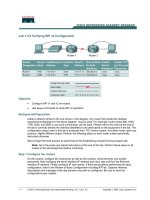
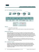
Cable a network similar to the one in the diagram. The configuration output used in this lab is
produced from a 2950 series switch. Any other switch used may produce different output. The
following steps are to be executed on each switch unless specifically instructed otherwise.
Start a HyperTerminal session.
Note: Go to the erase and reload instructions at the end of this lab. Perform those steps on all
switches in this lab assignment before continuing.
Step 1 Configure the switch
Configure the hostname, access and command mode passwords, as well as the management VLAN
settings. These values are shown in the chart. If problems occur while performing this configuration,
refer to the Basic Switch Configuration lab.
1 - 7 CCNA 3: Switching Basics and Intermediate Routing v 3.0 - Lab 6.2.6 Copyright 2003, Cisco Systems, Inc.
Step 2 Configure the hosts attached to the switch
Configure the hosts to use the same IP subnet for the address, mask, and default gateway as on the
switch.
There is a third host needed for this lab. It needs to be configured with the address 192.168.1.7. The
subnet mask is 255.255.255.0 and the default gateway is 192.168.1.1. Do not connect this PC to the
switch yet.
Step 3 Verify connectivity
a. To verify that the hosts and switch are correctly configured, ping the switch IP address from the
hosts.
b. Were the pings successful? __________________________________________________
c. If the answer is no, troubleshoot the hosts and switch configurations.
Step 4 Record the MAC addresses on the hosts
a. To determine and record the layer 2 addresses of the PC network interface cards enter the
following.
If running Windows 98, check by using Start > Run > winipcfg. Click on More info.
If running Windows 2000, check by using Start > Run > cmd > ipconfig /all.
b. PC1:
___________________________________________________________________
c. PC4:
___________________________________________________________________
Step 5 Determine what MAC addresses the switch has learned
a. Determine what MAC addresses the switch has learned by using the show mac-address-
table command, as shown, at the privileged exec mode prompt.
ALSwitch#show mac-address-table
b. How many dynamic addresses are there?
________________________________________
c. How many total MAC addresses are there?
_______________________________________
d. Do the MAC addresses match the host MAC addresses?
_____________________________
Step 6 Determine the show MAC table options
To determine the options that the mac-address-table command has using enter the ? option as
follows:
ALSwitch(config)#mac-address-table ?
Step 7 Set up a static MAC address
To setup a static MAC address on Fast Ethernet interface 0/4 enter the following:
Note: Use the address that was recorded for PC4 in step 4. The MAC address 00e0.2917.1884 is
used in the example statement only.
ALSwitch(config)#mac-address-table static 00e0.2917.1884 interface
fastethernet 0/4 vlan 1
2900:
ALSwitch(config)#mac-address-table static 00e0.2917.1884
fastethernet 0/4 vlan 1
2 - 7 CCNA 3: Switching Basics and Intermediate Routing v 3.0 - Lab 6.2.6 Copyright 2003, Cisco Systems, Inc.
1900:
ALSwitch(config)#mac-address-table permanent 00e0.2917.1884 ethernet
0/4
Step 8 Verify the results
a. To verify the mac address table entries.
ALSwitch#show mac-address-table
b. How many static addresses are there?
__________________________________________
Step 9 List port security options
a. To determine the options for setting port security on interface Fast Ethernet 0/4. Type port
security ? from the interface configuration prompt for Fast Ethernet port 0/4.
ALSwitch(config)#interface fastethernet 0/4
ALSwitch(config-if)#switchport port-security ?
aging Port-security aging commands
mac-address Secure mac address
maximum Max secure addrs
violation Security Violation Mode
<cr>
1900:
ALSwitch(config)#interface ethernet 0/4
ALSwitch(config-if)#port secure ?
max-mac-count Maximum number of addresses allowed on the port
<cr>
b. Allow the switchport on Fast Ethernet 0/4 to accept only one device by typing port-security as
follows:
ALSwitch(config-if)#switchport mode access
ALSwitch(config-if)#switchport port-security
ALSwitch(config-if)# switchport port-security mac-address sticky
1900:
ALSwitch(config-if)#port secure
Step 10 Verify the results
a. Enter the following to verify the mac–address-table entries:
ALSwitch#show mac-address-table
b. How are the address types listed for the two MAC addresses?
________________________
Step 11 Show the running configuration file
3 - 7 CCNA 3: Switching Basics and Intermediate Routing v 3.0 - Lab 6.2.6 Copyright 2003, Cisco Systems, Inc.
a. In the listing of the running configuration are there statements that directly reflect the security
implementation?
__________________________________________________________
b. What do those statements mean?
______________________________________________
__________________________________________________________________________
Step 12 Limit the number of hosts on each port
a. Enter the following on interface Fast Ethernet 0/4 to set the port security maximum MAC count to
1:
ALSwitch(config)#interface fastethernet 0/4
ALSwitch(config-if)#switchport port-security maximum 1
1900:
ALSwitch(config)#interface ethernet 0/4
ALSwitch(config-if)#port secure max-mac-count 1
b. Disconnect the PC that is attached to Fast Ethernet 0/4. Connect to the port that the PC has
been given the IP address 192.168.1.7. This PC has not yet been attached to the switch. To
generate some traffic ping the switch address 192.168.1.2 with the -n 50 option. For example
ping 192.168.1.2 –n 50, where 50 is the number of pings sent.
Step 13 Move host
a. Take the PC that had previously been connected to Fast Ethernet 0/4 and reconnect it to Fast
Ethernet 0/8. The PC has been moved to a new location. This could be to another VLAN but in
this instance all switch ports are in VLAN 1 and network 192.168.1.0.
b. From this PC on Fast Ethernet 0/8, ping 192.168.1.2 –n 50
c. Was the ping successful?
___________________________________________________
d. Why or why not?
__________________________________________________________
e. Enter the following to show the mac-address-table.
ALSwitch#show mac-address-table
f. Record observations about the show output. ______________________________________
__________________________________________________________________________
Step 14 Clear MAC table
a. Enter the following to clear the mac-address-table:
Note: This will unlock the MAC addresses from security and allow a new address to be
registered.
ALSwitch#clear mac-address-table dynamic
b. From the PC on the Fast Ethernet 0/8, ping 192.168.1.2 –n 50
c. Was the ping successful?
___________________________________________________
d. If not troubleshoot as necessary.
Step 15 Change security settings
a. Enter the following to show the mac-address-table:
4 - 7 CCNA 3: Switching Basics and Intermediate Routing v 3.0 - Lab 6.2.6 Copyright 2003, Cisco Systems, Inc.
ALSwitch#show mac-address-table
b. Notice that Fast Ethernet 0/4 is secure. However, that security should be applied to the machine
on port 0/8, as this is the machine that was moved from port 0/4. Remove port security from
interface Fast Ethernet 0/4 as follows:
ALSwitch(config)#interface fastethernet 0/4
ALSwitch(config-if)# no switchport port-security
ALSwitch(config-if)# no switchport port-security mac-address sticky
ALSwitch(config-if)# no switchport port-security mac-address sticky
0008.744d.8ee2
ALSwitch(config-if)#shutdown
ALSwitch(config-if)#no shutdown
1900:
ALSwitch(config)#interface ethernet 0/4
ALSwitch(config-if)#no port secure
c. Apply port security with a max-mac-count of 1 to interface Fast Ethernet 0/8 as follows:
ALSwitch(config)#interface fastethernet 0/8
ALSwitch(config-if)#switchport mode access
ALSwitch(config-if)# switchport port-security
ALSwitch(config-if)# switchport port-security mac-address sticky
ALSwitch(config-if)#switchport port-security maximum 1
1900:
ALSwitch(config)#interface ethernet 0/8
ALSwitch(config-if)#port secure max-mac-count 1
d. Enter the following to clear the mac-address-table.
Note: Clearing individual entries could have also been done.
ALSwitch#clear mac-address-table
Step 16 Verify the results
a. Verify that the mac-address-table has been cleared.
ALSwitch#show mac-address-table
b. Can all PCs still successfully ping each other? ______________
c. If not troubleshoot the switch and PCs.
Step 17 Exit the switch
Type exit to leave the switch welcome screen as follows:
Switch#exit
5 - 7 CCNA 3: Switching Basics and Intermediate Routing v 3.0 - Lab 6.2.6 Copyright 2003, Cisco Systems, Inc.
Once the steps are complete, logoff, by typing exit, and turn all the devices off. Then remove and
store the cables and adapter.
6 - 7 CCNA 3: Switching Basics and Intermediate Routing v 3.0 - Lab 6.2.6 Copyright 2003, Cisco Systems, Inc.
Erasing and reloading the Switch
Enter into the privileged exec mode by typing enable.
If prompted for a password, enter class (if that does not work, ask the instructor).
Switch>enable
Switch#delete flash:vlan.dat
Delete filename [vlan.dat]?[enter]
Delete flash:vlan.dat? [confirm] [enter]
If there was no VLAN file, this message is displayed.
%Error deleting flash:vlan.dat (No such file or directory)
At the privileged exec mode enter the command erase startup-config.
Switch#erase startup-config
The responding line prompt will be:
Erasing the nvram filesystem will remove all files! Continue? [confirm]
Press Enter to confirm.
The response should be:
Erase of nvram: complete
Now at the privileged exec mode enter the command reload.
Switch(config)#reload
The responding line prompt will be:
System configuration has been modified. Save? [yes/no]:
Type n and then Enter.
The responding line prompt will be:
Proceed with reload? [confirm] [Enter]
In the first line of the response will be:
Reload requested by console.
After the Switch has reloaded the line prompt will be:
Would you like to enter the initial configuration dialog? [yes/no]:
Type n and then Enter.
The responding line prompt will be:
Press RETURN to get started! [Enter]
7 - 7 CCNA 3: Switching Basics and Intermediate Routing v 3.0 - Lab 6.2.6 Copyright 2003, Cisco Systems, Inc.