Tài liệu Lab 6.2.9 Firmware Upgrade of a Catalyst 2900 Series Switch doc
Bạn đang xem bản rút gọn của tài liệu. Xem và tải ngay bản đầy đủ của tài liệu tại đây (138.15 KB, 5 trang )
1 - 5 CCNA 3: Switching Basics and Intermediate Routing v 3.0 - Lab 6.2.9 Copyright 2003, Cisco Systems, Inc.
Lab 6.2.9 Firmware Upgrade of a Catalyst 2900 Series Switch
Objective
• Create a basic switch configuration verify it.
• Upgrade the IOS and HTML files from a file supplied by the instructor.
Background/Preparation
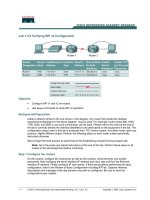
Cable a network similar to the one in the diagram. The configuration output used in this lab is
produced from a 2950 series switch. Any other switch used may produce different output. The
following steps are to be executed on each switch unless specifically instructed otherwise.
Start a HyperTerminal session.
Notes: This lab requires that a combination of an IOS image and the HTML file c2950-c3h2s-
mz.120-5.3.WC.1.tar be used as the default file directory of the TFTP server. This file should be
downloaded, by the instructor, from the Cisco Connection on-line software center. It has been
determined that this file is the latest update for the Catalyst 2950. This has the same file name
stem as the current image. However, for the purpose of the lab, assume that this is an update.
The IOS update release contains new HTML files to support changes to the web interface.
This lab requires that there is a saved a copy of the current configuration file as backup.
Note: Go to the erase and reload instructions at the end of this lab. Perform those steps on all
switches in this lab assignment before continuing.
Step 1 Configure the switch
Configure the hostname, access, and command mode passwords, as well as the management LAN
settings. These values are shown in the chart. If problems occur while performing this configuration,
refer to the Basic Switch Configuration lab.
2 - 5 CCNA 3: Switching Basics and Intermediate Routing v 3.0 - Lab 6.2.9 Copyright 2003, Cisco Systems, Inc.
Step 2 Configure the host attached to the switch
Configure the host to use the same IP subnet for the address, mask, and default gateway as on the
switch.
Step 3 Verify connectivity
a. To verify that the host and switch are correctly configured, ping the switch IP address from the
host.
b. Was the ping successful?
____________________________________________________
c. If the answer is no, troubleshoot the host and switch configurations.
Step 4 Display the name of the running image file
a. Display the name of the running image file using the show boot command from the privileged
EXEC mode prompt as follows:
ALSwitch#show boot
BOOT path-list:
Config file: flash:config.text
Enable Break: no
Manual Boot: no
HELPER path-list:
NVRAM/Config file
buffer size: 32768
ALSwitch#
b. If there is no software image defined in the boot path, enter dir flash: or show flash to
display the contents as follows:
ALSwitch#dir flash:
Directory of flash:/
2 -rwx 1674921 Mar 01 1993 01:28:10 c2950-c3h2s-mz.120-5.3.WC.1.bin
3 -rwx 269 Jan 01 1970 00:00:57 env_vars
4 drwx 10240 Mar 01 1993 00:21:13 html
165-rwx 965 Mar 01 1993 00:22:23 config.text
7741440 bytes total (4778496 bytes free)
Step 5 Prepare for the new image
a. If the switch has enough free memory as shown in the last command, rename the existing IOS
file to the same name with the .old extension as follows:
Note: If there is not enough memory, make sure there is a copy of the IOS on the TFTP server.
ALSwitch#rename flash: c2950-c3h2s-mz.120-5.3.WC.1.bin flash: c2950-
c3h2s-mz.120-5.3.WC.1.old
b. Enter the following to verify that the renaming was successful:
ALSwitch#dir flash:
Directory of flash:/
2 -rwx 1674921 Mar 01 1993 01:28:10 c2950-c3h2s-mz.120-5.3.WC.1.old
3 - 5 CCNA 3: Switching Basics and Intermediate Routing v 3.0 - Lab 6.2.9 Copyright 2003, Cisco Systems, Inc.
3 -rwx 269 Jan 01 1970 00:00:57 env_vars
4 drwx 10240 Mar 01 1993 00:21:13 html
167 -rwx 965 Mar 01 1993 00:22:23 config.text
7741440 bytes total (4778496 bytes free)
ALSwitch#
c. As a precaution, enter the following to disable access to the switch HTML pages:
ALSwitch(config)#no ip http server
d. Remove existing html files.
ALSwitch#delete flash:html/*
Step 6 Extract the new IOS image and HTML files into flash memory
a. Enter the following to extract the new IOS image and HTML files into flash memory:
ALSwitch#archive tar /x tftp://192.168.1.3/c2950-c3h2s-mz.120-
5.3.WC.1.tar flash:
Note: Depending on the TFTP server being used only one slash (/) after the IP address of the
server may be needed.
b. Re-enable access to the switch HTML pages as follows:
ALSwitch(config)#ip http server
c. Remove existing html files.
ALSwitch#delete flash:html/*
Step 7 Associate the new boot file
Enter the boot command with the name of the new image filename at the configuration mode
prompt.
ALSwitch(config)#boot system flash:c2950-c3h2s-mz.120-5.4.WC.1.bin
Step 8 Restart the switch
a. Restart the switch by using the reload command to see if the new IOS loaded. Use the show
version command to see the IOS file name.
b. What was the name of the IOS file the switch booted from?
___________________________
c. Was this the proper file name?
________________________________________________
d. If the IOS filename is now correct remove the backup file from flash memory using the command
delete flash: c2950-c3h2s-mz.120-5.3.WC.1.old from the privileged EXEC mode
prompt to remove the backup file.
Once the steps are completed, logoff by typing exit, and turn all the devices off. Then remove and
store the cables and adapter.
4 - 5 CCNA 3: Switching Basics and Intermediate Routing v 3.0 - Lab 6.2.9 Copyright 2003, Cisco Systems, Inc.
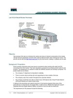
Erasing and Reloading the Switch
For the majority of the labs in CCNA 3 and CCNA 4 it is necessary to start with an unconfigured
switch. Use of a switch with an existing configuration may produce unpredictable results. These
instructions allow preparation of the switch prior to performing the lab so previous configuration
options do not interfere. The following is the procedure for clearing out previous configurations and
starting with an unconfigured switch. Instructions are provided for the 2900, 2950, and 1900 Series
switches.
2900 and 2950 Series Switches
1. Enter into the privileged EXEC mode by typing enable.
If prompted for a password, enter class (if that does not work, ask the instructor).
Switch>enable
2. Remove the VLAN database information file.
Switch#delete flash:vlan.dat
Delete filename [vlan.dat]?[Enter]
Delete flash:vlan.dat? [confirm] [Enter]
If there was no VLAN file, this message is displayed.
%Error deleting flash:vlan.dat (No such file or directory)
3. Remove the switch startup configuration file from NVRAM.
Switch#erase startup-config
The responding line prompt will be:
Erasing the nvram filesystem will remove all files! Continue? [confirm]
Press Enter to confirm.
The response should be:
Erase of nvram: complete
4. Check that VLAN information was deleted.
Verify that the VLAN configuration was deleted in Step 2 using the show vlan command. If
previous VLAN configuration information (other than the default management VLAN 1) is still
present it will be necessary to power cycle the switch (hardware restart) instead of issuing the
reload command. To power cycle the switch, remove the power cord from the back of the
switch or unplug it. Then plug it back in.
If the VLAN information was successfully deleted in Step 2, go to Step 5 and restart the switch
using the reload command.
5. Software restart (using the reload command)
5 - 5 CCNA 3: Switching Basics and Intermediate Routing v 3.0 - Lab 6.2.9 Copyright 2003, Cisco Systems, Inc.
Note: This step is not necessary if the switch was restarted using the power cycle method.
a. At the privileged EXEC mode enter the command reload.
Switch(config)#reload
The responding line prompt will be:
System configuration has been modified. Save? [yes/no]:
b. Type n and then press Enter.
The responding line prompt will be:
Proceed with reload? [confirm] [Enter]
The first line of the response will be:
Reload requested by console.
After the switch has reloaded, the line prompt will be:
Would you like to enter the initial configuration dialog? [yes/no]:
c. Type n and then press Enter.
The responding line prompt will be:
Press RETURN to get started! [Enter]
1900 Series Switches
1. Remove VLAN Trunking Protocol (VTP) information.
#delete vtp
This command resets the switch with VTP parameters set to factory
defaults.
All other parameters will be unchanged.
Reset system with VTP parameters set to factory defaults, [Y]es or
[N]o?
Enter y and press Enter.
2. Remove the switch startup configuration from NVRAM.
#delete nvram
This command resets the switch with factory defaults. All system parameters will revert to their
default factory settings. All static and dynamic addresses will be removed.
Reset system with factory defaults, [Y]es or [N]o?
Enter y and press Enter.