Tài liệu WSU CCIE Lab #3 Advanced Multiprotocol Skills Lab doc
Bạn đang xem bản rút gọn của tài liệu. Xem và tải ngay bản đầy đủ của tài liệu tại đây (89.65 KB, 8 trang )
1
Wichita State University
Department of Electrical and Computer Engineering
CCIE Preparation Laboratory
WSU CCIE Lab #3
Advanced Multiprotocol Skills Lab
Version 0.99.5-324, 11-8-2000
• Configure the network using network 140.10.x.x
• Use an 8 bit subnet mask unless otherwise specified
• If a password is needed, use cisco for the password
• X is router number, Y is rack number
• Do not use any type of static routes
• At the end of each exercise, verify connectivity between all devices
• Use the Catalyst 3920, SW3, for all of the rings, do not use the MAUs.
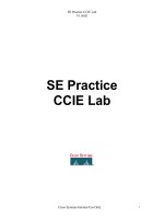
R5
R7
Frame
R6
ATM
ISDN
VLAN B
VLAN A
R1
Ring 1
Ring 3
Backbone
R4
R2
Backbone
R3
VLAN D
Ring 4
Ring 2
VLAN C
SW1
2
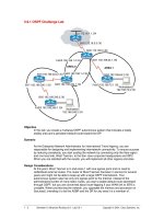
Frame Relay Setup
TERMINAL SERVER
Setup R5 as the terminal server, so that all routers can be accessed via reverse telnet. R5’s asynchronous serial
lines are connected as follows:
R1 – line 2001
R2 – line 2002
R3 – line 2003
R4 – line 2004
SW1 – line 2005
R6 – line 2006
R7 – line 2007
SW3 – line 2017
dlci 110
R6
R3
R2
R4
S3/0
S3/1
S3/2
S3/3
R8
dlci 110
dlci 110
dlci 100
dlci 140
dlci 104
3
4
NETWORK DIAGRAM
Make a network diagram that includes all addresses, frame relay DLCI’s and other pertinent information.
IP ADDRESSING
Use the class B network address 140.10.0.0 throughout the network, except on the backbone interfaces. Use the
subnet masks shown on page 1 and listed in the text. If a subnet mask is not given for an interface, use /24. For
Backbone 1 use the address 180.100.1.1 /24. For Backbone 2 use the address 180.200.1.1 /24.
LOOPBACKS
Configure a loopback on each router with the IP address of 140.10.X.X.
REMOTE ACCESS
All routers must be accessible by VTY session including enable mode.
FRAME RELAY
R8 is configured as the frame-relay switch. Configure frame relay between R2, R3, R4 and R6. Refer to diagram on
page 2 for the DLCI routing setup on the frame switch.
• The PVC between R2 and R6 should be on its own subnet.
• Use 1 PVC between R3 and R6, and one PVC between R4 and R6.
• The PVC’s between R3, R4 and R6 should be on a single subnet.
VLANS
Configure 4 VLANs on SW1.
• Set the switch’s VTP domain to WSU.
• R7 and R4’s ethernet interfaces are in VLAN 70.
• Ensure that if another switch were added to VLAN 70 your switch would be the root switch.
• Given 140.10.30.30/22 for the SC0 interface of SW1, configure the switch so that you can ping any device on
VLAN 70’s subnet from the switch.
• Configure port 1/1 as a trunking port with R6 for VLAN A, VLAN B, and VLAN C.
• Set the forwarding delay on VLAN 50, i.e. VLAN B, to 10 seconds.
• Use a /26 netmask for VLAN B.
• Create VLAN C (VLAN 30).
• Place R6 E0/0 in VLAN 60 on port 2/6.
• On VLAN A hosts have been configured to automatically get a default gateway. Make R6 the preferred way
and R4 the least preferred.
ATM
Configure R6’s ATM interface. Create sub-interface 0.6 with the IP address 180.6.Y.6 /24, where Y is the rack #.
Use PVC 30Y, where Y is the rack #. R6 should contact the switch for its addressing needs, but no more the every
5 minutes. Set QoS parameters for this PVC: UBR maximum is 10000 and minimum is 1000.
5
DHCP
Configure R4 as a DHCP server for clients on VLAN A and VLAN C. Use separate address pools for each VLAN.
On VLAN A use a single exclusion range to reserve 10 static IP addresses for network devices, including server,
routers, etc. Do not forward BOOTREQUEST messages form VLAN C to VLAN A. Assume there is a DNS and
WINS server 140.10.30.31/22 for all clients to use.
RIP
Configure R2 to receive IP RIP routes from Backbone 1. Only advertise the 140.10.0.0 network out to Backbone1.
There are 3 networks being advertised for Backbone1; 199.172.1.0, 199.172.3.0, and 199.172.12.0.
Combine these routes into 2 routes and redistribute into OSPF.
OSPF
Configure OSPF for the frame relay links between R2, R3, R4, and R6, for VLAN 70 and for Rings 2 and 3.
• The frame relay network should be in area 1.
• VLAN 70 should be in area 0.
• Rings 2 and 3 should be in area 7, which is to be configured as a stub area.
• Configure MD5 authentication in area 1.
• Place VLAN D in area 6.
• Change the cost of all ethernet interfaces in VLAN D to 90 without using the cost command.
• Place the loopbacks of each router in any of the above areas on the router. Do not create any new areas.
IGRP
Configure IGRP on R1 and the serial link between R1 and R5.
EIGRP
Configure EIGRP on R6. Use the rack number for the AS number.
IS-IS
Configure IS-IS between R5 and R6.
BACKUP LINK
Configure the serial link between R3 and R4 as a backup link for the FR cloud using PPP encapsulation. Use 1 of
the following routing protocols; EIGRP, IGRP, or RIP v1. Do not use ant backup interface commands, DDR, or
ODR. Data traffic should only pass over this link if the FR connectivity for R3 or R4 is lost.
REDISTRIBUTION
Redistribute so that all routes, except Backbone 1, are visible on all routers. Do not redistribute directly between
EIGRP and IS-IS. Advertise a default route form R6 to R5 and then from R5 to R1. Redistribute form EIGRP into
OSPF but not vise-versa. Full connectivity must be maintained including across the ATM cloud.
6
ISDN
Configure the ISDN link between R2 and R3 as a backup for the frame relay network. Do not use floating static
routes, or the ‘backup interface’ command. R3 should never call R2. R2 should call R3 with authentication but
not be challenged by R3. R3 must then call R2 back with the userid userY, where Y is the rack number.
• Should the frame network connected to R2 go down all routes should still be visible on both R2 and R3.
• The link should come up for any network topology changes.
• Broadcast traffic should not bring the link up.
• Use CHAP authentication.
BGP
Configure BGP on R1.
• R1should be in AS 100.
• Add a loopback 192.81.y.y/32 on R1. Advertise this network into BGP.
Configure BGP on R5.
• R5 should be in AS 500.
• Add a loopback 192.85.y.y/32 on R5. Advertise this network into BGP.
• On R5 put a filter, without using any address statement, to not redistribute R3’s loopback 1 (192.83.y.y) to R1.
Configure BGP on R7.
• R7 should be in AS 700.
• R7 should receive BGP updates from both R4 and R6. The BGP routing table on R7 should show R6 as the
only path for AS100 and AS 500. The BGP routing table on R7 should show R6 as the preferred path for
AS 1000. Traffic destined for all other autonomous systems should be balanced between both R4 and R6.
Configure BGP on R3.
• R3 should be in AS 600.
• There is a BGP router on Backbone 2. Its AS is 20 and its IP address is 160.100.2.20. R3 should establish an
EBGP session with this router.
• Filter on R3 such that routes that pass through AS 40 and routes originating in AS 80 are not accepted into
AS 600.
• Advertise to the BGP router in AS 20 networks 192.84-85.y.y/32 and the 140.10.0.0/16 network.
Configure IBGP within AS 600 on R2, R3, R4, and R6, but don’t make it fully meshed.
• BGP should be synchronized.
• R4 should be peered with R3 and R6 within AS 600.
• All BGP routers in AS 600 should see all the routes, except those being filter on R3, from AS 20.
• R2 should be peered only with R7 and the external router.
• Add a loopback 192.82.y.y/32 on R2. Advertise this network into BGP.
• Add a loopback 192.83.y.y/32 on R3. Advertise this network into BGP.
• Add a loopback 192.84.y.y/32 on R4. Advertise this network into BGP.
• Add a loopback 192.86.y.y/32 on R6. Advertise this network into BGP.
• R6 is to peer with a BGP router, 100.1.1.1, in AS 1000.
7
DLSW+
Configure DLSW+ between VLAN A and Backbone 1. Configure DLSW+ between Ring 1 and Ring 4.
• R4 should not have a remote peer statement.
• R2 should use R6 as the primary path to VLAN A with R4 as a backup.
• Bridge VLAN A and Backbone 1, but not with Ring 1 or Ring 4. DLSW traffic from the VLAN A and
Backbone 1 should never cross with DLSW from Ring 1 or Ring 4.
• R1 should always show R6 as a connected TCP peer even if the path network is down.
IPX
Configure IPX on each of the routers.
• Use RIP/SAP routing on all of R1’s interfaces, on the serial link with R5, over the ISDN link, on Ring 2 and
Ring 3, ATM cloud, and on Backbone 1.
• Use EIGRP on all other interfaces.
• R7 and R4 must be in different network numbers, but full connectivity must be maintained.
• All routes should be visible on all routers.
• The ISDN link should only come up periodically for routing updates.
• Limit IPX SAP traffic on VLAN A to updates only.
• There are SAPs being advertised on Backbone 1, only allow IPXSERV1 to be seen by the rest of the network.
• There is a router advertising routes on Backbone 2, allow these networks to be seen by the rest of the network.
ISL
Configure ISL trunking on R6.
• Route IP across all interfaces and VLANs. Do not place IP address on the subinterfaces.
• Bridge IPX between VLAN B and VLAN C. Route IPX access all other VLANs and interfaces.
• Bridge AppleTalk across all VLANs and route it to the rest of the network.
MULTICAST
Configure the network for IP multicast support. Assume there is a multicast server on VLAN C. Configure the
network so that multicast traffic on all other VLANs is limited to a maximum of 50% of the VLAN’s bandwidth.
• Create a mbone between R1 and R6. Use PIM in sparse mode.
• Configure R4, R6, and R7 for PIM in dense mode.
8
VOICE
Configure VoIP between R4 and R6 over the FR cloud. R4 should be able to make a clear call to R6, provide any
QoS needed. Use 4401 as the number for the 1
st
FXS port and 4402 for the 2
nd
FXS port on R4. Use 6601 as the
number for the 1
st
FXS port and 6602 for the 2
nd
FXS port on R6. Configure the 2
nd
FXS port on R4 to
automatically call the 1
st
FXS port on R6 when you bring the receiver up. All phone extensions in the 5000-5999
range are accessed via VoIP host180.200.1.10.
VPN
Configure a VPN between R3 E0 and R6 ATM 2/0. Use basic Cisco encryption with key maps.
NAT
Some of the clients on Ring 3 have been configured with ip addresses in the 10.10.10.0/24 range with 10.10.10.1
as the default gateway. Provide connectivity for these hosts with the rest of the network. Only R7 is to know about
the 10.0.0.0 network.