Tài liệu Intelligent Vehicle Technology and Trends P2 ppt
Bạn đang xem bản rút gọn của tài liệu. Xem và tải ngay bản đầy đủ của tài liệu tại đây (403.97 KB, 20 trang )
2.2.1 Europe’s eSafety Vision [4]
The European RSAP, developed by the EC, lays out the over-arching European
strategy to road safety, including road design and operations, vehicle design
(crashworthiness), emergency response, and active safety (eSafety). The concept
of active safety is firmly established within the RSAP as an important program
component. For example, some potential government policy and program mea
-
sures discussed in the RSAP are the following:
•
Regulatory measures for active safety systems;
•
Development of a plan to implement vehicle-vehicle and vehicle-roadside
communications systems;
•
Fiscal incentives for purchasers of active safety systems.
“eSafety,” a key component of the RSAP, is a government-industry initiative for
improving road safety by using information and communications technologies. The
overall objective is to join forces to create a European strategy to accelerate the
research, development, deployment, and use of “intelligent integrated road safety
systems” to achieve the 2010 goal noted above. Systems envisioned are colli-
sion warning and mitigation, lane-keeping, vulnerable road user detection, driver
condition monitoring, and improved vision. Other technologies will provide for
automatic emergency calls, adaptive speed limitation, traffic management, and
parking aids.
As an indication of the significance of the eSafety initiative, eSafety strategy is
led by a high-level group consisting of top executives in the automotive industry and
government organizations. Implementation is then the responsibility of an eSafety
working group, which is composed of key professionals in these domains.
eSafety focuses on both stand-alone IV safety systems and cooperative systems
that will enable essential safety information to be exchanged between vehicles and
the infrastructure. This broader access to situational information will allow more
accurate assessment of risk and a more robust response.
Recommendations from the initial eSafety strategy group included the develop
-
ment of an implementation road map that balances business, societal, and user
issues; development of digital maps capable of supporting safety systems; incentives
to stimulate and support road users and fleet owners to buy vehicles with intelligent
safety functions; and increased levels of international cooperation in areas such as
standardization, development of test methodologies, legal issues, and benefits
assessment.
Participants describe the eSafety vision as follows:
“The driver is sitting behind the steering wheel and is driving at 70 km/h. He [or she]
steers the vehicle into a corner. To do so he [or she] uses information acquired by look
-
ing at the total road picture, the surroundings and his [or her] in-car instruments. The
in-car applications continuously receive information from cameras (visible light and
infrared), in-vehicle radar systems, digital maps, GNSS satellites for location informa
-
tion, vehicle-infrastructure communication, information from other vehicles and the
like. The information collected by these sensors is verified by the in-vehicle control
unit, integrated, analyzed and processed, and presented to the driver.
12 Goals and Visions for the Future
The driver is aware that his [or her] car is equipped with a sophisticated safety sys
-
tem. Depending on the degree and timing of the danger the system would inform
him [or her], warn him [or her], actively assist him [or her] or ultimately actively
intervene to avoid the danger. If the intervention cannot avoid the crash completely,
intelligent passive safety applications will be deployed in an optimal way to protect
the vehicle occupants and possibly other parties involved in the accident (vulnerable
road users). The system will also automatically contact the emergency services indi
-
cating the severity and location of the accident.”
A significant set of R&D projects are now under way in Europe under the
eSafety banner, as described in Chapter 4.
2.2.2 Sweden’s Vision Zero [11]
Sweden has led the way in safety by introducing its Vision Zero concept—a future in
which no one will be killed or seriously injured in road traffic. Vision Zero has
strong backing from the Swedish parliament and forms the foundation for road
traffic safety initiatives in Sweden.
A key principle is to ensure that roads and vehicles are adapted to the limita
-
tions of human drivers, including automatic means of limiting vehicle speeds as
appropriate to the situation. While full implementation will take many years, since
the introduction of Vision Zero in 1995 and the beginning of road safety improve-
ments, deaths and serious injuries on Swedish roads have not increased despite an
increase in traffic.
Vision Zero comprises the following eleven priority areas:
•
A focus on the most dangerous roads;
•
Safer traffic in built-up areas;
•
An emphasis on the responsibility of the road user;
•
Safer bicycle traffic;
•
Quality assurance of transport (shippers and freight carriers);
•
Winter tire requirements;
•
Better use of new Swedish technology;
•
The responsibilities of designers of the road transport system;
•
Societal handling of traffic crime;
•
The role of voluntary organizations;
•
Alternative methods for financing new roads.
From a vehicle perspective, the approach encompasses greater cooperation
between the automotive industry and road designers, as well as safer vehicle design in
terms of crashworthiness and occupant protection. The continued development of IV
safety systems by domestic car manufacturers Saab and Volvo is also supported.
2.2.3 ITS America’s Zero Fatalities Vision [12]
The Intelligent Transportation Society of America (ITS America) was established in
1991 to coordinate the development and deployment of ITS in the United States. A
2.2 Visions for the Future 13
wide variety of organizations from the private and public sectors are currently mem
-
bers. ITS America’s mission is to improve transportation by promoting research,
deployment, and operation of ITSs through leadership and partnerships with public,
private, educational, and consumer stakeholders.
In 2003, ITS America committed to a strategic goal of “zero fatalities.” ITS
America sees the zero fatalities vision as the next critical step in the evolution and
sophistication of our transportation system. The organization notes that it is impor
-
tant to begin looking at mobility and safety as a unified goal, as Americans both
want to travel and to feel safe when traveling. ITS America is working with key
organizations, agencies, and legislators to energize this vision.
2.2.4 ITS Evolution in Japan
The Japanese ITS program is centered in the National Institute for Land and Infra
-
structure Management (NILIM) within the Road Bureau of MLIT. Drawing from
[13, 14], the NILIM vision is described here.
Within the overall ITS program, two platforms in Japan, now in advanced
development and deployment, are promising for future deployment of advanced
cooperative safety systems:
•
In-car navigation systems incorporating the vehicle information and commu-
nications system (VICS);
•
Electronic toll collection (ETC) based on dedicated short-range communica-
tions (DSRC).
Today’s Japanese navigation systems combine digital road maps for route
guidance, safety information, and tourist and local information with real-time infor-
mation. The VICS real-time information system, which is deployed nationwide, pro-
vides extensive data to drivers regarding congestion ahead, road surface conditions,
crashes, road obstacles, roadwork, restrictions, and parking lot vacancies.
Over 2 million car navigation with VICSs were sold in 2002, representing 54%
of all new passenger vehicles sold. This is expected to reach close to 100% by 2010.
Therefore, these systems are well on their way to becoming standard equipment for
vehicles in Japan. Through interacting with onboard navigation systems, drivers are
becoming accustomed to interacting with support systems on their vehicles.
Nationwide ETC using 5.8-GHz active DSRC was launched in 2001. (DSRC is
further described in Chapter 9). A total of 1.8 million units have been installed since
the launch, with 10 million installed units expected by 2007. Prices have dropped by
approximately a third since project inception to less than $100.
Further evolution and integration is occurring as an increasing number of vehi
-
cles become equipped with these two platforms. Many tests and deployments are
ongoing, in areas such as parking lot access, data transfer, electronic payment, gas
purchase, and Internet access. The goal is to realize ITS services with a common,
multiapplication onboard unit in vehicles. Next generation digital road maps
(DRMs) and extensive information infrastructure will enable advanced message ser
-
vices, including safety messages. Proving tests at selected sites in Japan have been
under way since 2002.
14 Goals and Visions for the Future
A parallel progression is the ongoing rollout of IV systems sold on cars in Japan,
with functions such as adaptive cruise control, lane keeping, and crash mitigation
using active braking.
Thus, NILIM envisions road vehicles becoming steadily smarter and advanced
message services proliferating, leading to “cruise-assist services,” which are defined
as cooperative vehicle-highway systems for safety and traffic efficiency. Current
planning by MLIT calls for the deployment of roadside transponders in 2006. Man
-
ufacturing and availability of onboard units would also begin in 2006, with full
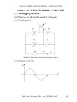
deployment in vehicles by 2008. Figure 2.2 sums up the following progression.
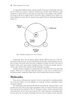
A comprehensive picture of the services to be provided is shown in Figure 2.3.
Road-vehicle communications will be key to providing critical safety information
to vehicles, as well as private-sector information services. Road management is
enhanced by data coming from vehicles. These services and enabling technologies
are expected to complement one another such that a successful business case can be
made for each.
2.2.5 The Netherlands Organization for Scientific Research (TNO) [15]
TNO is a central figure in developing practical short- and long-term implementa
-
tions of cooperative vehicle-highway systems. TNO experts see separate road and
vehicle developments gradually integrating, moving first to a coordination phase
and then to full road-vehicle interaction.
This progression is shown in Figures 2.4–2.6. In each figure, the vertical axis
shows several “waves” of activity: “initiation” referring to pilot testing and initial
deployment phases, “popularization” referring to extending the deployment widely
throughout the road network or vehicle fleet, “management” referring to a mature
and comprehensive implementation of the technology, and “integration and coordi-
nation” in which vehicle and road systems can begin to link with one another.
2.2 Visions for the Future 15
Information infrastructure
(sensing, processing, and provision)
AHSs
Advanced
messaging
support safe driving
Smart Car
Intelligent vehicles
to ensure safety
−2005
Toll and
payment
Read/write
of IC cards
Vehicle
identification
Internet access
Data transfer
Messaging
etc
Next generation DRMs
(detailed, accurate, and dynamic)
Car navigation
system
VICS
Figure 2.2 Japanese Smartway evolution. (Source: NILIM.)
16 Goals and Visions for the Future
Figure 2.3
Japan’s vision for Smartway services. (
Source:
NILIM.)
Road
administrators
Various uses for road
administration
Provide safety
information
coordinated
with maps
Detect
phenomena
that vehicle
cannot
GPS
Car navigation systems
Provision of
information to drivers
Use of vehicle
information
Road
Use of high-volume
two-way
communications
(DSRC)
Variety of
private-sector
information services
Internet, etc.
Service provider
(private sector, etc.)
Utilization of a variety of ITS services
Driver
Provision of
information
from various media
Vehicle
Vehicle-to-vehicle
communication
(future)
Roadside sensor
DSRC
Digital map
ITS onboard unit
Turn right
OOm ahead!!
Accident
km ahead!!∆
You have
In Figure 2.4, the evolution of roadside traffic management is depicted begin
-
ning with the many intelligent transportation measures already implemented, such
as traffic responsive signal timing, coordinated incident management, and elec
-
tronic message signs. These measures then combine as popularisation progresses,
both functionally as well as geographically, to create an intelligent network of high
-
way systems in the 2010 timeframe. At that point, extensive real-time coordination
of roadside systems can be realized.
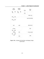
With regard to vehicle systems, the last 10 years or so have seen the initiation
and popularization of various electronic systems in the vehicle that are basically
stand-alone, as shown in Figure 2.5. The current situation is now evolving from sep
-
arate instruments and individual wiring to extensive information networks, a pro
-
cess that TNO estimates will mature around 2010. Advanced driver assistance
systems are seen as coming into broad usage from 2010 through 2020, creating the
opportunity for intelligent road-vehicle interaction.
2.2 Visions for the Future 17
Initiation
Popularization
Management
Integration and
coordination
Phases of growth
Investment (costs)
Current situation separate instruments
and 5 km of copper wire in vehicles
→
Car area networks,
component-based design
ADA
Car radio, car phone, motor management system, ABS
………………
Road-vehicle interaction
possible
2002 2010 2020
Figure 2.5 Evolution of the IV. (Source: TNO.)
2000 2010 2015
Real-time coordination
of measures
Initiation
Popularization
Management
Integration and coordination
Phase of growth
Effect of traffic management
Separate measures
Combination
of measures
Figure 2.4 Evolution of roadside traffic management. (Source: TNO.)
Thus, in the final chart of the series, Figure 2.6, the cooperative intelligent
road-vehicle system emerges as roadside traffic management and in-vehicle systems
mature. Early stages focus on the sharing of information, such as traffic or road con-
ditions ahead, moving onward to real-time road-vehicle interactions. For example, a
collision warning system would automatically adjust the timing of driver warnings
based on information about slippery road conditions ahead, so that the driver would
be alerted sooner if an obstacle were to be detected. Road-vehicle interaction of this
type would culminate around 2020, at which time vehicle-vehicle interactions
would come into play, such as cooperative adaptive cruise control.
2.2.6 France [16]
A more detailed vision of an intelligent road-vehicle future has been developed by
French researchers within their ARCOS program (described further in Chapters 4
and 9). They have defined the concept of “target functions”—driver assistance func
-
tions that could be deployed in incremental steps with supporting research. The
three levels of target functions that have been defined are described below.
Key discriminators between the targets are different levels of technical challenge
and development maturity. Key parameters are information capture capabilities
(e.g., sensing) and an extension of spatial usability (i.e., availability on all or part of
the road network).
Target 1 (Figure 2.7) is basically a combination of autonomous sensing functions
and basic vehicle-vehicle communications. Here, the vehicle has knowledge of braking
capacity, usable longitudinal friction, visibility distance, vehicles ahead in the same lane
(using forward sensing), and downstream hazards (using simple data broadcast tech
-
niques from vehicles ahead). Knowledge of distances and closing rates to both the front
and rear, visibility distance, driver reaction time, local longitudinal road friction, and
vehicle maximum braking capability are combined to create a “risk function.” Driver
warnings or control interventions are based on the risk function.
18 Goals and Visions for the Future
Phases of growth
Effect of traffic management
Roadside traffic management
In-vehicle
traffic management
Road-vehicle information
Road-vehicle interaction
Vehicle-vehicle
interaction
Initiation
Popularization
Management
Integration and
coordination
Interaction
Self-regulation
2020
Figure 2.6 Evolution of a cooperative intelligent road-vehicle system. (Source: TNO.)
Target 2 (Figure 2.8) increases the sensing perimeter and introduces vehi-
cle-highway cooperation. Here, digital maps are at the submetric level, vehicles are
communicating with each other and the roadway, and autonomous sensing capabil-
ities are expanded to create a situational awareness of vehicle activity in both the
current lane and adjacent lanes (using both forward and side sensors). A coopera-
tive infrastructure informs the vehicle about relevant infrastructure elements (e.g.,
guardrails and road edges) and downstream road traction conditions via vehi-
cle-highway communications. Knowledge of road-tire friction is also enhanced by
vehicle-based traction sensors that provide both lateral and longitudinal friction. In
this case, then, the risk function is expanded to include adjacent lane traffic,
2.2 Visions for the Future 19
Road database
2 D attributes
submetric localization
½
Detection/perception
Enhanced autonomous system
V V cooperative systems−
Communication
V V alerts++
I V alerts
−
−
Cooperative roads
Acceptable rules, signals,
positioning systems
Target 2
Figure 2.8 French ARCOS target 2. (Source: LIVIC.)
Current maps
2D geometry/decametric
resolution
Detection/perception
Autonomous systems
Short-distance
One lane
Communication
Vehicle/vehicle
Specific alerts
−
Target 1
Figure 2.7 French ARCOS target 1. (Source: LIVIC.)
two-dimensional road-tire friction, upstream traction conditions, and geometric
characteristics of the road.
Target 3 (Figure 2.9) focuses on spatial extension of cooperative road elements
(i.e., to more roads and types of roads), even more accurate digital maps (if needed),
multisensor fusion, extended vehicle-infrastructure communications, and extended
vehicle-vehicle communications (exchanging information such as vehicle operating
characteristics and maneuver intentions). The perception ability extends quite far
downstream due to the extensive communications network. The risk function then
expands to include both a richer set of data for local conditions and more
extensive downstream information on traffic conditions and the intentions of other
vehicles.
As an example, the three target levels can be considered in terms of a road
departure scenario on a sharply curving road. In target 1, the vehicle has only
forward sensing to rely upon for both forward obstacles and the road edge and no
more than coarse information about the upcoming curve. Therefore, support is
provided via instantaneous sensing to the degree possible as the road curves, with
the look-ahead distance for both driver and sensors limited by the road geometry.
In target 2, the vehicle has precise information as to the upcoming road geometry
due to more detailed digital maps and knowledge of road friction in the curve via
road-vehicle communication. In this case, the driver may be alerted to reduce speed
if the road friction is low. In target 3, due to information sharing along the
roadway, the vehicle is also aware of hazardous downstream events such as
stopped traffic that may be within the curve—a situation beyond the view of
onboard sensors.
Target 1 has immediate safety benefits due to the ability to detect obstacles using
onboard sensing. Target 2 offers higher benefits due to expanded situational aware-
ness and vehicle-infrastructure information exchange—as a result, high-quality
20 Goals and Visions for the Future
Extension of the
cooperative roads
Extension of the enhanced
road database
2 D geometry
Cm localization?
½
Detection/perception
Multisource fusion
Communications:
Extended V V, V I
communication positions,
characteristics,
maneuver parameters
−−
Target 3
Figure 2.9 French ARCOS target 3. (Source: LIVIC.)
information exists as to the situation immediately around the vehicle as well as
conditions downstream on the roadway. However, reaching target 2 functionality
will take time, as roadside communications systems must be deployed and detailed
map databases must be created. In the long term, target 3 shows the potential for
significant gains in both safety and road capacity.
2.2.7 The Cybercar Approach [17]
While most future visions address the proliferation of IV systems in automobiles, an
alternative public vehicle approach is being promoted by the Cybercars project (fur
-
ther described in Chapter 10). Cybercars are characterized as road vehicles (microcar
to minibus to buses) that are capable of low-speed driving automation in urban areas
where their operations are segregated from regular road traffic (for example, in pedes
-
trian-only areas). They operate as highly flexible public personal transport vehicles in
these settings.
The typical evolution to automated driving for private vehicles relies on individ
-
ual cars becoming increasingly more intelligent over the years via onboard sensing
and computing systems. Over the long term, automatic driving becomes possi
-
ble. Their capabilities apply to virtually every road situation encountered by the
vehicle.
The cybercar alternative more or less inverts this process. It begins with fully
automatic vehicles, but their geographic extent is very limited because they operate
in areas segregated from regular traffic. Initially, operations may be in pedestrian
zones or private campus settings. However, as deployments proliferate, operations
zones may be linked and spread across a city. Eventually, intercity tracks can be
implemented as well as automated travel lanes. These road facilities may be
accessed by properly equipped private vehicles, as well, to create a path to full auto-
mation for both public and private vehicles.
2.2.8 Vision 2030 [18]
A visioning and scenario planning process was begun in 1999 by the U.K. Highways
Agency, using a 30-year timescale to encourage forward thinking. As starting points
for the visioning process, three socioeconomic scenarios were created. The first
was called “global economy” and referred to a market-driven approach. The sec
-
ond scenario, “sustainable lifestyle,” focused on community-based living and was
described as “rural bliss in a hi-tech haven.” The third scenario, called “control and
plan,” was based on greater regulation of movement, described as “responsible reg
-
ulated living.” Each of these was described in terms of policy, economic, societal,
technological, legal, and environmental issues.
Within Vision 2030, twelve transport visions were created:
•
Green highway: Strongly environmentally driven;
•
Zero accidents: Assumes strong political support and government action for
safety, relying on extensive deployment of ADAS;
•
The connected customer: Keys on high-quality information to enable manage
-
ment of congested networks and provide real-time and predictive journey
information to travelers;
2.2 Visions for the Future 21
•
Freight foremost: Focuses on a seamless integration of logistics services, as
well as a strong shift from road to rail transport to decrease the numbers of
trucks on the road;
•
Favoring public transport: Calls for reliable, integrated public transport that
can compete with the car; it would include widespread use of automatically
guided buses and/or dedicated transit lanes, and possibly bus platooning;
•
Understanding the customer: Focuses on responsive service and a high-quality
travel experience, sophisticated matching of customer needs with road space,
and proactive traffic management;
•
Easy interchange: Optimizing the role of transport nodes as interchange
points;
•
Institutional change: Requires high levels of performance from the network
operator; to achieve this end, innovation and flexibility are seen as more
important than financial, contractual, and organizational arrangements;
•
Managing supply: Focuses on dynamic allocation of road space, highly auto
-
mated and real-time management of highway transportation, intercity travel
by magnetic levitation trains, and real-time pricing of transportation facilities;
•
Managing demand: Encourages the public to travel less, with road-pricing,
slot allocation, journey booking, and strong enforcement to support these
measures;
•
Cooperative driving on the automated highway system (AHS): AHS tech-
niques used to enable predictable and reliable journey times and segregation of
freight and car traffic;
•
Land use planning: Active planning and development control used to influence
future patterns of supply and demand to achieve sustainable, integrated land use.
Based on expert assessments, three visions were considered promising and rec
-
ommended for further evaluation and analysis:
•
Green highway;
•
Cooperative vehicle-highway systems (drawing upon elements of the coopera
-
tive driving on the AHS vision);
•
Freight foremost.
Analysis of deployment paths to implement various services based on cooperative
vehicle-highway systems is currently under way (see Chapter 9).
2.3 Summary
The “vision zero” concept regarding road fatalities is becoming increasingly popular
and will likely take root globally. Given the way roadway deaths have been accepted as
a fact of life for so many decades, it is both astounding and heartening that such a
vision could be seen as viable. Can our society achieve this goal? An intense partnership
between government and industry is essential, along the lines of the current eSafety
22 Goals and Visions for the Future
program. Consumers, as well, must do their part in choosing to purchase safety equip
-
ment on new cars. Of course, however, any crash is damaging and traumatic, whether
fatal or not—the ideal is to avoid crashes altogether, via the combination of sensing,
information flow, and vehicle intelligence with driver intelligence.
Onboard systems will do the lion’s share of the work in detecting developing
crash situations and taking the proper steps to avoid crashes. In cases where a
hazard is not within the sensor’s field of view, however, information must flow
to the vehicle from either other vehicles or infrastructure sensors. Therefore,
vision zero cannot be achieved without the progression to CVHS depicted by the
NILIM, TNO, and ARCOS visions. CVHS will almost surely require synergy
with private, nonsafety services to create the necessary business momentum for
deployment to proceed.
References
[1] Speech of NHTSA Administrator Jeff Runge at the National IV Initiative Meeting, Society
of Automotive Engineers, June 2003.
[2] The National Road Safety Strategy 2001–2010, Australian Transport Council, Australian
Transport Safety Bureau, Commonwealth Department of Transport and Safety Services,
2000, .
[3] Statement by Prime Minister Junichiro Koizumi (chairman of the Central Traffic Safety Pol-
icy Council) on “Achieving a Reduction to Half the Number of Annual Traffic Accident
Fatalities,” Japanese government, January 2, 2003.
[4] European Road Safety Action Programme: Halving the Number of Road Accident Victims
in the EU by 2010: A Shared Responsibility, European Commission, June 2003.
[5] , accessed May 20, 2004.
[6] 11-Point Program for Improving Road Safety, memorandum April 9, 1999, Swedish Min-
istry of Industry, Employment, and Communications (Regeringskansliet).
[7] Tomorrow’s Roads: Safer for Everyone, U.K. Department for the Environment, Transport
and the Regions (DETR), March 2000, document reference DETR2000e.
[8] 2003 Early Assessment Estimates of Motor Vehicle Crashes, National Center for Statistics
and Analysis, U.S. National Highway Traffic Safety Administration, May 2004.
[10] “Snapshots of U.S. DOT’s Nine New Initiatives,” ITS Cooperative Deployment Network
Newsletter, , accessed May 15, 2004.
[11] Safe Traffic: Vision Zero on the Move, Swedish National Road Administration, 2003.
[12] , accessed May 20, 2004.
[13] Kiyasu, K., “Development of ITS in Japan,” Japanese MLIT, Proceedings of the 7
th
International Task Force on Vehicle-Highway Automation, Paris, 2003 (available via
http:// www.IVsource.net).
[14] Heading Toward the Dream of Driving Safety—AHS, NILIM, Japan, 2004.
[15] van Arem, B., “SUMMITS, Overview of the R&D Program,” TNO Traffic and Transport,
Proceedings of the 7th International Task Force on Vehicle-Highway Automation, Paris,
2003 (available via ).
[16] Blosseville, J. M., “LIVIC Update,” Proceedings of the 6
th
International Task Force on
Vehicle-Highway Automation, Chicago, 2002 (available via ).
[17] Parent, M., “CyberCars Project Review,” National Institute for Research in Information
and Automation (INRIA), Proceedings of the 7
th
International Task Force on Vehicle-High
-
way Automation, Paris, 2003 (available via ).
[18] accessed May 20, 2004.
2.3 Summary 23
CHAPTER 3
IV Application Areas
The range of applications for IV systems is quite broad and applies to all types of
road vehicles—cars, heavy trucks, and transit buses. While there is some overlap
between the functions, and the underlying technology can in some cases support
many functions at once, IV applications can generally be classified into four catego
-
ries: convenience, safety, productivity, and traffic assist.
The following sections describe applications in these areas along with basic
information regarding products and supporting technologies to provide context.
More in-depth information is provided in subsequent chapters.
IV applications can be implemented via autonomous or cooperative sys
-
tems. Autonomous systems rely upon onboard sensors to provide raw data for a
particular application, whereas cooperative systems augment onboard sensor
data with information flowing to the vehicle from an outside source. Using wire-
less communications techniques, this data can be derived from infrastructure
sensors or via information sharing with other vehicles. Data from other vehicles
can be received either directly through vehicle-vehicle communications or
through an innovative technique called floating car data (FCD) or “probe
data.” The FCD concept (further discussed in Chapter 11) relies upon vehicles
reporting basic information relevant to traffic, road, and weather conditions to
a central data center, which is aggregated and processed to develop a highly
accurate picture of conditions across the road network and then disseminated
back to vehicles.
In the discussion below, the reader will gain an applications-level understanding
of how both autonomous and cooperative techniques can be employed.
3.1 Convenience Systems
The term “convenience system” came into being in the late nineties when auto com
-
panies were ready to offer IV driver-assist systems to their customers but were not
yet ready to take on the legal implications and performance requirements that
would come with introducing a new product labeled as a “safety system.” Funda
-
mentally, convenience systems are driver-support products that may assist the
driver in vehicle control to reduce the stress of driving. In some cases these products
are safety-relevant—and drivers commonly consider them to be safety systems—but
they are not marketed as safety systems.
25
3.1.1 Parking Assist
Parking-assist systems help drivers in avoiding the minor “dings” that can come
with parking maneuvers. This is particularly true in urban areas in Europe and
Japan in which parking spaces are very tight.
The simplest form of parking-assist system is a rear-facing video camera, which
offers a view of the area behind the vehicle but no sensing or driver warnings. The
video image is displayed on the driver’s console screen, which otherwise acts as the
navigation display when the vehicle is moving forward. Typically, the rearview
image appears automatically on the screen when the vehicle is shifted into reverse
gear. In this way, the driver can see small objects to the rear and assess distances to
walls and obstacles.
Parking-assist sensor systems generally use ultrasonic sensing of the immediate
area near the car, on the order of 1–2m. More advanced systems use radar to cover
an extended range and provide the driver with more precise information as to the
location of any obstacle. When combined with a rear-looking video display, cali
-
brated scales can be overlaid on the screen to indicate to drivers the precise distance
from an obstacle.
A fascinating form of advanced parking assist was recently introduced by
Toyota, in which the complex steering maneuvers required for parallel parking are
completely automated [1]. When the driver shifts into reverse gear, a rearview
video image is displayed. Overlaid on this image is a rectangle that is sized to
represent the host vehicle. The driver uses arrow keys to position this rectangle over
the desired parking space within the image. After a “set” key is pressed, the
driver is instructed to proceed by operating the accelerator and brakes, while the
system takes care of steering to maneuver the vehicle precisely into the parking
space.
3.1.2 Adaptive Cruise Control (ACC)
The primary convenience system currently available for highway driving is ACC.
ACC allows a driver to set a desired speed as in normal cruise control; if a vehicle
immediately ahead of the equipped vehicle is moving at a slower speed, then throttle
and braking of the host vehicle is controlled to match the speed of the slower vehicle
at a driver-selectable time headway, or gap. The desired speed is automatically
reattained when the roadway ahead is unobstructed, either from the slower vehicle
ahead leaving the lane or the driver of the host vehicle changing to a clear lane.
These operating modes are illustrated in Figure 3.1. Systems currently on the market
monitor the forward scene using either radar or lidar (laser radar); future systems
may also use machine vision.
Current generation ACC systems operate only above a speed threshold on the
order of 40 km/hr. The braking authority of the system is limited; if the host vehicle
is closing very rapidly on a vehicle ahead and additional braking is needed to avoid a
crash, the driver is alerted to intervene.
Users generally report that the system substantially reduces the tedium of
braking and accelerating in typical highway traffic, in areas where conven
-
tional cruise control is all but unusable due to the density of the surrounding
traffic.
26 IV Application Areas
3.1.3 Low-Speed ACC
Low-speed ACC is an evolution of ACC functionality, which operates in slow, con-
gested traffic to follow the car immediately ahead. When traffic clears and speeds
return to normal, conventional ACC would then be used. This type of product is
sometimes called “stop-and-go ACC.” Early versions may only perform a “stop
and wait” function, requiring that the driver initiate a resumption of forward
movement when appropriate. This is because manufacturers are hesitant to offer a
system that automatically starts from a stop in complex low-speed traffic environ-
ments, which may include pedestrians. Other low-speed ACC systems operate
down to a very low speed (approximately 5 km/hr) and then require the driver to
intervene if needed to both stop and restart vehicle motion. Low-speed ACC was
introduced to the Japanese market in 2004.
3.1.4 Lane-Keeping Assistance (LKA)
LKA offers a “copilot” function to drivers in highway environments. Research has
shown that the many minute steering adjustments that must be made by drivers on
long trips are a significant source of fatigue. LKA uses machine vision technology to
detect the lane in which the vehicle is traveling, and steering actuation to add torque
to the steering wheel to assist the driver in these minute steering adjustments. The
experience can be imagined as similar to driving in a trough, such that the curving
vertical sides of the trough create a natural steering resistance to keep the vehicle in
the center. As the developers are fond of saying, the experience is “like driving in a
bathtub.”
Lane-keeping systems generally are set to operate only at the speeds and typical
curvatures of major highways, such as the U.S. interstate highway system or major
motorways in Europe and Japan. The system will disengage if sharp curves are
encountered. Further, the driver must continue to provide steering inputs; otherwise
the system will sound an alarm and turn off—this is to ensure that drivers are not
tempted to use it as a “hands-off” system.
3.1 Convenience Systems 27
Constant speed
100 km/h
100 km/h
100 km/h 100 km/h 100 km/h
80 km/h 100 km/h→100 km/h 80 km/h→
80 km/h
80 km/h
80 km/h
AccelerateFollowDecelerate
Operation of adaptive cruise control (ACC)
Figure 3.1 Operating modes for ACC. (Source: Nissan.)
More advanced versions of LKA could conceivably allow for full automatic
“hands-off” steering, but driver vigilance issues would have to first be worked out.
3.1.5 Automated Vehicle Control
While still quite far in the future, the ultimate in “driving convenience” for many
would be the proverbial “car that drives itself.” While the joy of driving is
unmatched on a winding mountain road on a sunny day, daily driving is an experi
-
ence that typically fatigues, frustrates, and frazzles us as drivers. To have the alterna
-
tive of handing control of the vehicle over to a trustworthy technology agent is quite
attractive. Prototype vehicles of this type have been developed and demonstrated,
and professionals knowledgeable in automotive technology generally agree that
self-driving cars are inevitable some time within the next few decades.
An early form of automated vehicle control likely to be very popular is low-speed
automation (LSA). This application simply combines full-function low-speed ACC
with full hands-off lane keeping to completely take care of the driving task in congested
traffic. Conceptually, the system would alert the driver to resume control of the vehicle
when the traffic clears and speeds increase to normal. Various forms of LSA are cur
-
rently in the R&D stage.
3.2 Safety Systems
As noted in Chapter 2, traffic fatalities range into the tens of thousands in developed
countries and the numbers of crashes are in the millions. Given the massive societal
costs, governments are highly motivated to promote active safety systems for crash
avoidance.
Further, based on experience with airbag systems, it has been well established
that “safety sells” in the automotive showroom, and therefore automotive manufac
-
turers have a good business case for offering active safety systems on new cars.
Active safety system applications within the IV realm are many and varied.
From the following list of collision countermeasures (also described in the following
sections), it can be seen that virtually every aspect of vehicle crashes is represented:
•
Assisting driver perception;
•
Adaptive headlights;
•
Night vision;
•
Animal warning;
•
Headway advisory;
•
Crash prevention;
•
Forward collision warning/mitigation/avoidance;
•
Lane departure warning;
•
Lane/road departure avoidance;
•
Curve speed warning;
•
Side object warning (blind spot);
•
Lane change support;
28 IV Application Areas
•
Rollover countermeasures;
•
Intersection collision countermeasures;
•
Rear impact countermeasures;
•
Backup/parking assist;
•
Pedestrian detection and warning;
•
Degraded driving;
•
Driver impairment monitoring;
•
Road surface condition monitoring;
•
Precrash;
•
Prearming airbags;
•
Occupant sensing (to inform airbag deployment);
•
Seatbelt pretensioning;
•
Precharging of brakes;
•
External vehicle speed control.
3.2.1 Assisting Driver Perception
IV systems can enhance the driver’s perception of the driving environment, leaving any
interpretation or action to the driver’s judgment. Adaptive headlights provide better
illumination when the vehicle is turning; night vision provides an enriched view of the
forward scene; roadside systems can alert drivers to the presence of wildlife; and head-
way advisory provides advice to the driver regarding following distance.
Adaptive Front Lighting (AFS) Adaptive headlights illuminate areas ahead and to
the side of the vehicle path in a manner intended to optimize nighttime visibility for
the driver. Basic systems, already on the market, take into account the vehicle speed
to make assumptions as to the desired illumination pattern. For instance, beam
patterns adjust down and outward for low-speed driving, while light distribution is
longer and narrower at high speeds to increase visibility at farther distances. More
advanced systems also incorporate steering-angle data and auxiliary headlights on
motorized swivels. In the case of a vehicle turning a corner, for example, the outer
headlight maintains a straight beam pattern while the inner, auxiliary headlight
beam illuminates the upcoming turn. The system aims to automatically deliver a
light beam of optimal intensity to maximize the illumination of oncoming road
curves and bends. Next generation adaptive lighting systems will use satellite
positioning and digital maps so as to have preview information on upcoming
curves. Headlights are then aimed into the curve even before the vehicle reaches the
curve, at just the right point in the maneuver, to present the driver an optimal view.
Night Vision Night vision systems help the driver see objects such as pedestrians
and animals on the road or the road edge, far beyond the view of the vehicle’s
headlights. Typically this is displayed via a heads-up display. Advanced forms of
night vision process the image to identify potential hazards and highlight them on
the displayed image.
Animal Warning Obviously, not all cars have night vision systems. To provide
alerts to wildlife near roads for all drivers, road authorities are experimenting with
3.2 Safety Systems 29
roadside sensors that detect wildlife such as deer and elk in areas where they are
known to be frequently active. If animals are present, drivers are advised by
electronic signs as they approach the area.
Headway Advisory The headway advisory function, also called safe gap advisory,
monitors the distance and time headway to a preceding vehicle to provide
continuous feedback to the driver. Gap thresholds can be applied to indicate to the
driver when safety is compromised. Fundamentally, headway advisory performs the
sensing job of ACC without the automatic control.
3.2.2 Crash Prevention
The following sections describe crash prevention systems in various stages of devel
-
opment. Some are in the R&D stages, while others have been introduced to the pub
-
lic as optional equipment on new cars.
Forward Collision Warning/Mitigation/Avoidance IV safety systems augment the
driver’s monitoring of the road and traffic conditions to detect imminent crash
conditions. Systems to prevent forward collisions rely on radar or lidar sensing,
sometimes augmented by machine vision. Basic systems provide a warning to the
driver, using a variety of means such as audible alerts, visual alerts (typically on
a heads-up display), seat vibration, or even slight seat-belt tensioning to provide
a haptic cue. More advanced systems add automatic braking of the vehicle if the
driver is not responding to the situation. An initial version of active braking
systems is termed “collision mitigation system.” These systems primarily defer
to the driver’s control; braking serves only to reduce the impact velocity of a
collision if the driver is not responding appropriately to an imminent crash
situation. Collision mitigation systems were originally introduced to the market
in Japan in 2003. The next functional level, forward collision avoidance,
represents the ultimate crash avoidance system, in which sufficient braking is
provided to avoid the crash altogether.
Lane Departure Warning Systems (LDWS) LDWS use machine vision techniques to
monitor the lateral position of the vehicle within its lane. Computer algorithms
process the video image to “see” the road markings and gauge the vehicle’s position
within them. The driver is warned if the vehicle starts to leave the lane inadvertently
(i.e., turn signal not activated). A favored driver interface is to emulate the “rumble
strip” experience by providing a low rumbling sound on the left or right audio
speaker, as appropriate to the direction of the lane departure. LDWS were initially
sold in the heavy truck market; they were first introduced to the public in Japan and
entered the European and U.S. automobile markets in 2004.
Lane/Road Departure Avoidance (RDA) Lane departure avoidance systems go one
step farther than LDWS by providing active steering to keep the vehicle in the lane
(while alerting the driver to the situation). In the case of RDA, advanced systems
assess factors such as shoulder width to adjust the driver alert based on the criticality
of the situation. For instance, a vehicle drifting onto a wide, smooth road shoulder
is a relatively benign event compared to the same situation with no shoulder.
Prototypes of such RDA systems are currently being evaluated.
30 IV Application Areas
Curve Speed Warning Curve speed warning is another form of road departure
avoidance that uses digital maps and satellite positioning to assess a safe speed
threshold for an upcoming curve in the roadway. The driver is warned if speed is
excessive as the vehicle approaches the curve. Prototypes of curve speed warning
systems have been built and evaluated.
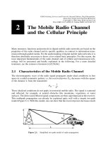
Side Object Warning Side object monitoring systems assist drivers in changing
lanes by detecting vehicles in the “blind spot” to the left rear of the vehicle (or right
rear for countries such as Japan with right side driver positions and left-hand road
driving). Blind spot monitoring using radar technology has been used by truckers in
the United States for many years and is expected to enter the automobile market
soon. Figure 3.2 shows detection zones for side object awareness, as well as other
applications. This is a good example of “bundling” such applications.
Lane Change Support Lane change support systems extend monitoring beyond
the blind spot to provide rearward sensing to assist drivers in making safe lane
changes. Advanced systems also look far upstream in adjacent lanes to detect fast
approaching vehicles that may create a hazardous situation in the event of a lane
change. This is especially important on high-speed motorways such as the German
Autobahn. These systems are in the advanced development phase.
Rollover Countermeasures Rollover countermeasures systems are designed to
prevent rollovers by heavy trucks. While electronic stability control to avoid
rollovers of passenger cars is becoming widely available, the vehicle dynamics for
tractor trailers are very different—the truck driver is unable to sense the initial
trailer “wheels-up” condition that precedes a rollover, and rollover dynamics
change with the size and consistency of the cargo. Rollover countermeasure systems
approximate the center of gravity of the vehicle and dynamically assess the
combination of speed and lateral acceleration to warn the driver when close to a
3.2 Safety Systems 31
Multifeature
rear sector safety zone
Tailgate alert
Enhanced
back-up
aid
Side object
awareness
Side object
awareness
Rear
cross
path
Rear
cross
path
Park
aid
Figure 3.2 Detection zones for side object awareness and other applications. (Source: Visteon.)