Tài liệu Handbook of Machine Design P46 ppt
Bạn đang xem bản rút gọn của tài liệu. Xem và tải ngay bản đầy đủ của tài liệu tại đây (508.02 KB, 27 trang )
CHAPTER
39
A
THESAURUS
OF
MECHANISMS
L.
E.
Torfason
Profesor
of
Mechanical
Engineering
University
of
New
Brunswick
Fredericton,
Canada
GLOSSARY
OF
SYMBOLS
R
Revolute
pair
or pin
joint
P
Prismatic pair
or
sliding joint
C
Cylinder pair
for
joints that allow rotation
and
sliding along
the
cylinder
axis
G
Spheric pair (globe)
for
ball joints
S
L
Screw pair with lead
L
F
Planar pair
(flat)
for a
joint that maintains
two
planes
in
contact
SUMMARY*
This chapter
is
intended
to be
used
as an
idea generator. Following
the
adage that
a
picture
is
worth 1000 words, this chapter
was
assembled with millions
of
"words"
in
figures
and
virtually none using
the
alphabet.
I
have taken
the
liberty
of
varying
dimensions
to
better show
the
principle
of
operation.
You
should
not
scale
the
fig-
ures,
but
follow
the
regular synthesis procedure
to
determine
the
proper
dimensions
for
the
application
in
mind.
In
this chapter
a new
notation
is
used
for the
kinematic representation
of
joints
or
pairs
in a
linkage.
^
Readers
will
note
a
difference
in the
style
and
character
of the
figures
in
this chapter. When this
manuscript
was
received,
the
illustrations,
all
conceived
and
executed
by
Professor
Torfason,
were seen
to be
original
and
unique.
We
asked
for and
received
from
the
publishers special permission
to
reproduce them
exactly
as
they were
drawn—EDS.
COLLATERAL
READING
L. J.
Kamm, Designing
Cost-Efficient
Mechanisms,
McGraw-Hill,
New
York, 1990.
FIGURE
39.1 Snap-action mechanisms. These mechanisms
are
bistable elements
in
machines.
They
are
used
in
switches
to
quickly make
and
break electric circuits
and for
fastening items.
(a)
Snap-action toggle switch;
(b) to
(H)
seven variations
of
snap-action switches;
(i)
circuit breaker;
(J)
to
(o), spring clips.
FIGURE 39.2 Linear actuators.
These
are
devices that cause
a
straight-line displacement
between
two
machine
elements,
(a)
Lead
screw;
(b)
worm gear with stationary nut;
(c)
worm
gear with stationary screw;
(d)
single-acting hydraulic cylinder;
(e)
double-acting hydraulic
cylinder;
(/)
telescoping
hydraulic cylinder;
(g)
hydraulic cylinder with positional feedback;
(h)
hydraulic cylinder with floating link feedback.
FIGURE 39.3 Fine adjustments
I.
Fine
adjustments
for
stationary mechanisms
are
mechanisms
that make
a
small change
in the
position
of a
mechanical
member,
(a),
(b)
Screw adjustments;
(c),
(d)
differential
screws;
(e)
Chinese windlass;
(/)
differential
hoist;
(g)
worm gear
and
screw;
(h)
worm gears
in
series;
(i)
lever;
(J)
levers
in
series;
(k)
toggle mechanism;
(/)
screws
to
adjust
angular position; (m),
(n)
eccentric
cranks;
(o)
wedges;
(p)
harmonic drive.
FIGURE 39.4 Fine adjustments
II.
Fine adjustments
for
moving mecha-
nisms
are
adjusting devices which control
the
motion
of
linkages such
as
stroke, etc., while
the
mechanism
is in
motion,
(a),
(b)
Differential gear
adjustment;
(c)
adjustable-stroke engine;
(d)
adjustable stroke
of
shaper
mechanism;
(e)
ball
and
disk speed changer;
(/)
adjusting
fixed
center
of
linkage
for
changing motion properties.
FIGURE 39.5 Clamping mechanisms. These devices
are
used
to
hold items
for
machining
operations
or to
exert great forces
for
embossing
or
printing,
(a) C
clamp;
(b)
screw clamp;
(c) cam
clamp;
(d)
double
cam
clamp;
(e)
vise;
(/)
cam-operated clamp;
(g)
double
cam-
actuated clamp;
(h)
double wedge;
(i)
to
(/)
toggle press;
(m)
vise grips;
(n)
toggle clamp;
(0)
collet;
(P)
rock crusher.
FIGURE 39.6 Locating mechanisms.
These
are
devices which properly posi-
tion
a
linkage member when
the
load
is
removed,
(a) to (/)
Self-centering lin-
ear
devices;
(g) to
(n)
self-centering angular devices;
(o)
detent.
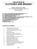
FIGURE
39.7 Escapements. These devices slowly release
the
potential energy
stored
in a
spring
to
control devices such
as
clocks,
(a)
Paddle wheel;
(b)
recoil
escapement;
(c)
dead-beat escapement;
(d)
stud escapement;
(e)
early anchor
escapement;
(/)
cylinder escapement;
(g)
double three-legged escapement
for
tower
clocks;
(h)
to
(/)
chronometer escapements;
(k)
fuse
used
to
give
uniform
torque
at
escapement
as the
spring unwinds.
FIGURE 39.8 Indexing mechanisms. These mechanical devices advance
a
body
to a
specific
position, hold
it
there
for a
period,
and
then advance
it
again.
(a)
to
(c)
Geneva stops;
(d)
four-bar
links used
to
reduce jerk;
(e)
ratchet
mechanism;
(/)
friction
ratchet;
(g)
cylindrical cam-stop mechanism;
(h) pin
gearing used
in
indexing;
(i)
dividing head.
FIGURE 39.9 Oscillating mechanisms
I.
These mechanisms cause
an
output
to
repeatedly swing
through
a
preset
angle,
(a)
Four-bar linkage;
(b)
six-bar linkage;
(c)
six-bar linkage with
pin in
slot;
(d)
inverted slide-crank quick-return linkages;
(e)
radial
cam and
follower;
(/)
cylindrical cam;
(g)
geared slider crank;
(h)
geared inverted slider crank;
(/)
slider-driven crank;
(J)
bulldozer
lift
mechanism;
(k)
oscillator
of the
Corliss valve gear.
FIGURE
39.10 Oscillating mechanisms
II.
These
all use
spatial linkages.
(a)
Spatial
pin and
yoke;
(b)
spherical four-bar linkage;
(c)
spatial RGGR
linkage;
(d)
spatial RCCC;
(e)
spatial RRGRR;
(/)
spatial RRGC.
FIGURE
39.11 Ratchets
and
latches.
These
are
mechanisms that advance
or
hold
a
machine
member,
(a)
Ratchet
and
pawl;
(b)
reversible ratchet;
(c)
cam-lock ratchet;
(d)
ball-lock ratchet;
(e)
toggle ratchet;
(/)
overrunning clutch;
(g)
high-torque ratchet;
(/*),
(i)
detents;
(/)
locking bolts.
FIGURE 39.12 Reciprocating mechanisms
I.
These mechanical devices cause
a
member
to
trans-
late
on a
straight
line,
(a)
Slider crank;
(b)
Scotch yoke;
(c)
toggle mechanism;
(d)
Zoller
engine;
(e)
V
engine;
(/)
double-stroke engine;
(g)
geared engine;
(h)
Atkinson
gas
engine;
(i)
ideal radial
engine;
(/)
practical radial engine;
(A:)
geared Nordberg radial engine;
(/)
linked Nordberg radial
engine.
FIGURE
39.13 Reciprocating mechanisms
II. (a)
Geared
cranks;
(b)
shaper mechanism;
(c)
slider
on
Whitworth
quick-return mechanisms;
(d)
slider
on
drag-link mechanism;
(e)
variable-stroke
engine;
(/)
gear-driven slider.
FIGURE 39.14
Reversing
mechanism.
These
mechanical devices change
the
direction
of
rotation
of
the
output,
(a)
Reversible prime movers;
(b)
reversing gears;
(c)
reversing belts;
(d)
transmission;
(e)
epicyclic gears
as in
Model
T
Ford.
FIGURE 39.15 Couplings
and
connectors—axial.
These
are
used
to
connect
co-
axial
shafts,
(a)
Rigid coupling;
(b) flanged
coupling;
(c)
disk clutch;
(d)
cone
clutch;
(e)
plate clutch.
FIGURE
39.16
Couplings
and
connectors—parallel
shafts,
(a)
Flat belt;
(b) V
belt;
(c)
chain;
(d)
to
(/)
gears;
(g)
Hooke joints;
(H)
Oldham coupling;
(i)
Hunt's
constant-
velocity
coupling;
(/)
drag
link;
(k)
to
(rri)
flexible
coupling.
FIGURE 39.17 Couplings
and
connectors—intersecting
shafts,
(a)
Bevel gears;
(b)
flat
belts with idlers;
(c)
Hooke
joint;
(d)
Hooke's
coupling;
(e)
Clemens
coupling;
(/)
Rouleaux coupling;
(g)
spatial RCCR;
(h)
Hunt's constant-velocity
coupling.
FIGURE 39.18 Couplings
and
connectors—skew
shafts,
(a)
Flat
belts;
(b)
spatial
RCCR;
(c)
flex-
ible
shaft;
(d)
hypoid gears;
(e)
spatial
RGGR.
FIGURE 39.19
Slider
connectors.
These
devices connect
two or
more reciprocating devices.
(a)
Elliptic trammel;
(b)
gears;
(c)
slider-crank-slider;
(d)
cable;
(e)
hydraulic;
(/)
helical gearing.
FIGURE
39.20 Stops, pauses,
and
hesitations. These machine ele-
ments
cause
an
output
to
stop
and
dwell,
to
stop
and
return,
to
stop
and
advance,
etc.
The
derivatives
of the
motion
at the
stop
determine which
category
the
motion
fits,
(a)
Geneva stops (this includes
all
motions
in
Fig.
39.8);
(b)
cams;
(c)
linkage
at
extreme limits; (d),
(e)
combination
of
linkages
at a
limit; (/),
(g)
outputs derived
from
coupler curves.
FIGURE 39.21 Transportation
devices.
These mechanisms move
one or
more
objects
a
discrete distance
in
stepped
motion,
(a)
Four-bar
film
advance;
(b)
circular-
motion transport;
(c),
(d)
coupler-curve transport;
(e)
geared linkage transport;
(/)
fishing-reel
feed.
FIGURE 39.22 Loading
and
unloading mechanisms
I.
These mechanisms pick
up
material
and
transport
it to
another
location,
(a) to (c)
Front-end loaders;
(d)
back hoe;
(e),
(/)
clamshell loaders.
FIGURE
39.23
Loading
and
unloading mechanisms
II.
(a),
(b)
Mucking machines;
(c)
scooping mechanism;
(d)
to (/)
dumping mine cars;
(g)
to (i)
dump trucks;
(J)
motor
scraper;
(k)
elevating
scraper.
FIGURE
39.24 Path generators.
These
linkages approximately generate
a
required
curve,
(a)
Four-bar coupler curve;
(b)
Watt straight-line linkage;
(c)
Crosby steam-
engine
indicator approximates straight line;
(d)
scooping mechanism;
(e)
Peaucellier
exact
straight-line linkage;
(/)
geared straight-line generators;
(g)
six-bar coupler
curve;
(h)
double-cam line generator;
(i)
pantograph;
(;')
Sylvester skew pantograph;
(k)
geared linkage curve generator.
FIGURE 39.25 Function
generators.
These
are
mechanical devices
in
which
the
output moves
as
some function
of the
input
y =
f(x).
(a)
Four-bar linkage
function
generator;
(b)
function
generator
in
pressure gauge;
(c),
(d)
function
generator
in a
speedometer;
(e)
Scotch yoke sine-cosine generator;
(/)
epicyclic
sine-cosine generator;
(g)
noncircular gears.
FIGURE 39.26 Computing mechanisms. These devices
are
used
on
mechanical computers
for
performing mathematical
operations,
(a)
Ball
disk
integrator;
(b)
multiplier;
(c),
(d)
adders;
(e)
epicyclic sine genera-
tors;
(/)
Scotch yoke sine generator;
(g)
noncircular gears;
(h)
special-
function
cams.