Tài liệu Handbook of Machine Design P43 doc
Bạn đang xem bản rút gọn của tài liệu. Xem và tải ngay bản đầy đủ của tài liệu tại đây (765.54 KB, 22 trang )
CHAPTER
36
WORM
GEARING
K.
S.
Edwards,
Ph.D.
Professor
of
Mechanical
Engineering
University
of
Texas
at El
Paso
El
Paso,
Texas
36.1 INTRODUCTION
/
36.2
36.2 KINEMATICS
/
36.3
36.3 VELOCITY
AND
FRICTION
/
36.5
36.4
FORCE
ANALYSIS
/
36.5
36.5 STRENGTH
AND
POWER RATING
/
36.9
36.6 HEAT DISSIPATION
/
36.12
36.7 DESIGN STANDARDS
/
36.13
36.8 DOUBLE-ENVELOPING GEAR SETS
/36.18
REFERENCES
/
36.22
ADDITIONAL
REFERENCE
/
36.22
GLOSSARY
OF
SYMBOLS
b
G
Dedendum
of
gear teeth
C
Center distance
d
Worm pitch
diameter
d
0
Outside diameter
of
worm
d
R
Root diameter
of
worm
D
Pitch diameter
of
gear
in
central plane
D
b
Base circle diameter
D
0
Outside diameter
of
gear
D
1
Throat diameter
of
gear
/
Length
of flat on
outside diameter
of
worm
h
k
Working depth
of
tooth
h
t
Whole depth
of
tooth
L
Lead
of
worm
m
G
Gear ratio
=
N
G
IN
W
m
0
Module, millimeters
of
pitch diameter
per
tooth
(SI
use)
m
p
Number
of
teeth
in
contact
n
w
Rotational speed
of
worm, r/min
n
G
Rotational speed
of
gear, r/min
N
0
Number
of
teeth
in
gear
NW
Number
of
threads
in
worm
p
n
Normal circular pitch
p
x
Axial circular pitch
of
worm
P
Transverse diametral pitch
of
gear, teeth
per
inch
of
diameter
W
Force
between worm
and
gear (various components
are
derived
in the
text)
X
Lead angle
at
center
of
worm,
deg
tyn
Normal pressure angle,
deg
§
x
Axial pressure angle, deg,
at
center
of
worm
36.7 INTRODUCTION
Worm
gears
are
used
for
large speed reduction with concomitant increase
in
torque. They
are
limiting cases
of
helical gears,
treated
in
Chap.
35. The
shafts
are
normally
perpendicular, though
it is
possible
to
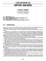
accommodate other angles. Con-
sider
the
helical-gear pair
in
Fig.
36.Ia
with
shafts
at
90°.
The
lead angles
of the two
gears
are
described
by
X
(lead angle
is 90°
less
the
helix
angle).
Since
the
shafts
are
perpendicular,
X
1
+
X
2
=
90°.
If the
lead angle
of
gear
1 is
made small enough,
the
teeth eventually wrap completely around
it,
giving
the
appearance
of a
screw,
as
seen
in
Fig.
36.1Z?.
Evidently this
was at
some stage taken
to
resemble
a
worm,
and the
term
has
remained.
The
mating member
is
called sim-
ply
the
gear,
sometimes
the
wheel.
The
helix angle
of the
gear
is
equal
to the
lead
angle
of the
worm (for
shafts
at
90°).
The
worm
is
always
the
driver
in
speed reducers,
but
occasionally
the
units
are
used
in
reverse fashion
for
speed increasing. Worm-gear sets
are
self-locking when
the
gear cannot drive
the
worm. This occurs when
the
tangent
of the
lead angle
is
less
than
the
coefficient
of
friction.
The use of
this feature
in
lieu
of a
brake
is not
rec-
FIGURE 36.1
(a)
Helical gear pair;
(b)
a
small lead angle causes gear
one to
become
a
worm.
-GEAR
2(GEAR,
OR
WHEEL)
GEAR
1
(WORM)
GEAR
!(DRIVER,
\
TEETH)
MATING
TEETH
GEAR
2(N
Q
TEETH)
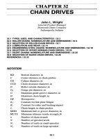
FIGURE
36.2
Photograph
of a
worm-gear
speed
reducer.
Notice that
the
gear partially
wraps,
or
envelopes,
the
worm. (Cleveland Worm
and
Gear Company.)
ommended, since under running condi-
tions
a
gear
set may not be
self-locking
at
lead angles
as
small
as 2°.
There
is
only point contact between
helical gears
as
described above. Line
contact
is
obtained
in
worm gearing
by
making
the
gear envelop
the
worm
as
in
Fig. 36.2; this
is
termed
a
single-
enveloping
gear
set,
and the
worm
is
cylindrical.
If the
worm
and
gear
envelop each other,
the
line contact
increases
as
well
as the
torque that
can
be
transmitted.
The
result
is
termed
a
double-enveloping
gear
set.
The
minimum number
of
teeth
in the
gear
and the
reduction ratio determine
the
number
of
threads (teeth)
for the
worm.
Generally,
1 to 10
threads
are
used.
In
special cases
a
larger number
may
be
required.
36.2 KINEMATICS
In
specifying
the
pitch
of
worm-gear sets,
it is
customary
to
state
the
axial
pitchy
of
the
worm.
For 90°
shafts
this
is
equal
to the
transverse circular pitch
of the
gear.
The
advance
per
revolution
of the
worm, termed
the
lead
L,
is
L=p
x
N
w
This
and
other
useful
relations result
from
consideration
of the
developed pitch
cylinder
of the
worm, seen
in
Fig. 36.3. From
the
geometry,
the
following
relations
can be
found:
d
=
^-
(36.1)
n
sin
A
FIGURE 36.3
Developed
pitch cylinder
of
worm.
rf
=
^V
(
36
-
2
>
TI
tan
X
^
'
tan
^
=
4
=^r
(363)
nd nd
^=Wi
<
36
-
4
>
Z)=
M£
=
J^
V
71 71
COS A
From Eqs.
(36.1)
and
(36.5),
we
find
taia=
^
=
_LS
(36
.
6)
N
G
d
m
c
d
The
center distance
C can be
derived
from
the
diameters
c
=
P^
I
Jn^
+
1
\
271
\cosA,
sin
X/
v
'
which
is
sometimes more
useful
in the
form
2TiC
—-—
U.S. customary units
PnN
W
-^
+
-V-I
A
f
C
,
SI
units (36.8)
cos A
sin
A
m
0
N
w
cos A
2C
,
.
.
either
a
sin
A
For use in the
International System (SI), recognize that
Np
x
Diameter
=
Nm
0
=
TC
so
that
the
substitution
p
x
=
nm
0
will
convert
any of the
equations above
to SI
units.
The
pitch diameter
of the
gear
is
measured
in the
plane containing
the
worm axis
and is, as for
spur gears,
D
=
^
(36.9)
The
worm pitch diameter
is
unrelated
to the
number
of
teeth.
It
should, however,
be the
same
as
that
of the hob
used
to cut the
worm-gear tooth.
36.3
VELOCITYANDFRICTION
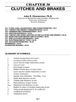
Figure 36.4 shows
the
pitch line velocities
of
worm
and
gear.
The
coefficient
of
fric-
tion between
the
teeth
\JL
is
dependent
on the
sliding velocity. Representative values
of
|i
are
charted
in
Fig. 36.5.
The
friction
has
importance
in
computing
the
gear
set
efficiency,
as
will
be
shown.
36.4
FORCEANALYSIS
If
friction
is
neglected, then
the
only force exerted
by the
gear
on the
worm will
be
W,
perpendicular
to the
mating tooth surface, shown
in
Fig. 36.6,
and
having
the
three components
W,
W, and
W
z
.
From
the
geometry
of the
figure,
W = W
cos(|)
n
sin
A,
W =
W
sin
(^
n
(36.10)
W
z
= W cos ty
n
cos K
In
what
follows,
the
subscripts
W and G
refer
to
forces
on the
worm
and the
gear.
The
component
W is the
separating,
or
radial, force
for
both worm
and
gear (oppo-
site
in
direction
for the
gear).
The
tangential force
is
W*
on the
worm
and
W
z
on the
gear.
The
axial force
is
W
z
on the
worm
and
W*
on the
gear.
The
gear forces
are
oppo-
site
to the
worm forces:
W
Wt
=
-W
Ga
=
W
W
Wr
=
-W
Gr
=
W
(36.11)
W
Wa
=
-W
Gt
=
W
FIGURE 36.4 Velocity
components
in a
worm-gear set.
The
sliding
velocity
is
V
s
=
(V
2
.
T/
2
V/2
V
w
(Vw
+
VG)
T-
cos
X
AXIS
OF
WORM
GEAR
TOOTH
AXIS
OF
GEAR
ROTATION
SLIDING
VELOCITY,
fpm
FIGURE 36.5 Approximate
coefficients
of
sliding friction between
the
worm
and
gear
teeth
as a
function
of the
sliding velocity.
All
values
are
based
on
adequate lubrication.
The
lower curve represents
the
limit
for the
very best materials, such
as a
hardened worm
meshing with
a
bronze gear.
Use the
upper curve
if
moderate
friction
is
expected.
FIGURE 36.6 Forces exerted
on
worm.
PITCH
CYLINDER
OF
WORM
PITCH
HELIX
COEFFICIENT
OF
FRICTION.
where
the
subscripts
are t for the
tangential direction,
r for the
radial direction,
and
a
for the
axial direction.
It is
worth noting
in the
above equations that
the
gear axis
is
parallel
to the x
axis
and the
worm axis
is
parallel
to the z
axis.
The
coordinate sys-
tem is
right-handed.
The
force
W,
which
is
normal
to the
profile
of the
mating teeth, produces
a
fric-
tional force
W
f
=
\iW,
shown
in
Fig. 36.6, along with
its
components
\iW
cos A in the
negative
x
direction
and
\\W
sin X in the
positive
z
direction. Adding these
to the
force
components developed
in
Eqs.
(36.10)
yields
W
x
=
W(CQS
fa sin
X
+
|i
cos
X)
W = W
sin
fa
(36.12)
W
z
=
W(cos
fa
CQS
A,
-
Ji
sin
A,)
Equations
(36.11)
still apply. Substituting
W
z
from
Eq.
(36.12) into
the
third
of
Eqs.
(36.11)
and
multiplying
by
Ji,
we
find
the
frictional force
to be
W
f
=[iW=
.
.
^
W
°<
(36.13)
|U
sin
A - cos fa cos A
A
relation between
the two
tangential forces
is
obtained
from
the
first
and
third
of
Eqs.
(36.11)
with appropriate substitutions
from
Eqs. (36.12):
cos^nK^cosK
(i
sin
A
- cos fa cos A
The
efficiency
can be
defined
as
_
W
W[
(without
friction)
11=1
W
Wt
(with
friction)
(
'
Since
the
numerator
of
this equation
is the
same
as Eq.
(36.14) with
\i
=
O,
we
have
cos^-ntanX
COS
fa +
JLl
COt A
Table 36.1 shows
how
TJ
varies with
X,
based
on a
typical value
of
friction
|i
=
0.05
and
the
pressure angles usually used
for the
ranges
of
A,
indicated.
It is
clear that small
A,
should
be
avoided.
Example
1. A
2-tooth right-hand worm transmits
1
horsepower (hp)
at
1200 revo-
lutions
per
minute (r/min)
to a
30-tooth gear.
The
gear
has a
transverse diametral
pitch
of 6
teeth
per
inch.
The
worm
has a
pitch diameter
of 2
inches (in).
The
normal
pressure angle
is
14
1
^
0
.
The
materials
and
workmanship correspond
to the
lower
of
the
curves
in
Fig. 36.5. Required
are the
axial pitch, center distance, lead, lead angle,
and
tooth
forces.
Solution.
The
axial pitch
is the
same
as the
transverse circular pitch
of the
gear.
Thus
p
x
= — =
—
=
0.5236
in
TABLE
36.1
Efficiency
of
Worm-Gear Sets
for
\i
=
0.05
Normal
pressure
angle
Lead
angle
X,
Efficiency
17,
4
n
,
deg deg
percent
14*
1
25.2
2.5
46.8
5
62.6
7.5
71.2
10
76.8
15
82.7
20
20
86.0
25
88.0
30
89.2
The
pitch diameter
of the
gear
is D =
N
0
IP
=
30/6
= 5 in. The
center distance
is
thus
„
D+d 2+5
C
=
-=
—=
3.5m
The
lead
is
L
=p
x
N
w
=
0.5236(2)
=
1.0472
in
From
Eq.
(36.3),
,
L
,
1.0472
A,
=
tan'
1
— =
tan'
1
=
9.46°
nd
2n
The
pitch line velocity
of the
worm,
in
inches
per
minute,
is
V
w
=
ndn
w
=
7c(2)(1200)
=
7540 in/min
The
speed
of the
gear
is
n
G
=
1200(2)/30
= 80
r/min.
The
gear pitch line velocity
is
thus
V
G
=
nDn
G
=
Ti(S)(SO)
=
1257 in/min
The
sliding velocity
is the
square root
of the sum of the
squares
of
V
w
and
V
0
,
or
V
5
=
-?\
=
-^-
=
7644
in/min
cos A cos
9.46
This result
is the
same
as 637
feet
per
minute
(ft/min);
we
enter Fig. 36.5
and
find
JLI
=
0.03.
Proceeding
now to the
force analysis,
we use the
horsepower formula
to
find
(33000)(12)(hp)
(33000)(12)(1)
Ww
=
VV
=
7540
=
52
'
51b
This force
is the
negative
x
direction. Using this value
in the
first
of
Eqs.
(36.12)
gives
W=
^
cos
§
n
sin
X
+
JLI
cos
A,
=
52.5
cos
14.5°
sin
9.46°
+
0.03
cos
9.46°
From Eqs. (36.12)
we
find
the
other components
of W to be
W = W
sin
Q
n
= 278 sin
14.5°
=
69.6
Ib
W
z
=
W(cos
$
n
cos
X
-
(i
sin
A-)
=
278(cos 14.5°
cos
9.46°
-
0.03
sin
9.46°)
=
265
Ib
The
components acting
on the
gear become
W
Ga
=-W
=
52.5
\b
W
Gr
=
-W
=
69.6\b
W
Gt
=
-W
z
=
-265lb
The
torque
can be
obtained
by
summing moments about
the x
axis. This gives,
in
inch-pounds,
T=
265(2.5)
=
662.5
in
-Ib
It is
because
of the
frictional loss that this output torque
is
less than
the
product
of
the
gear ratio
and the
input torque (778
Ib
•
in).
36.5
STRENGTHANDPOWERRATING
Because
of the
friction
between
the
worm
and the
gear, power
is
consumed
by the
gear
set, causing
the
input
and
output horsepower
to
differ
by
that amount
and
resulting
in a
necessity
to
provide
for
heat dissipation
from
the
unit. Thus
hp(in)
=
hp(out)
+
hp(friction loss)
This
expression
can be
translated
to the
gear parameters, resulting
in
-W-S^IsS,
<*">
The
force
which
can be
transmitted
W
Gt
depends
on
tooth strength
and is
based
on
the
gear,
it
being nearly always weaker than
the
worm (worm tooth strength
can be
computed
by the
methods used with screw threads,
as in
Chap. 20). Based
on
mate-
rial
strengths,
an
empirical relation
is
used.
The
equation
is
W
Gt
=
K
s
D
Q8
F
e
K
m
K
v
(36.18)
TABLE
36.2 Materials Factor
K
s
for
Cylindrical Worm
Gearing
1
Sand-cast
Static-chill-cast
Centrifugal-cast
Face
width
of
gear
F
G
,
in
bronze bronze bronze
Up
to
3 700 800
1000
4 665 780 975
5
640 760 940
6
600 720 900
7
570 680 850
8 530 640 800
9 500 600 750
fFor
copper-tin
and
copper-tin-nickel
bronze
gears
operating
with
steel
worms
case-hardened
to 58
R
c
minimum.
SOURCE:
Darle
W.
Dudley
(ed.),
Gear Handbook,
McGraw-Hill,
New
York,
1962,
p.
13-38.
where
K
s
=
materials
and
size correction
factor,
values
for
which
are
shown
in
Table 36.2
F
6
=
effective
face
width
of
gear; this
is
actual
face
width
or
two-thirds
of
worm
pitch diameter, whichever
is
less
K
m
=
ratio correction
factor;
values
in
Table 36.3
K
v
=
velocity
factor
(Table 36.4)
Example
2. A
gear catalog lists
a
4-pitch,
14
1
^
0
pressure angle, single-thread hard-
ened steel worm
to
mate with
a
24-tooth sand-cast bronze gear.
The
gear
has a
1^-in
face
width.
The
worm
has a
0.7854-in lead, 4.767° lead angle,
4^-in
face
width, 3-in
pitch
diameter. Find
the
safe
input horsepower.
From Table 36.2,
K
s
=
700.
The
pitch diameter
of the
gear
is
„.*.*.«*
The
pitch diameter
of the
worm
is
given
as 3 in;
two-thirds
of
this
is 2 in.
Since
the
face
width
of the
gear
is
smaller (1.5 in),
F
e
= 1.5 in.
Since
m
G
=
N
G
/N
W
-
24/1
=
TABLE
36.3 Ratio Correction Factor
K
m
m
G
K
m
m
G
K
m
m
G
K
1n
3.0
0.500
8.0
0.724 30.0 0.825
3.5
0.554
9.0
0.744 40.0 0.815
4.0
0.593 10.0
0.760
50.0 0.785
4.5
0.620 12.0 0.783 60.0 0.745
5.0
0.645 14.0 0.799 70.0 0.687
6.0
0.679 16.0
0.809
80.0 0.622
7.0
0.706
20.0
0.820
100.0
0.490
SOURCE:
Darle
W.
Dudley
(ed.),
Gear Hand-
book,
McGraw-Hill,
New
York,
1962,
p.
13-38.
TABLE
36.4 Velocity Factor
K
v
Velocity
F
5
,
Velocity
F
5
,
fpm
^v
fpm
KU
1
0.649
600
0.340
1.5
0.647
700
0.310
10
0.644
800
0.289
20
0.638
900
0.269
30
0.631 1000 0.258
40
0.625 1200 0.235
60
0.613 1400 0.216
80
0.600 1600 0.200
100
0.588 1800 0.187
150
0.558
2000
0.175
200
0.528 2200 0.165
250
0.500 2400 0.156
300
0.472 2600 0.148
350
0.446 2800 0.140
400
0.421 3000 0.134
450
0.398 4000 0.106
500
0.378 5000 0.089
550
0.358 6000 0.079
SOURCE:
Darle
W.
Dudley (ed.),
Gear
Hand-
book,
McGraw-Hill,
New
York,
1962,
p.
13-39.
24,
from
Table 36.3,
K
m
=
0.823
by
interpolation.
The
pitch line velocity
of the
worm
is
V
w
=
ndn
w
=
n(3)(1800)
= 16 965
in/min
The
sliding velocity
is
Vs
=
J^L-
=
16965
^
17
Q24
in/min
cos
A,
cos
4.767°
Therefore,
from
Table 36.4,
K
v
=
0.215.
The
transmitted load
is
obtained
from
Eq.
(36.18)
and is
W
Gt
=
K
s
d°
8
F
e
K
m
K
v
=
700(6°
8
)(1.5)(0.823)(0.215)
=
779
Ib
To
find
the
friction
load,
the
coefficient
of
friction
is
needed. Converting
V
5
to
feet
per
minute
and
using Fig. 36.5,
we
find
|i
=
0.023. From
Eq.
(36.13)
we
find
pW
G
Wf=
—
JLI
sin K - cos
(J)
11
cos
K
0.023(779)
~
0.023
sin
4.767°
- cos
14.5°
cos
4.767°
=
18.6
Ib
Next,
using
Eq.
(36.17),
we
find
the
input horsepower
to be
W
Gt
Dn
w
WfV
5
hp(m)=
126
OOOm
G
+
396000
779(6)(18QQ)
18.6(17
024)
126000(24)
+
396000
-
2.78
+
0.80
-
3.58
36.6
HEATDISSIPATION
In the
last section
we
noted that
the
input
and
output horsepowers
differ
by the
amount
of
power resulting
from
friction
between
the
gear teeth. This
difference
represents energy input
to the
gear
set
unit, which
will
result
in a
temperature
rise.
The
capacity
of the
gear reducer
will
thus
be
limited
by its
heat-dissipating
capacity.
The
cooling rate
for
rectangular housings
can be
estimated
from
-§4^00
+0
'
01
withoutfan
Ci
=
(36.19)
^
+
0.01
with
fan
where
C\
is the
heat dissipated
in
Btu/(h)(in
2
)(°F),
British thermal units
per
hour-inch
squared-degrees
Fahrenheit,
and n is the
speed
of the
worm
shaft
in
rota-
tions
per
minute. Note that
the
rates depend
on
whether
there
is a fan on the
worm
shaft.
The
rates
are
based
on the
area
of the
casing surface, which
can be
estimated
from
A
c
=
43.2C
1
-
7
(36.20)
where
A
c
is in
square inches.
The
temperature rise
can be
computed
by
equating
the
friction
horsepower
to
the
heat-dissipation rate. Thus
h
p(
friction
)=^w
<
36
-
21
>
or
Ar
(
°F)
^pCfriction^OXSSOOO)
^
The oil
temperature should
not
exceed
18O
0
F.
Clearly
the
horsepower rating
of a
gear
set may be
limited
by
temperature rather than
by
gear strength. Both must
be
checked.
Of
course, means other than natural radiation
and
convection
can be
employed
to
solve
the
heat problem.
36.7
DESIGNSTANDARDS
The
American
Gear
Manufacturer's
Association
1
has
issued certain standards relat-
ing
to
worm-gear design.
The
purpose
of
these publications, which
are the
work
of
broad committees,
is to
share
the
experience
of the
industry
and
thus
to
arrive
at
good standard design practice.
The
following relate
to
industrial worm-gear design
and are
extracted
from
[36.1] with
the
permission
of the
publisher.
Gear
sets
with axial pitches
of
3
Xe
in and
larger
are
termed
coarse-pitch.
Another
standard deals with
fine-pitch
worm gearing,
but we do not
include these details
here.
It is not
recommended that gear
and
worm
be
obtained
from
separate sources.
Utilizing
a
worm design
for
which
a
comparable
hob
exists
will
reduce tooling costs.
36.7.1
Number
of
Teeth
of
Gear
Center distance influences
to a
large extent
the
minimum number
of
teeth
for the
gear. Recommended minimums
are
shown
in
Table 36.5.
The
maximum number
of
teeth selected
is
governed
by
high ratios
of
reduction
and
considerations
of
strength
and
load-carrying capacity.
36.7.2
Number
of
Threads
in
Worm
The
minimum number
of
teeth
in the
gear
and the
reduction ratio determine
the
number
of
threads
for the
worm. Generally,
1 to 10
threads
are
used.
In
special cases,
a
larger number
may be
required.
36.7.3
Gear
Ratio
Either prime
or
even gear ratios
may be
used. However,
if the
gear teeth
are to be
generated
by a
single-tooth "fly cutter,"
the use of a
prime ratio
will
eliminate
the
need
for
indexing
the
cutter.
f
American
Gear
Manufacturer's Association (AGMA), 1500 King Street, Alexandria,
VA
22314.
TABLE
36.5 Recommended Minimum
Number
of
Gear
Teeth
Center
distance,
Minimum number
in
ofteethf
2 20
3
25
5
25
10
29
15
35
20
40
24 45
fLower
numbers
are
permissible
for
specific
applications.
36.7.4
Pitch
It is
recommended that pitch
be
specified
in the
axial plane
of the
worm
and
that
it
be a
simple fraction,
to
permit
accurate
factoring
for
change-gear
ratios.
36.7.5
Worm
Pitch
Diameter
The
pitch diameter
of the
worm
for
calculation purposes
is
assumed
to be at the
mean
of the
working depth.
A
worm
does
not
have
a
true pitch diameter until
it is
mated with
a
gear
at a
specified
center distance.
If the
actual addendum
and
deden-
dum
of the
worm
are
equal, respectively,
to the
addendum
and
dedendum
of the
gear, then
the
nominal
and
actual pitch diameters
of the
worm
are the
same. How-
ever,
it is not
essential that this condition exist
for
satisfactory operation
of the
gearing.
Although
a
relatively large variation
in
worm pitch diameter
is
permissible,
it
should
be
held within certain limits
if the
power capacity
is not to be
adversely
affected.
Therefore, when
a
worm pitch diameter
is
selected,
the
following
factors
should
be
considered:
1.
Smaller pitch diameters provide higher
efficiency
and
reduce
the
magnitude
of
tooth loading.
2. The
root diameter which results
from
selection
of a
pitch diameter must
be
suffi-
ciently
large
to
prevent undue deflection
and
stress under load.
3.
Larger worm pitch diameters permit utilization
of
larger gear
face
widths, pro-
viding
higher strength
for the
gear set.
4. For low
ratios,
the
minimum pitch diameter
is
governed,
to
some degree,
by the
desirability
of
avoiding
too
high
a
lead angle. Generally,
the
lead
is
limited
to a
maximum
of
45°. However, lead angles
up to 50° are
practical.
36.7.6
Gear
Pitch
Diameter
The
selection
of an
approximate worm pitch diameter permits
the
determination
of
a
corresponding approximate gear pitch diameter.
In the
normal case where
the
addendum
and
dedendum
of the
worm
are to be
equal, respectively,
to the
adden-
dum
and
dedendum
of the
gear,
a
trial value
of
gear pitch diameter
may be
found
by
subtracting
the
approximate worm pitch diameter
from
twice
the
center distance
of
the
worm
and
gear. Once
the
number
of
teeth
for the
gear
has
been selected,
it is
desirable
to
arrive
at an
exact gear pitch diameter
by
selecting
for the
gear circular
pitch
a
fraction,
which
can be
conveniently factored into
a
gear train
for
processing
purposes,
and
calculating gear pitch diameter
from
the
formula
in
Table 36.6.
Should
the
actual value
of
gear pitch diameter
differ
from
the
trial value,
the
worm
pitch diameter must
be
adjusted
accordingly through
the use of the
formula
in
Table 36.7.
It is not
essential that
the
pitch circle
of the
gear
be at the
mean
of the
working
depth. Where there
are
sufficient
teeth
in the
gear
and the
pressure angle
is
high
enough
to
prevent undercutting,
the
pitch line
can be
anywhere between
the
mean
of
the
depth
and the
throat diameter
of the
gear,
or
even outside
the
throat. This
results
in a
short addendum
for the
gear teeth
and
lengthens
the
angle
of
recess.
It is
TABLE
36.6
Dimensions
of the
Gear
Quantity
Symbol
Formula
Pitch
diameter
D
N
G
p
x
TT
Throat
diameter
D
1
D + 2a
Effective
face
width
p
g
^(d
+
h
k
)
2
-
d
2
also practical
for the
gear pitch diameter
to be
located somewhat below
the
mean
of
the
working depth.
36.7.7
Worm Thread
and
Gear-Tooth
Proportions
Pressure
Angle. Several factors deserve consideration
in the
selection
of the
pres-
sure angle. Smaller values
of
pressure angle decrease
the
separating forces, extend
the
line
of
action,
and
result
in
less backlash change with change
in
center distance.
Larger values
of
pressure angle provide stronger
teeth
and
assist
in
preventing
undercutting
of the
teeth where lead angles
are
larger.
The
recommended pressure
angles
are
listed
in
Table 36.8. These, used with
the
system
for
stubbing
teeth
(Table
36.9)
will
avoid undercutting.
TABLE
36.7
Dimensions
of the
Worm
Quantity
Symbol
Formula
Lead
/
N
W
P
X
Pitch
diameterf
d
2C-D
Outside
diameter
d
0
d + 2a
Minimum
face
width
/ 2
A
/(Y)
~~
(T""
a
)
Lead
angle
X
I
3n
-I-L
ird
Normal
pitch
p
n
p
x
cos X
Normal
pressure
angle
0
n
See
Table
36.8
fUse
only where addenda
and
dedenda
of
worm
and
gear
are
equal.
TABLE
36.8
Recommended Values
for the
Normal Pressure Angle
Normal
pressure angle Lead angle
<£„>
deg X,
deg
20
Less than
30
25
30-45
Although
its use is
discouraged,
a 14°
normal pressure angle
may be
used
for
lead
angles
up to
17°.
A
detailed study
of
gear-tooth action
is
employed
by
some design-
ers
to
utilize pressure angles less than
25°
where worm lead angles
are
above 30°.
Tooth
Depth
Proportions.
The
choice
of
tooth depth proportions
is
governed,
to a
great
extent,
by the
need
to
avoid undercutting
of the
gear teeth. Commonly used
tooth depth proportions
for
lead angles
to, but not
including,
30° are
listed
in
Table
36.10.
However, other acceptable practices
are
used
by
several manufacturers.
TABLE
36.9
System
for
Stubbing
Teeth
f
Depth, Lead angle
percent
X, deg
90
30-34.99
80
35-39.99
70
40-45
fOther
systems
for
stubbing gear teeth such
as
reducing
the
depth
by 2
percent
per
degree
of
lead
angle over
30° are
also
in
common
use.
TABLE
36.10
Dimensions Common
to
Both
Worm
and
Gear
f
Quantity
Symbol Formula
Addendum
a
0.3183/?*
Whole depth
h
t
0.6866p
x
Working
depth
h
k
0.6366/?
x
Center
distance^
C D + d
2
!Recommended
for
lead angles
less
than 30°.
See
Table 36.9
for
others.
^Nominal,
where
addenda
and
dedenda
of
worm
and
gear
are
equal.
Table 36.9
presents
a
system
for
stubbing
teeth
to be
used
in
conjunction with
the
pressure angles
in
Table 36.8
for
lead angles
30° and
above.
Tooth
Thickness.
The
gear-tooth normal thickness preferably should
be not
less
than
half
the
normal pitch
at the
mean
of the
working depth.
In
view
of the
lower-
strength material normally used
for the
gear,
it is the
practice
of
some manufactur-
ers to
make
the
gear tooth appreciably thicker than
the
worm thread.
The
extent
to
which
this procedure
can be
followed
is
limited
by the
necessity
for
providing ade-
quate land thickness
at the
thread peaks.
Tooth
or
Thread
Forms.
The
most important detail
of the
worm thread
form
is
that
it
must
be
conjugate
to
that
of the
gear
tooth.
The
thread
form
varies with indi-
vidual manufacturers' practices
and may be
anything between
the
extremes
of a
straight
side
and the
normal section
of an
involute helicoid.
36.7.8
Gear
Blank
Dimensions
Face
Width.
The
effective
face
width
of a
worm gear varies with
the
nominal pitch
diameter
of the
worm
and the
depth
of the
thread.
The
formula
for
gear
face
width
given
in
Table 36.6
is
based
on the
maximum
effective
face
width
of a
worm gear (the
length
of a
tangent
to the
mean worm diameter) between
the
points where
it is
inter-
sected
by the
outside diameter
of the
worm.
Any
additional
face
width
is of
very lit-
tle
value
and is
wasteful
of
material.
Diameter
Increment.
This
is the
amount that
is
added
to the
throat diameter
of the
gear
to
obtain
the
outside diameter.
The
magnitude
of
this increment
is not
critical
and
may
vary
with
manufacturers' practice. Normal practice
is to use
approximately
one
addendum.
It is
general practice
to
round
the
outside diameter
to the
nearest
fraction
of an
inch.
The
sharp corners
at the
point where gear
face
and
outside diameter intersect
should
be
removed
by the use of
either
a
chamfer
or a
radius,
as
shown
in
Fig. 36.7.
FIGURE 36.7
Section
of
worm
and
gear.
Note
that
corners
of
gear
teeth
are
usually
rounded,
as
shown
above
the
gear
centerline;
they
may, how-
ever,
be
chamfered,
as
shown
below.
Rim
thicknesses
are
generally equal
to or
slightly greater than
the
whole depth
of
the
teeth.
36.7.9
Worm
Face
The
face
or
length
of the
worm should
be
such that
it
extends beyond
the
point
where contact between
its
threads
and the
teeth
of the
gear begins. Unlike
with
spur
and
helical gears,
the
pressure angle
of a
worm gear varies along
the
length
of the
tooth
and
becomes quite
low on the
leaving,
or
recess, side. This causes contact
to
occur
on the
worm almost
to the
point where
the
outside diameter
of the
worm
intersects
the
throat diameter
of the
gear.
The
formula
in
Table 36.7 provides
a
conservative value
of the
worm
face
width
and is
based
on
intersection
of
worm outside diameter with gear throat diameter.
More exact worm
face
widths
may be
determined
by
detailed
calculations
or
lay-
outs which take into consideration
the
face
width
of the
gear
and fix
more
definitely
the
extent
of
contact along
the
worm threads.
Good
practice includes
the
breaking
or
rounding
of the
sharp edge
of the
worm
threads
at the end of the
worm
face.
This procedure
is
particularly important where
the
worm
face
is
less than provided
for in the
formula
in
Table 36.7.
36.7.10
Bored
Worm
Blanks
Where
it is
necessary
to use a
bored worm,
the
blank
is
normally designed with
a key
seat
for
driving
purposes.
The
thickness
of
material
between
the
worm
root
and the
key
seat should
be at
least
0.5h
t
.
This
is a
general recommendation
which
is
governed
to
some extent
by
whether
the
blank
is
hardened
or
unhardened.
An
increase
in
this
amount
may be
necessary
if the
blank
is
hardened, particularly
if a
case-hardening
process
is
used.
36.8
DOUBLE-ENVELOPING
GEAR
SETS*
36.8.1
Number
of
Teeth
in
Gear
The
number
of
teeth
for the
gear
is
influenced
to a
large extent
by
center distance.
The
recommended number
of
teeth
for
various center distances
is
listed
in
Table
36.11.
Should
special considerations indicate
a
requirement
for
fewer
teeth,
it is
advisable
to
consult
a
manufacturer
of
this type
of
gearing before
you
complete
the
design.
For
multiple-thread
worms,
the
number
of
teeth
in the
gear should
be
within
the
limits
listed
in
Table
36.11.
The
maximum number
of
teeth
for
single-threaded worms
is
lim-
ited only
by the
machines available
for
cutting gear sets
and
manufacturing
tooling.
36.8.2
Number
of
Threads
in
Worm
The
minimum number
of
teeth
in the
gear
and the
ratio determine
the
number
of
threads
for the
worm. Generally,
one to
nine threads
are
used.
In
special cases,
a
larger number
of
threads
may be
required.
f
See
Ref.
[36.2].
TABLE
36.11
Range
of
Recommended
Gear-Tooth Numbers
Center
distance,
in
No.
teeth
2
24-40
3
24-50
4
30-50
8
40-60
15
50-60
20
50-70
24
60-80
36.8.3
Gear
Ratio
The
gear ratio
is the
quotient
of the
number
of
teeth
in the
gear
and the
number
of
threads
in the
worm.
Either
prime
or
even ratios
may be
used; however,
hob
life
is
improved with even ratios.
36.8.4
Pitch
It is
recommended that pitch
be
specified
in the
axial section. Pitch
is the
result
of
design proportions.
36.8.5
Worm
Root
Diameter
The
recommended root diameter
for the
worm
is
^0.875
da=-^
(36.23)
It is
desirable that
the
root diameter
be not
less than that indicated
by
this formula,
even
where
the
worm threads
are cut
integral with
the
shaft.
For
ratios less than 8/1,
the
worm
root
diameter
may be
increased. This increase
may
vary
from
zero
for an
8/1
ratio
to
plus
15
percent
for a 3/1
ratio.
36.8.6 Worm Pitch Diameter
The
pitch diameter
of the
worm
is
assumed
to be at the
mean
of the
working depth
at the
center
of the
worm
and is so
considered
for all
calculations.
The
approximate
worm
pitch diameter
is
"^
and
the
corresponding root diameter
is
d
R
=
d-
2b
G
where
b
G
is the
dedendum
of
gear teeth
in
inches. Compare this
root
diameter with
that given
by Eq.
(36.23).
If it
does
not
agree, alter
the
pitch diameter until
the
root
diameter
is
within
the
desired limits.
Where horsepower rating
is not a
factor,
there
is no
limitation regarding pitch
diameter
of the
worm. Where
efficiency
is not as
important
as
strength
or
load-
carrying
capacity, increasing
the
worm
root
diameter
and
gear
face
width will result
in
greater capacity.
36.8.7
Base
Circle
The
base circle
may be
secured
from
a
layout
in the
following
way.
The
normal pres-
sure angle
is
always
20
degrees.
The
axial pressure angle
may be
obtained
from
*,
=
tan-'^£
(36.24)
COS
X
Once
the
centerline
of the
worm
and
gear,
the
vertical centerline,
and the
gear pitch
circle
are
laid out, measure along
the
common worm
and
gear pitch circle
to the
right
or
left
of the
vertical centerline
an
amount equal
to
one-fourth
the
axial circu-
lar
pitch
p
x
.
Through
the
point thus established
and at an
angle
to the
vertical cen-
terline equal
to the
axial pressure angle
^
x
,
extend
a
line upward.
A
circle tangent
to
this
line
and
concentric
to the
gear axis
is the
base circle. Adjust this diameter
to the
nearest 0.01
in. The
formula
for
figuring
the
base circle diameter
is
(
90°\
fc
+
TT
(
36
-
25
)
^VG/
36.8.8
Tooth
Depth
Proportions
Formulas
for
figuring
the
whole depth, working depth,
and
dedendum
of
gear
teeth
are
found
in
Table 36.12. Note that
the
working depth
is
based
on the
normal circu-
lar
pitch
and so
varies
for a
given axial pitch.
It is
common practice
in
double-enveloping worm gears
to
proportion
the
gear
tooth
and
worm thread thickness
as
follows:
ThQ
gear tooth thickness
is 55
percent
of
the
circular pitch,
and the
worm thread thickness
is 45
percent
of the
circular
pitch.
The
backlash
in the
gear
set is
subtracted
from
the
worm thread thickness. This
practice
has
been
followed
to
secure greater tooth strength
in the
gear, which
is the
weaker
member.
36.8.9
Tooth
or
Thread
Forms
The
thread
form
is
usually straight
in the
axial section,
but any
other
form
may be
used. Since there
is no
rolling action
up or
down
the
flanks,
the
form
is
unimportant,
except that
it
must
be the
same
on the
worm
and the
hob.
The
straight-sided tooth
in
the
axial section provides
the
greatest ease
of
manufacture
and
checking,
of
both
the
gear sets
and the
cutting tools.
TABLE
36.12
Recommended
Worm
Tooth
Dimensions
Quantity
Formula
Length
of flat on
outside diameter
of
worm,
in
p
x
J
~
5.5
Whole
depth
of
tooth
,
p
n
h
t
=
j
Working
depth
of
tooth
h
k
=
0.9/t,
Dedendum
b
G
«
0.61
lh
k
Normal
pressure
angle
<£„
=
20°
,
tan<£
n
Axial
pressure
angle
at
center
of
worm
<t>
x
=
tan
—
COS
A
c
Lead
angle
at
center
of
worm
\
c
=
tan"
1
—-
m
c
a
36.8.10
Worm Length
The
effective
length
of the
worm thread should
be the
base circle diameter minus
0.1OC
for
lead angles
up to and
including
20° and
minus
0.2OC
to
0.3OC
for
lead
angles
from
20 to
45°.
The
principal reason
for
altering this length
is to
secure
the
proper
amount
of
worm thread overlap.
The
overlap should
be a
distance along
the
worm thread greater than
the
face width
of the
gear.
The
worm thread extending
beyond
the
effective
length must
be
relieved
to
prevent interference.
The
outside diameter
of the
worm equals
the
diameter
at the tip of the
worm
thread
at the
effective
length.
A
formula
for
computing
the flat on the
outside diameter
of the
worm
at the
effective
length
is
given
in
Table 36.12;
the
worm
face
equals
the
effective
length plus
twice
the flat. The
worm face angle
is
generally 45°.
36.8.11
Gear
Blank Dimensions
The
face
width
of the
gear should
be
equal
to the
root diameter
of the
worm. Addi-
tional
face
width will
not add
proportional capacity
and is
wasteful
of
material.
Where gear sets
are to be
used
at
less than their rated horsepower,
the
face
width
may
be
reduced
in
proportion.
The
gear outside diameter
may be the
point
at
which
the
gear face angle inter-
sects
the
gear throat radius
or any
desired amount less, except
not
less than
the
throat diameter.
The
gear throat diameter equals
the
gear pitch diameter plus
one
working
depth.
There
are
generally three types
of
gear blanks
in
use: those having
the hub
inte-
gral, those
flanged and
counterbored
for a
bolted spider,
and
those having
a
through
bore
and
fastened
by
setscrews
(or
bolts) inserted
in
drilled
and
tapped holes
located
half
in the
joint between
the
blank
and
spider.
In all
designs,
the
thickness
of
metal beneath
the
teeth should
be
I
1
/
to
VA
times
the
whole depth
of the
tooth.
36.8.12
Materials'
Most
of the
rating standards
are
based
on the use of
worms made
from
a
through-
hardened, high-carbon steel heat-treated
to 32 to 38
R
0
Where case-hardened
worms
are
employed, somewhat higher ratings
may be
used.
Many
high-strength gear materials (such
as
aluminum, heat-treated aluminum,
and
nickel bronzes)
are
used
for
slow speeds
and
heavy loads
at
higher ratings than
shown
in
[36.3].
REFERENCES
36.1
ANSI/AGMA
6022-C93,
"Design
of
General
Industrial
Coarse-Pitch
Cylindrical
Worm-
gearing."
36.2
ANSI/AGMA
6030-C87,
"Design
of
Industrial
Double-Enveloping
Wormgears."
36.3
ANSI/AGMA
6017-E86,
"Rating
and
Application
of
Single
and
Multiple
Reduction
Double-Enveloping
Worm
and
Helical
Worm
Speed
Reducers."
ADDITIONAL REFERENCE
ANSI/AGMA
6034-B92,
"Practice
for
Enclosed
Cylindrical
Wormgear
Speed
Reducers
and
Gearmotors."
f
See
Ref.
[36.3].