Tài liệu Mentor II pdf
Bạn đang xem bản rút gọn của tài liệu. Xem và tải ngay bản đầy đủ của tài liệu tại đây (427.61 KB, 8 trang )
98
Mentor II
www.emersonct.com
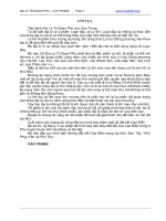
Mentor II
The Intelligent Drive
Overview
DC drives are widely used in applications that
require regeneration, precise speed control, dynamic
performance, and constant torque over wide speed
ranges. The Mentor II delivers the universal DC drive
solution.
Simple stand-alone applications are easily configured
to control motor speed, voltage or current using
standard internal settings. Set-up is convenient using
the drive keypad, CTKP remote keypad, or MentorSoft,
a Windows based drive configuration tool. The Mentor
II has extensive diagnostic and communication abilities
that enhance system reliability. The drive’s standard
yet powerful microprocessor is a versatile system
component that can eliminate the need for a PLC with
integral functions such as thresholds, timers and logic
gates that perform basic control.
The simple addition of the MD29, a 32-bit
application coprocessor card, provides high performance
drive systems with local intelligence for true distributed
control. The MD29 enables users to incorporate custom
or proprietary process control application programs to
their drive. The Mentor II also provides a wide range of
communication protocol options.
Mentor II systems have proven to be extremely
reliable and are ideally suited to web handling, winders,
slitters, extruders, wire drawing, converting lines, and
plastics production. The Mentor II’s integrated design
and highly programmable features make it an ideal
choice for OEMs and System Integrators, as well as
replacement or retrofit drives for End Users.
A
P
P
R
O
V
A
L
I
S
O
9
0
0
2
—Extrusion
—Intelligent
Microprocessor Based Digital DC Drive
5 to 1000 HP, 3 phase, 208 to 660 VAC
Regenerative and non-regenerative models
RS485 serial communications
Extensive fieldbus communication
capabilities
Plug-in 32-bit application coprocessor
card (MD29)
MentorSoft Windows-based
drive configuration tool
Complete Motor Solutions
Digital Drive
Mentor II
99
1-800-893-2321
Feature
Performance Advantage
Accepts wide range of supply voltage (208 to 660 VAC)
Can be applied to worldwide voltages
Non-regen and regen models share the same footprint
Allows for common mechanical design and
mounting
MentorSoft Windows based drive configuration tool
Provides easy programming and diagnostics
of the drive
32-bit application coprocessor card (MD29)
Enables customized applications for distributed
control system architectures
Profibus-DP, Modbus+, Modbus RTU, Interbus-S, DeviceNet,
and CTNet plug-in communication cards
Communicates on user’s preferred network
Built-in RS485 serial communications
Allows for easy programming and control of drive
Extensive and configurable analog and digital I/O
Customizes drive to specific applications
Programmable boolean logic (AND, NAND, OR, NOR)
gates with delay outputs
Assists with general system interface logic needs,
expanding application possibilities
Programmable threshold comparators
Expands application possibilities by providing a pair
of independent numerical comparators with
adjustable hysteresis
Built-in digital lock function for frequency following
Allows accurate master/slave applications
Accepts DC tachometer and encoder feedback
Enables precise speed control
Extensive diagnostics and fault indicators
Used for accurate drive system diagnosis
Ratings: Mentor II
THREE PHASE INPUT
3 to 500 HP (208-230 VAC)
5 to 1000 HP (380-460 VAC)
Special Order (525 / 660 VAC), Models M350(R)–M1850(R) only)
3 - 7 25 20 M25-14M M25R-14M
7.5 - 10 45 38 M45-14M M45R-14M
15 75 55 M75-14M M75R-14M
20 - 35 105 89 M105-14M
M105R-14M
30 155 125 M155-14M
M155R-14M
40 - 50 210 172 M210-14M
M210R-14M
75 350 255 M350-14M
M350R-14M
100 420 338 M420-14M
M350R-14M
125 550 428 M550-14M
M550R-14M
150 700 508 M700-14M
M700R-14M
200 825 675 M825-14M
M825R-14M
250 900 820 M900-14M
M900R-14M
300 - 350 1200 1150 M1200-14M
M1200R-14M
400 - 500 1850 1620 M1850-14M
M1850R-14M
Motor HP
208 / 240 VAC
Output
Current
(A)
(@40°C)
Output
Current
(A)
(@55°C)
Field
Output
Current
Non-Regen
Catalog
Number
Regen
Catalog
Number
➀ For field control, add external field regulator P/N 9500-9035.
8A
Current
Regulated
10A
Fixed
Voltage
➀
20A Fixed
Voltage
➀
5 - 10 25 20 M25-14M M25R-14M
15 - 20 45 38 M45-14M M45R-14M
25 - 30 75 55 M75-14M M75R-14M
40 - 50 105 89 M105-14M M105R-14M
60 - 75 155 125 M155-14M M155R-14M
100 210 172 M210-14M M210R-14M
150 350 255 M350-14M M350R-14M
200 420 338 M420-14M M350R-14M
250 550 428 M550-14M M550R-14M
300 700 508 M700-14M M700R-14M
400 825 675 M825-14M M825R-14M
500 900 820 M900-14M M900R-14M
600 - 700 1200 1150 M1200-14M
M1200R-14M
800 - 1000 1850 1620 M1850-14M
M1850R-14M
Motor HP
380 / 480 VAC
Output
Current
(A)
(@40°C)
Output
Current
(A)
(@55°C)
Field
Output
Current
Non-Regen
Catalog
Number
Regen
Catalog
Number
8A
Current
Regulated
10A
Fixed
Voltage
➀
20A Fixed
Voltage
➀
Order String
M XXX R - 14M
Factory Assigned
Regen (omit for Non-regen)
Output Current
Mentor II Product Family
100
Mentor II
www.emersonct.com
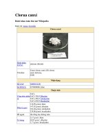
Terminal Diagram: Mentor II
Terminal Description
Pin
#
Function Type/Description Notes
1 +10 VDC Reference Supply 10 mA max
2 -10 VDC
3 Speed Reference Analog Input, 12 bit
±10 VDC, 100k Ohms or
4-20 mA, 100 Ohms
4 Analog Input # 1
5 # 2 Analog Input
6 # 3 Bi-polar, 10 bit + sign ±10 VDC, 100k Ohms
7 # 4
8 Motor Thermistor Analog Input 3k Ohms trip point,
1.8k Ohm reset level
9 DC Tachometer (-) Analog Input
10 DC Tachometer (+) Circuit Common
11 Armature Current Image Analog Output 6.6 VDC @ 150%
current
12 Analog Output # 1
13 # 2 Analog Output ±10 VDC, 5 mA
14 # 3 Bi-polar, 10 bit + sign
15 Digital Output # 1
16 # 2
17 # 3 Digital Output +24 VDC, 100 mA
18 # 4 Open Collector
19 # 5
Pin
#
Function Type/Description Notes
20 0V Common Circuit Common
21 F1 (Run Permit) Digital Input +24 VDC, 10k Ohms
22 F2 (Inch / Jog Reverse)
23 F3 (Inch / Jog Forward)
24 F4 (Run Reverse (latched))
25 F5 (Run Forward (latched))
26 Digital Input F6 Digital Input +24 VDC, 10k Ohms
27 F7
28 F8
29 F9
30 F10
31 Drive Enable Digital Input
30 mSec inhibit delay
32 Reset Digital Input Fault Reset
33 +24 VDC Supply User Supply 200 mA max
34 Form C Status Relay Relay Common
35 (Zero Speed) N. C. Contact
110 VAC, 5A resistive
36 N. O. Contact
37 Form C Status Relay Relay Common
38 (Drive Ready) N. C. Contact
110 VAC, 5A resistive
39 N. O. Contact
40 0V Common Circuit Common
Programmable Analog Programmable Digital All Analog I/O is
scaleable
,
(300mA max.)
Mentor II
101
1-800-893-2321
Specifications: Mentor II
Environment
Ambient Operating 0 to 40°C (32 to 104°F)
Temperature Derate current 1.5% per °C to 55°C (32 to131°F)
Cooling Method Convection and forced convection, model
dependent
Humidity 95% non-condensing at 40°C (104°F)
Storage Temperature -40 to 55°C (-40 to 131°F)
Altitude
0 to 4000m (13,120 ft).
Derate 1% per 100m (328
ft) between 1000m
(3,280 ft) and 4000m (13,120 ft).
Enclosure Chassis (IP00)
AC Supply Requirements
Voltage 208 to 480 VAC -5%, +10%
525/575/660 VAC ±10%
(Optional M350 and above)
Phase 3Ø
Frequency 45 to 62 Hz
Efficiency 98%
Control
Feedback Methods Armature Voltage (resolution .83 volts)
DC Tachometer (resolution 0.1%)
Encoder (resolution .01%)
Field Control Current regulated 8 Amps max
(M210/M210R and smaller)
Voltage regulated .675 or .9 X Line-to-line
voltage (M350/M350R and larger)
Analog Input Resolution 12 bit (Qty 1), 10 bit (Qty 4)
Serial Communications 4-wire RS422 or RS485, optically-isolated
Protocol is ANSI x 3.28-2.5-A4
Baud rate is 4800 or 9600
Protection
AC Line 180 VAC
Undervoltage Trip
MOV Voltage Input transient suppression
Transient Protection
Instantaneous 300% armature current
Overcurrent Trip
Armature Open Circuit Armature circuit is open
Drive Overload Trip Inverse time, 150% for 30 seconds
Phase Loss Trip Loss of input phase
Overtemperature Trip Heatsink exceeds 100°C (212°F)
Motor Thermal Trip Motor over-temp switch or Thermistor
Feedback Loss Loss of motor feedback
Feedback Reversal Tachometer or Encoder wired backwards
Field Loss No field current
Field On Field current during auto-tune
Field Overcurrent Field current greater than field demand
Current Loop Loss Loss of 4-20 mA reference
External Power Supply Short circuit on +24 VDC user power supply
Power Supply Internal power supply out of tolerance
Serial Communications Mode 3 serial comms data loss
Loss
Processor 1 Main control processor fault
Watchdog Trip
Processor 2 Second control processor fault (MD29)
Watchdog Trip
Hardware Fault Hardware malfunction on control board
Memory Fault Stored parameter checksum fault
External Trip User interlock fault (programmed)
Software Fault (A29) MD29 software fault
Approvals & Listings
UL, cUL File #E58592 Vol. 5C Section 1
CE Designed for marking
ISO 9002 Certified Manufacturing Facility
▲
▲
▲
▲
R
E
S
E
T
D
r
i
v
e
R
e
a
d
y
A
l
a
r
m
Z
e
r
o
s
p
e
e
d
R
u
n
f
o
r
w
a
r
d
R
u
n
r
e
v
e
r
s
e
B
r
i
d
g
e
1
B
r
i
d
g
e
2
A
t
s
p
e
e
d
C
u
r
r
e
n
t
l
i
m
i
t
P
A
R
A
M
E
T
E
R
D
A
T
A
P
A
R
A
M
E
T
E
R
I
N
D
E
X
M
O
D
E
Dimensions
Catalog Number Size* (in.) Approx.
H x W x D Weight (lbs.)
M25-14M thru M75-14M 15 x 10 x 6 22
M25R-14M thru M75R-14M 15 x 10 x 6 24
M105-14M thru M210-14M 15 x 10 x 8 31
M105R-14M thru M210R-14M 15 x 10 x 8 33
M350-14M thru M420-14M 16 x 18 x 11 48
M350R-14M thru M420R-14M 16 x 18 x 11 51
M550-14M thru M825-14M 17 x 18 x 11 59
M550R-14M thru M825R-14M 17 x 18 x 11 66
M900-14M thru M1850-14M 41 x 18 x 20 154
M900R-14M thru M1850R-14M 61 x 18 x 20 264
* Approximate, not to be used for construction purposes.
102
Mentor II
www.emersonct.com
S-ramp accel / decel profiling 9729-9001
Digital lock with adjustable ratio control 9729-9002
Spindle orientation 9729-9003
Constant tension, center wind (CTCW) 9729-9004
PID control for load cell tension
or dancer position 9729-9005
Power calculations 9729-9006
Dual Mode Winder 9729-9008
Profibus-DP MD-24 Master / Slave
Interbus-S MDIBS Master / Slave
CTNet* MD-29AN* Peer-to-peer
DeviceNet MD-25 Master / Slave
Modbus RTU* 9729-9000* Master / Slave
Modbus+ 9500-9100 Master / Slave
Mentor II
Options / Software / Accessories
Network Communication Cards
The fieldbus interface cards provide high-speed
communications using the popular networks and
protocol. These networks allow large amounts of data
to be transferred quickly to and from network nodes.
The RS485 channel is optically isolated (CTNet is
transformer isolated) for added protection.
Application Cards (MD29 & MD29AN)
The MD29 (9729-9000) and MD29AN application
cards contain a high-speed microprocessor which
provides a low-cost facility for a system designer to
write application specific programs without needing a
PLC or other stand-alone controller. The add-on cards
fit into a 40-pin header within the Mentor II drive. It
is programmed (via the RS232 port) using our Control
Techniques SyPT (System Programming Toolkit) that
complies with IEC1131-3 Ladder / Function Block or
DPL (Drive Programming Language). In addition to
the application coprocessor, the MD29AN CTNet card
supports peer-to-peer cyclic and broadcast messaging at
rates up to 5Mbaud.
The application cards use dual port RAM to provide
intimate high-speed bi-directional access. They can read
and modify any parameter within the drive, enabling
customized real-time calculations under a multi-tasking
run-time environment. The Intel i960 32-bit RISC
processor and 256K of user program FLASH memory
(equivalent to >2000 lines of ladder logic or basic
instruction code) provide a powerful base for a designer
to accomplish complex algorithms for demanding time-
critical process control.
The optically isolated RS485 channel serves as a
communication port for our CTIU operator interface units.
It is fully configurable, supporting multiple communication
modes including an ANSI 2 or 4-wire protocol at data
rates up to 38.4kbaud. A Modbus protocol with RTU
and ASCII slave modes is also available.
32-bit coprocessor (MD-29) 9729-9000
32-bit coprocessor with CTNet MD29AN-RevD*
*RevD for current product, see page 148 for details.
Network Communications
CTNet
* CTNet and Modbus RTU cards contain full coprocessor ability.
Refer to the Application Cards (MD29 and MD29AN) for more information.
Communication Interface Module System
Protocol Catalog Number Configuration
* Contact Control Techniques for detailed information.
Pre-configured Application Programs* Catalog Number
MD-29
MD-29AN
Mentor II
103
1-800-893-2321
Mentor II
PC to Drive Accessories
Drive Configuration Tool (MentorSoft)
MentorSoft is a complimentary Windows based drive
configuration tool designed to enable the complete
control and display of all parameters within a Mentor II.
Functions within MentorSoft allow data to be uploaded,
viewed and saved or retrieved from disk, modified and
printed. It can be used off-line in the office or on-line
on the plant floor. MentorSoft communicates with
the Mentor II via the computer’s serial port to the
drive’s RS485 port using a communications cable
(CTD-PC-485-XXX). (XXX=ft.)
Some of its many capabilities include:
Commissioning screen – displays wiring and
control logic
Compare functions – compares current drive
configuration with previously stored versions
User screen – customized by the user with up
to 15 key parameters
Built-in reference manuals and search functions
– provide extensive “Help” files for both the
drive and the software
For more information, refer to the Accessories
Section on page 138.
Operator Interfaces
Universal Keypad (CTKP)
The CTKP Universal Keypad is an
ideal maintenance tool for use with
CT’s digital drives (SE, Unidrive,
Mentor II, Quantum III) and option
modules (UD7X, MD series). Five
navigation keys and plain text
parameter descriptions make the
CTKP easy to use for viewing and
modifying drive data. The keypad is designed for hand-
held or panel mounting. The IP65 rating, screw-down
terminals and stress relief for cable connections assure a
rugged and robust design.
For more information, refer to the Accessories
Section on page 154.
Operator Interface Unit (CTIU)
The CTIU operator interface units incorporate a
back-lit LCD display and five easy-to-use navigation
keys. Using the intuitive “WYSIWIG” page editor, they
can be programmed to display a variety of menus,
submenus, alarms, fault conditions and other critical
information. The CTIUs support a range of capabilities
including multiple font sizes, real time trends and
graphs, scheduling and background programs. They
communicate via 2 or 4-wire RS485 and to simplify
installation, CTIUs are rated NEMA 4/12 and require no
screw mounting holes.
For more information, refer to the Accessories
Section on pages 152-53.
104
Mentor II
www.emersonct.com
9500-9035 20 50 220 / 380 / 440 198 / 342 / 396
60 240 / 480 216 / 432
9500-9032 50 50 220 / 380 / 440 198 / 342 / 396
60 240 / 480 216 / 432
9500-9033 90 50 220 / 380 / 440 198 / 342 / 396
60 240 / 480 216 / 432
1 Analog Input (12 bit)
±10 VDC, 100k Ohms or
4-20 mA, 100 Ohms
4 Analog Input (10 bit) ±10 VDC, 100k Ohms
3 Analog Output (10 bit) ±10 VDC, 5 mA
8 Digital Input +24 VDC, 10k Ohms
8 Digital Output +24 VDC, 100 mA
(200 mA total for all outputs)
Mentor II
Remote I/O (I/O Box)
The I/O Box expands the I/O capabilities of the
Mentor II and Quantum III drives. The I/O Box is
connected to the drive through the MD29 / AN
application card using an optically isolated RS485
serial link.
Specifications
Voltage 110 to 240 VAC ±10%
Frequency 48 to 62 Hz
Phase 1Ø
RS485 Interface Supports binary protocol at data rates
up to 38.4kbaud for connection to a
single drive.
Field Regulators (FXM Family)
The FXM family
of field regulators is
designed to control
the field current of
DC motors up to 90
amps. When used
in conjunction with
either the Mentor II or
Quantum III variable
speed DC drives, the field regulator is controlled directly
via the drive parameters. This allows full customization
of the field control for any application. The FXMs can
also be used as stand-alone units when retrofitting
existing applications.
The field regulators are single phase, controlled
thyristor rectifier bridges with a control logic PC board.
The bridge can be configured by jumpers to operate
in half (single quadrant) or full (two quadrant) control
mode.
The FXMs may be independently controlled by an
external reference, or set for automatic field weakening
(constant horsepower) or constant field current. Field
economy control via contact or logic input and a field
loss relay for protection are provided for stand-alone
operation. The unit also has a bar graph display (10%
increments of the selected range) for field current
magnitude.
* Maximum output voltage equals 90% of input RMS line voltage.
Field current is the controlled variable.
Qty Type / Description Notes
Catalog Current Frequency Input Voltage Output Voltage*
Number (A) (Hz) (VAC) (VDC)
Mentor II
105
1-800-893-2321
M25 – M210 M25-210-SP 1 – MDA1 Control board
(non-regen 1 – MDA2B Interface board
and regen) 6 – Power board fuses
M350 – M825 M350-825-SP 1 – MDA1 Control board
(non-regen 1 – MDA2B Interface board
and regen) 6 – Fuses for MDA5 Filter board
6 – Fuses for MDA6 Power board
M900 – M1850 M900-1850-SP 1 – MDA1 Control board
(non-regen)
1 – MDA2B Interface board
M900R – M1850R M900R-1850R-SP 1 – SCR heatsink assembly
(regen)
6 – 6A fuses for MDA6 board
2 – 2A fuses for SD1 board
2 – 30A fuses for SD1 board
Mentor II
Critical Components
Drive Frame Kit Cat. No. Description
Size
Minimize Your Machine Downtime Delays
All too often, spare parts are over looked which results
in a panic search, no less the possibility of costly Next
Day shipping expenses. Having these items on hand can
reduce the associated stress of machine downtime. To
facilitate this effort, Control Techniques has assembled
several levels of Critical Component kits to fit within
your maintenance budget constraints. These pre-
assembled kits represent a significant savings over
purchasing the same items separately.
Warranty
Extended Warranty
An industry-leading two-year warranty is standard
for Mentor II drives. An extended warranty is available
that increases the warranty period to five years.
M25 M25WE
M45 M45WE
M75 M75WE
M105 M105WE
M155 M155WE
M210 M210WE
M350 M350WE
M420 M420WE
M550 M550WE
M700 M700WE
M825 M825WE
M900 M900WE
M1200 M1200WE
M1850 M1850WE
Mentor II Model Catalog Number