Tài liệu DSP applications using C and the TMS320C6X DSK (P1) ppt
Bạn đang xem bản rút gọn của tài liệu. Xem và tải ngay bản đầy đủ của tài liệu tại đây (826.04 KB, 32 trang )
1
DSP Development System
1
•
Testing the software and hardware tools with Code Composer Studio
•
Use of the TMS320C6711 DSK
•
Programming examples to test the tools
Chapter 1 introduces several tools available for digital signal processing (DSP).
These tools include the popular Code Composer Studio (CCS), which provides an
integrated development environment (IDE); the DSP starter kit (DSK) with the
TMS320C6711 floating-point processor onboard and complete support for input
and output. Three examples are included to test both the software and hardware
tools included with the DSK.
1.1 INTRODUCTION
Digital signal processors such as the TMS320C6x (C6x) family of processors are like
fast special-purpose microprocessors with a specialized type of architecture and
instruction set appropriate for signal processing. The C6x notation is used to desig-
nate a member of Texas Instruments’ (TI) TMS320C6000 family of digital signal
processors. The architecture of the C6x digital signal processor is very well suited
for numerically intensive calculations. Based on a very-long-instruction-word
(VLIW) architecture, the C6x is considered to be TI’s most powerful processor.
Digital signal processors are used for a wide range of applications, from com-
munications and controls to speech and image processing. They are found in cellu-
lar phones, fax/modems, disk drives, radio, and so on. These processors have become
the product of choice for a number of consumer applications, since they have
become very cost-effective. They can handle different tasks, since they can be
DSP Applications Using C and the TMS320C6x DSK. Rulph Chassaing
Copyright © 2002 John Wiley & Sons, Inc.
ISBNs: 0-471-20754-3 (Hardback); 0-471-22112-0 (Electronic)
reprogrammed readily for a different application. DSP techniques have been very
successful because of the development of low-cost software and hardware support.
For example, modems and speech recognition can be less expensive using DSP
techniques.
DSP processors are concerned primarily with real-time signal processing. Real-
time processing means that the processing must keep pace with some external event;
whereas non-real-time processing has no such timing constraint. The external event
to keep pace with is usually the analog input. While analog-based systems with dis-
crete electronic components such as resistors can be more sensitive to temperature
changes, DSP-based systems are less affected by environmental conditions such as
temperature. DSP processors enjoy the advantages of microprocessors. They are
easy to use, flexible, and economical.
A number of books and articles have been published that address the importance
of digital signal processors for a number of applications [1–20]. Various tech-
nologies have been used for real-time processing, from fiber optics for very high fre-
quency to DSP processors very suitable for the audio-frequency range. Common
applications using these processors have been for frequencies from 0 to 20kHz.
Speech can be sampled at 8kHz (how quickly samples are acquired), which implies
that each value sampled is acquired at a rate of 1/(8kHz) or 0.125ms. A commonly
used sample rate of a compact disk is 44.1kHz.A/D-based boards in the megahertz
sampling rate range are currently available.
The basic system consists of an analog-to-digital converter (ADC) to capture
an input signal. The resulting digital representation of the captured signal is then
processed by a digital signal processor such as the C6x and then output through a
digital-to-analog converter (DAC).Also included within the basic system is a special
input filter for antialiasing to eliminate erroneous signals, and an output filter to
smooth or reconstruct the processed output signal.
1.2 DSK SUPPORT TOOLS
Most of the work presented in this book involves the design of a program to imple-
ment a DSP application. To perform the experiments, the following tools are used:
1. TI’s DSP starter kit (DSK). The DSK package includes:
(a) Code Composer Studio (CCS), which provides the necessary software
support tools. CCS provides an integrated development environment
(IDE), bringing together the C compiler, assembler, linker, debugger, and
so on.
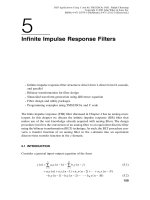
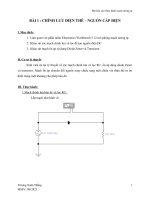
(b) A board, shown in Figure 1.1a, that contains the TMS320C6711 (C6711)
floating-point digital signal processor as well as a 16-bit codec for input
and output (I/O) support.
(c) A parallel cable (DB25) that connects the DSK board to a PC.
(d) A power supply for the DSK board.
2
DSP Development System
2. An IBM-compatible PC. The DSK board connects to the parallel port of the
PC through the DB25 cable included with the DSK package.
3. An oscilloscope, signal generator, and speakers. A signal/spectrum analyzer is
optional. Shareware utilities are available that utilize the PC and a sound card
to create a virtual instrument such as an oscilloscope, a function generator, or
a spectrum analyzer.
DSK Support Tools 3
(a)
(b)
FIGURE 1.1. TMS320C6711-based DSK board: (a) board; (b) diagram (Courtesy of Texas
Instruments).
All the files/programs listed and discussed in this book (except the student project
files in Chapter 9) are included on the accompanying disk. Most of the examples
can also run on the fixed-point C6211-based DSK (which has been discontinued).
A list of all the examples is given on pages xv–xviii.
1.2.1 DSK Board
The DSK package is powerful, yet relatively inexpensive ($295), with the necessary
hardware and software support tools for real-time signal processing [21–33]. It is a
complete DSP system. The DSK board, with an approximate dimension of 5 ¥ 8
inches, includes the C6711 floating-point digital signal processor [22] and a 16-bit
codec AD535 for input and output.
The onboard codec AD535 [34] uses a sigma–delta technology that provides
analog-to-digital conversion (ADC) and digital-to-analog conversion (DAC). A
4-MHz clock onboard the DSK connects to this codec to provide a fixed sampling
rate of 8kHz.
A daughter card expansion is also provided on the DSK board. We will illustrate
input and output by plugging an audio daughter card based on the PCM3003 stereo
codec (not included with the DSK package) into an 80-pin connector on the DSK
board.The audio daughter card is available from Texas Instruments and is described
in Appendix F. The PCM3003 codec has variable sample rates up to 72 kHz and can
be useful for applications requiring higher sampling rates and two accessible input
and output channels.
The DSK board includes 16 MB (megabytes) of synchronous dynamic RAM
(SDRAM) and 128kB (kilobytes) of flash ROM. Two connectors on the board
provide input and output and are labeled IN (J7) and OUT (J6), respectively.Three
of the four user dip switches on the DSK board can be read from a program (a
project example on voice scrambling makes use of these switches). The onboard
clock is 150MHz. Also onboard the DSK are voltage regulators that provide 1.8 V
for the C6711 core and 3.3V for its memory and peripherals.
1.2.2 TMS320C6711 Digital Signal Processor
The TMS320C6711 (C6711) is based on the very-long-instruction-word (VLIW)
architecture, which is very well suited for numerically intensive algorithms. The
internal program memory is structured so that a total of eight instructions can be
fetched every cycle. For example, with a clock rate of 150 MHz, the C6711 is capable
of fetching eight 32-bit instructions every 1/(150MHz) or 6.66ns.
Features of the C6711 include 72 kB of internal memory, eight functional or exe-
cution units composed of six ALUs and two multiplier units, a 32-bit address bus to
address 4GB (gigabytes), and two sets of 32-bit general-purpose registers.
The C67xx (such as the C6701 and C6711) belong to the family of the C6x
floating-point processors; whereas the C62xx and C64xx belong to the family of
the C6x fixed-point processors. The C6711 is capable of both fixed- and floating-
4
DSP Development System
point processing. The architecture and instruction set of the C6711 are discussed in
Chapter 3.
1.3 CODE COMPOSER STUDIO
The Code Composer Studio (CCS) provides an integrated development environ-
ment (IDE) to incorporate the software tools. CCS includes tools for code genera-
tion, such as a C compiler, an assembler, and a linker. It has graphical capabilities
and supports real-time debugging. It provides an easy-to-use software tool to build
and debug programs.
The C compiler compiles a C source program with extension .c to produce an
assembly source file with extension.asm. The assembler assembles an .asm source
file to produce a machine language object file with extension.obj. The linker com-
bines object files and object libraries as input to produce an executable file with
extension .out. This executable file represents a linked common object file format
(COFF), popular in Unix-based systems and adopted by several makers of digital
signal processors [21]. This executable file can be loaded and run directly on the
C6711 processor.
To create an application project, one can “add” the appropriate files to the
project. Compiler/linker options can readily be specified. A number of debugging
features are available, including setting breakpoints and watching variables, viewing
memory, registers, and mixed C and assembly code, graphing results, and monitor-
ing execution time. One can step through a program in different ways (step into, or
over, or out).
Real-time analysis can be performed using real-time data exchange (RTDX)
associated with DSP/BIOS (Appendix G). RTDX allows for data exchange between
the host and the target and analysis in real time without stopping the target. Key
statistics and performance can be monitored in real time. Through the Joint Team
Action Group (JTAG), communication with on-chip emulation support occurs to
control and monitor program execution. The C6711 DSK board includes a JTAG
emulator interface.
1.3.1 CCS Installation and Support
Use the parallel (printer) cable DB25 to connect the DSK board (J2) to the paral-
lel port on the PC, such as LPT1 or LPT2. Use the 5-V adapter included with the
DSK package to connect to the power connector J4, to turn on the DSK. Install
CCS with the CD-ROM included with the DSK, preferably using the c:\ti
structure (as default).
The CCS icon should be on the desktop as “CCS 2 [’C 6000]” and is used to launch
CCS.The code generation tools (C compiler, assembler, linker) Version 4.1 are used.
On power, the three LEDs located near the four user dip switches should count
from 1 to 7 (binary).
Code Composer Studio 5
CCS provides useful documentations included with the DSK package on the
following (see the Help icon):
1. Code generation tools (compiler, assembler, linker, etc.)
2. Tutorials on CCS, compiler, RTDX, advanced DSP/BIOS
3. DSP instructions and registers
4. Tools on RTDX, DSP/BIOS, and so on.
An extensive amount of support material (pdf files) is included with CCS (see
Refs. 22 to 34). There are also a few examples included with CCS, such as a confi-
dence test example for the DSK, an audio example, and an example associated with
the onboard flash.
CCS Version 2 was used to build and test the examples included in this book. A
number of files included in the following subfolders/directories within c:\ti can
be very useful:
1. docs: contains documentation and manuals.
2. myprojects: supplied for your projects. All the programs and projects dis-
cussed in this book can be placed within this subdirectory.
3. c6000\cgtools: contains code generation tools.
4. bin: contains many utilities.
5. c6000\examples: contains examples included with CCS.
6. c6000\RTDX: contains support files for real-time data transfer.
7. c6000\bios: contains support files for DSP/BIOS.
1.3.2 Useful Types of Files
You will be working with a number of files with different extensions. They include:
1. file.pjt: to create and build a project named file.
2. file.c: C source program.
3. file.asm: assembly source program created by the user, by the C compiler,
or by the linear optimizer.
4. file.sa: linear assembly source program. The linear optimizer uses file.sa
as input to produce an assembly program file.asm.
5. file.h: header support file.
6. file.lib: library file, such as the run-time support library file
rts6701.lib.
7. file.cmd: linker command file that maps sections to memory.
8. file.obj: object file created by the assembler.
6
DSP Development System
9. file.out: executable file created by the linker to be loaded and run on the
processor.
1.4 PROGRAMMING EXAMPLES TO TEST THE DSK TOOLS
Three programming examples are introduced to illustrate some of the features of
CCS and the DSK board. The primary focus is to become familiar with both the
software and hardware tools. It is strongly suggested that you complete these three
examples before proceeding to subsequent chapters.
1.4.1 Quick Test of DSK
Launch CCS from the icon on the desktop. Press GEL Æ Check DSK Æ Quick
Test. The Quick Test can be used for confirmation of correct operation and instal-
lation. The following message is then displayed:
Switches: 7
Revision: 2
Target is OK
This assumes that the first three switches, USER_SW1, USER_SW2, and
USER_SW3, are all in the up (ON) position. Change the switches to (1 1 0 x)
2
so that
the first two switches are up (press the third switch down). The fourth switch is not
used.
Repeat the procedure to select GEL Æ Check DSK Æ Quick Test and verify
that the value of the switches is now 3 (with the display “Switches: 3”). You can set
the value of the first three user switches from 0 to 7. Within your program you can
then direct the execution of your code based on these eight values. Note that the
Quick Test cycles the LEDs three times.
A confidence test program example is included with the DSK to test and verify
proper operation of the major components of the DSK, such as interrupts, LEDs,
SDRAM, DMA, serial ports, and timers.
Alternative Quick Test of DSK
1. Open/launch CCS from the icon on the desktop. Select File Æ Load Program.
Access the accompanying disk. Click on the folder sine8_intr to Open
(load) the file sine8_intr.out. This loads the executable file
sine8_intr.out into the C6711 processor.
2. Select Debug Æ Run. Connect the OUT (connector J6) on the DSK board to
a speaker or to an oscilloscope and verify the generation of a 1-kHz tone. The
IN/OUT connectors (J7/J6) on the DSK board use a 3.5-mm jack audio cable.
Programming Examples to Test the DSK Tools 7
The folder sine8_intr contains the necessary files to implement Example 1.1,
which introduces some features of the tools.
1.4.2 Support Files
Create a new folder within your PC hard drive and name it sine8_intr. It is rec-
ommended that you place this folder in c:\ti\myprojects (it is assumed that
you have installed CCS in c:\ti). Some of the same support files that are used in
many examples in this book are included on the accompanying disk in the folder
Support. For now, don’t worry too much about the content or functions of these
files. Additional support files are included in the CCS CD with the DSK package.
Copy the following support files from the folder Support (on the accompanying
disk) into the folder sine8_intr that you created in your hard drive:
1. C6xdsk.cmd: sample linker command file.
2. C6xdsk.h: header file that defines addresses of external memory interface,
the serial ports, etc. (TI support file included with CCS).
3. C6xinterrupts.h: contains init functions for interrupt (TI support file
included with the DSK).
4. C6xdskinit.h: header file with the function prototypes.
5. C6xdskinit.c: contains several functions used for the example
codec_poll included with CCS. It includes functions to initialize the DSK,
the codec, the serial ports, and for input/output.
6. Vectors_11.asm: version of vectors.asm included with CCS, but modi-
fied to handle interrupts. Twelve interrupts, INT4 through INT15, are avail-
able, and INT11 is selected within this vector file.
Also copy the C source file sine8_intr.c and the GEL file amplitude.gel from
the disk (sine8_intr folder) into the folder sine8_intr on your hard drive.
Note: If you are using a C6211 DSK (which has been discontinued), change
XINT0 to XINT1 within the function comm_intr in the file C6xdskinit.c. This
is due to a silicon bug associated with the C6211.
1.4.3 Examples
Example 1.1: Sine Generation with Eight Points (sine8_intr)
This example generates a sinusoid using a table-lookup method. More important, it
illustrates some features of CCS for editing, building a project, accessing the code
generation tools, and running a program on the C6711 processor. The C source
program sine8_intr.c shown in Figure 1.2 implements the sine generation.
8
DSP Development System
Program Consideration
Although the focus is to illustrate some of the tools, it is useful to understand the
program sine8_intr.c. A table or buffer sin_table is created and filled with
eight points representing sin(t), where t = 0, 45, 90, 135, 180, 225, 270, and 315 degrees
(scaled by 1000). Within the function main, another function comm_intr is called
that is located in the communication support file c6xdskinit.c. It initializes the
DSK, the AD535 codec onboard the DSK, and the two multichannel buffered serial
ports (McBSPs) on the C6711 processor.
The statement while (1) within the function main creates an infinite loop
to wait for an interrupt to occur. On interrupt, execution proceeds to the inter-
rupt service routine (ISR) c_int11. This ISR address is specified in the file
vectors_11.asm with a branch instruction to this address, using interrupt INT11.
Interrupts are discussed in more detail in Chapter 3.
Within the ISR, the function output_sample, located in the communication
support file C6xdskinit.c, is called to output the first data value in the buffer or
table sin_table[0] = 0. The loop index is incremented until the end of the
table is reached, after which case it is reinitialized to zero. Execution returns from
ISR to the while(1) infinite loop to wait for the next interrupt to occur.
An interrupt occurs every sample period T = 1/F
s
= 1/8000 = 0.125ms. Every
sample period 0.125ms, an interrupt occurs, ISR is accessed, and a subsequent data
value in sin_table (scaled by amplitude = 10) is sent for output. Within one
period, eight data values (0.125 ms apart) are output to generate a sinusoidal signal.
Programming Examples to Test the DSK Tools 9
//sine8_intr.c Sine generation using 8 points, f=Fs/(# of points)
//Comm routines and support files included in C6xdskinit.c
short loop = 0;
short sin_table[8] = {0,707,1000,707,0,-707,-1000,-707}; //sine values
short amplitude = 10; //gain factor
interrupt void c_int11() //interrupt service routine
{
output_sample(sin_table[loop]*amplitude); //output each sine value
if (loop < 7) ++loop; //increment index loop
else loop = 0; //reinit index @ end of buffer
return; //return from interrupt
}
void main()
{
comm_intr(); //init DSK, codec, McBSP
while(1); //infinite loop
}
FIGURE 1.2. Sine generation program using eight points (sine8_intr.c).
The period of the output signal is T = 8(0.125ms) = 1 ms, corresponding to a fre-
quency of f = 1/T = 1kHz.
Create Project
In this section we illustrate how to create a project, adding the necessary files for
building the project sine8_intr. Access CCS (from the desktop).
1. To create the project file sine8_intr.pjt. Select Project Æ New. Type
sine8_intr for project name as shown in Figure 1.3a. This project file is
saved in sine8_intr (the folder you created in c:\ti\myprojects). The
.pjt file stores project information on build options, source filenames, and
dependencies.
2. To add files to project. Select Project Æ Add Files to Project. Look in
sine8_intr, Files of type C Source Files. Open the two C source files
C6xdskinit.c and sine8_intr.c. Open (to add to project) one file at a
time; or place the cursor to one of these files, then to the other while holding
the Shift key, and press Open. Click on the “+” symbol on the left of the Project
Files window within CCS to expand and verify that the two C source files have
been added to the project.
3. Select Project Æ Add Files to Project. Look in sine8_intr. Use the pull-
down menu for Files of type: and select ASM Source Files. Double-click on
the assembly source file vectors_11.asm to open/add it to the project.
4. Repeat step 3 but select Files of type: Linker Command File, and add the
linker command file C6xdsk.cmd to the project.
5. Repeat step 3, but select Files of type: Object and Library Files. Look in
c:\ti\c6000\cgtools\lib and select the run-time support library file
rts6701.lib (which supports the C67x/C62x architecture) to add to the
project. This assumes that you used the default destination of c:\ti when
you installed CCS.
6. Verify that the linker command (.cmd) file, the project (.pjt) file, the library
(.lib) file, the two C source (.c) files, and the assembly (.asm) file have
been added to the project. The GEL file dsk6211_6711.gel is added auto-
matically when you create the project. It initializes the DSK.
7. Note that there are no “include” files yet. Select Project Æ Scan All Depen-
dencies. This adds/includes the header files: C6xdsk.h, C6xdskinit.h,
C6xinterrupts.h, and C6x.h. The first three header files were copied
(transferred) from the accompanying disk, and C6x.h is included with CCS.
The Files window in CCS should look as in Figure 1.3b. Any of the files (except
the library file) from CCS’s Files window can be displayed by clicking on it. You
should not add header or include files to the project. They are added to the project
automatically when you select: Scan All Dependencies.
10
DSP Development System
It is also possible to add files to a project simply by “dragging” the file (from a
different window) and dropping it into the CCS Project window.
Code Generation and Options
Various options are associated with the code generation tools: C compiler and linker
to build a project.
Programming Examples to Test the DSK Tools 11
(a)
(b)
FIGURE 1.3. CCS Project View window for sine8_intr:(a) creating project; (b) pro-
ject files.
Compiler Option. Select Project Æ Build Options. Figure 1.4a shows CCS window
Build Options for the compiler. Select the following for the compiler option: (a)
Basic (for Category), (b) Default (for Target Version), (c) Full Symbolic Debug (for
Generate Debug Info), (d) Speed most critical (for Opt Speed vs. size), (e) None
(for Opt Level and Program Level Opt). The resulting compiler option is
–gks
The –k option is to keep the assembly source file sine8_intr.asm. The –g option
is to enable symbolic debugging information, useful during the debugging process,
and used in conjunction with the option –s to interlist the C source file with the
assembly source file sine8_intr.asm. generated. The –g option disables many
code optimizations to facilitate the debugging process.
Selecting “Default” for Target Version invokes a fixed-point implementation.
(If you have a C6211 DSK, you must use this option.) The C6711-based DSK can
use either fixed- or floating-point processing. Most examples implemented in this
book can run using fixed-point processing. You will need to select C671x to invoke
a floating-point implementation for the examples in Chapter 6 and 7.
If No Debug is selected (for Generate Debug Info), and –o3:File is selected
(for Opt Level), the Compiler option is automatically changed to
–ks –o3
The –o3 option invokes the highest level of optimization for performance or exe-
cution speed. For now, speed is not critical (neither is debugging). Use the compiler
option –gks (you can type it directly in the compiler command window). Initially,
one would not optimize for speed but to facilitate debugging. There are a number
of compiler options described in Ref. 26.
Linker Option. Click on Linker (from CCS Build Options) and select Absolute
Executable (for Output Module), sine8_intr.out (for Output Filename), and
Run-time Autoinitialization (for Autoinit Model). The output filename defaults to
the name of the .pjt filename. The linker option should be displayed as in Figure
1.4(b)
–g –c –o “sine8_intr.out” –x
The –c option is used to initialize variables at run time, and the –o option is to
name the linked executable output file sine8_intr.out. Press OK.
Note that you can choose to store the executable file within a subfolder “Debug,”
especially during the debugging stage of a project.
Again, these various options can be typed directly within the appropriate
command windows.
12
DSP Development System
Programming Examples to Test the DSK Tools 13
(b)
FIGURE 1.4. CCS Build options: (a) compiler; (b) linker.
(a)
Building and Running the Project
The project sine8_intr can now be built and run.
1. Build this project as sine8_intr. Select Project Æ Rebuild All. Or press
the toolbar with the three down arrows. This compiles and assembles all the
C files using cl6x and assembles the assembly file vectors_11.asm using
asm6x. The resulting object files are then linked with the run-time library
support file rts6701.lib using lnk6x. This creates an executable file
sine8_intr.out that can be loaded into the C6711 processor and run. Note
that the commands for compiling, assembling, and linking are performed with
the Build option. A log file cc_build_Debug.log is created that shows the
files that are compiled and assembled, along with the compiler options
selected. It also lists the support functions that are used. Figure 1.5 shows
several windows within CCS for the project sine8_intr.
2. Select File Æ Load Program in order to load sine_intr.out by clicking on
it (CCS includes an option to load the program automatically after a build).
It should be in the project sine8_intr folder. Select Debug Æ Run, or use
the toolbar with the “running man.” Connect a speaker to the OUT con-
nector (J6) on the DSK. You should hear a tone.
14
DSP Development System
FIGURE 1.5. CCS windows for project sine8_intr.
The sampling rate F
s
of the codec is fixed at 8kHz. The frequency gener-
ated is f = F
s
/(number of points) = 8 kHz/8 = 1kHz. Connect the output of the
DSK to an oscilloscope to verify a 1-kHz sinusoidal signal with an amplitude
of approximately 0.85V p-p (peak to peak).
Monitoring the Watch Window
Verify that the processor is still running. Note the indicator “DSP RUNNING” at
the bottom left of CCS. The Watch window allows you to change the value of a
parameter or to monitor a variable:
1. Select View Æ Quick Watch window, which should be displayed on the lower-
section of CCS.Type amplitude, then click on “Add to Watch.”The amplitude
value of 10 set in the program in Figure 1.2 should appear in the Watch window.
2. Change amplitude from 10 to 30.
3. Verify that the volume of the generated tone has increased (note that the
processor was still running). The amplitude of the sine wave has increased
from approximately 0.85V p-p to approximately 2.6V p-p.
4. Change amplitude to 33 (as in step 2). Verify a higher-pitch tone, which
implies that the frequency of the sine wave has changed just by changing its
amplitude. This is not so. You have overflowed the capacity of the 16-bit codec
AD535. Since the values in the table are scaled by 33, the range of these values
is now between + and -33,000. The range of output values is limited from -2
15
to (2
15
- 1), or from -32,768 to +32,767, due to the AD535 codec. Don’t attempt
to send more than 16 bits’ worth of data to the codec.The onboard codec uses
a 2’s-complement format.
Correcting Program Errors
1. Delete the semicolon in the statement
short amplitude = 10;
If the C source file sine8_intr is not displayed, double-click on it (from the
Files window).
2. Select Debug Æ Build to perform an incremental build or use the toolbar with
the two (not three) arrows. The incremental build is chosen so that only the
C source file sine8_intr.c is compiled. With the Rebuild option (toolbar
with three arrows), files compiled and/or assembled previously would again
go through this unnecessary process.
3. An error message, highlighted in red, stating that a “;” is expected, should
appear in the Build window of CCS (lower left). You may need to scroll-up
the Build window for a better display of this error message. Double-click on
the highlighted error message line. This should bring the cursor to the section
of code where the error occurs. Make the appropriate correction, Build again,
Load, and Run the program to verify your previous results.
Programming Examples to Test the DSK Tools 15
Applying the Slider Gel File
The General Extension Language (GEL) is an interpretive language similar to (a
subset of) C. It allows you to change a variable such as amplitude, sliding through
different values while the processor is running. All variables must first be defined
in your program.
1. Select File Æ Load GEL and open the file amplitude.gel, that you copied
(from the accompanying disk) into the folder sine8_intr. Double-click on
the file amplitude.gel to view it within CCS. It should be displayed in the
Files window. This file is shown in Figure 1.6. By creating the slider function
amplitude shown in Figure 1.6, you can start with an initial value of 10 (first
value) for the variable amplitude that is set in the C program, up to a value
of 35 (second value), incremented by 5 (third value).
2. Select GEL Æ Sine Amplitude Æ Amplitude. This should bring out the
Slider window shown in Figure 1.7, with the minimum value of 10 set for
amplitude.
3. Press the up-arrow key to increase the amplitude value from 10 to 15, as dis-
played in the Slider window. Verify that the volume of the sine wave gener-
ated has increased. Press the up-arrow key again to continue increasing the
slider, incrementing by 5 up to 30. The amplitude of the sine wave should be
about 2.6V p-p with an amplitude value set at 30. Now use the mouse to click
on the Slider window and slowly increase the slider position to 31, then 32,
and verify that the frequency generated is still 1kHz. Increase the slider to 33
and verify that you are no longer generating a 1-kHz sine wave (rather a signal
with two tones: 1 and 3 kHz). The table values, scaled by amplitude, are now
between + and -33,000 (beyond the acceptable range by the codec).
Two sliders can readily be used, one to change the amplitude and the other to
change the frequency. A different frequency can be generated by changing the loop
index within the C program (e.g., stepping through every two points in the table;
see Example 2.4). When you exit CCS after you build a project, all changes made
to the project can be saved. You can later return to the project with the status as
you left it before.
16
DSP Development System
/*Amplitude.gel Create slider and vary amplitude of sinewave*/
menuitem “Sine Amplitude”
slider Amplitude(10,35,5,1,amplitudeparameter) /*start at 10,up to 35*/
{
amplitude = amplitudeparameter; /*vary amplit of sine*/
}
FIGURE 1.6. GEL file to “slide” through different amplitude values in the sine generation
program (amplitude.gel).
Example 1.2: Generation of Sinusoid and Plotting with CCS (sine8_buf)
This example generates a sinusoid with eight points, as in Example 1.1. More impor-
tant, it illustrates CCS capabilities for plotting in both time and frequency domains.
The program sine8_buf.c (Figure 1.8), implements this project. This program
creates a buffer to store the output data in memory.
Create this project as sine8_buf.pjt, add the necessary files to the project as
in Example 1.1 (use sine8_buf.c in lieu of sine8_intr.c). Note that the
necessary header support files are added to the project by selecting Project Æ
Scanning All Dependencies. All of the support files for this project are in the
folder sine8_buf (on disk).
Build this project as sine8_buf. Load and run the executable file
sine8_buf.out and verify that a 1-kHz sinusoid is generated with the output
connected to a speaker or a scope (as in Example 1.1).
Plotting with CCS
The output buffer is being updated continuously every 256 points (you can readily
change the buffer size). Use CCS to plot the current output data stored in the buffer
out_buffer.
1. Select View Æ Graph Æ Time/Frequency.
2. Change the Graph Property Dialog so that the options in Figure 1.9a are
selected for a time-domain plot (use the pull-down menu when appropriate).
The starting address of the output buffer is out_buffer. The other options
can be left as default. Figure 1.10 shows a time-domain plot of the sinusoidal
signal.
Programming Examples to Test the DSK Tools 17
FIGURE 1.7. CCS slider window for varying the amplitude of a sine wave.
18 DSP Development System
//sine8_buf Sine generation. Output buffer plotted within CCS
//Comm routines and support files included in C6xdskinit.c
short loop = 0;
short sine_table[8] = {0,707,1000,707,0,-707,-1000,-707}; //sine values
short out_buffer[256]; //output buffer
const short BUFFERLENGTH = 256; //size of output buffer
short i = 0; //for buffer count
interrupt void c_int11() //interrupt service routine
{
output_sample(sine_table[loop]); //output each sine value
out_buffer[i] = sine_table[loop]; //output to buffer
i++; //increment buffer count
if (i == BUFFERLENGTH) i = 0; //if bottom reinit buffer count
if (loop < 7) ++loop; //increment index loop
else loop = 0; //if end of buffer,reinit index
return;
}
void main()
{
comm_intr(); //init DSK, codec, McBSP
while(1); //infinite loop
}
(a)
(b)
FIGURE 1.9. CCS Graph Property Dialog for sine8_buf:(a) for time-domain plot;
(b) for frequency-domain plot.
FIGURE 1.8. Sine generation with output stored in memory also (sine8_buf.c).
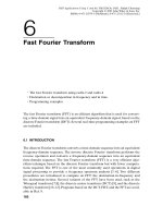
3. Figure 1.9b shows CCS’s Graph Property Display for a frequency-domain plot.
Choose an FFT order so that 2
order
is the frame size. Press OK and verify that
the FFT magnitude plot is as shown in Figure 1.10. The spike at 1000 Hz
represents the frequency of the sinusoid generated.
Note: To change the screen size, right-click on the Build window and deselect
Allow Docking. You can then obtain many different windows within CCS.
Example 1.3: Dot Product of Two Arrays (dotp4)
Operations such as addition/subtraction and multiplication are the key operations
in a digital signal processor.A very important operation is the multiply/accumulate,
which is useful in a number of applications requiring digital filtering, correlation,
and spectrum analysis. Since the multiplication operation is executed so commonly
and is so essential for most digital signal processing algorithms, it is important that
it executes in a single cycle. With the C6x we can actually perform two multiply/
accumulate operations within a single cycle.
This example illustrates additional features of CCS, such as single-stepping and
profiling for benchmark. The focus here is to become still more familiar with the
Programming Examples to Test the DSK Tools 19
1.3e+5
1.2e+5
1.0e+5
9.0e+4
7.7e+4
6.4e+4
5.1e+4
3.8e+4
2.6e+4
1.3e+4
0
0
1000 2000 3000
FIGURE 1.10. CCS windows with both time- and frequency-domain plots of a 1-kHz sine
wave.
tools. We invoke the C compiler optimization to see how performance or execution
speed can be drastically increased.
The C source file dotp4.c (Figure 1.11) takes the sum of products of two arrays,
each array with four numbers, contained in the header file dotp4.h (Figure 1.12).
The first array contains the four numbers 1, 2, 3, and 4, and the second array con-
tains the four numbers 0, 2, 4, and 6. The sum of products is (1 ¥ 0) + (2 ¥ 2) +
(3 ¥ 4) + (4 ¥ 6) = 40.
The program can readily be modified to handle a larger set of data. No real-time
implementation is used in this example, and no real-time I/O support files are
20
DSP Development System
//Dotp4.c Multiplies two arrays, each array with 4 numbers
int dotp(short *a, short *b, int ncount); //function prototype
#include <stdio.h> //for printf
#include “dotp4.h” //data file of numbers
#define count 4 //# of data in each array
short x[count] = {x_array}; //declara 1st array
short y[count] = {y_array}; //declara 2nd array
main()
{
int result = 0; //result sum of products
result = dotp(x,y,count); //call dotp function
printf(“result = %d (decimal) \n”, result); //print result
}
int dotp(short *a, short *b, int ncount) //dot product function
{
int sum = 0; //init sum
int i;
for (i = 0; i < ncount; i++)
sum += a[i] * b[i]; //sum of products
return(sum); //return sum as result
}
FIGURE 1.11. Sum-of-products program using C code (dotp4.c).
//dotp4.h Header file with two arrays of numbers
#define x_array 1,2,3,4
#define y_array 0,2,4,6
FIGURE 1.12. Header file with two arrays each with four numbers (dotp4.h).
needed. The support functions for interrupts are not needed here. The vector file
used in this example is less extensive, as shown in Figure 1.13.
Create and build this project as dotp4 and add the following files to the project
as in Example 1.1:
1. dotp4.c: C source file
2. vectors.asm: vector file defining entry address c_int00
3. C6xdsk.cmd: linker command file
4. rts6701.lib: library file
Do not add any “include” files using “Add Files to Project” since they are added
by selecting Project Æ Scan All Dependencies. The header file stdio.h is needed
due to the printf statement in the program dotp4.c to print the result.
Implementing a Variable Watch
1. Select Project Æ Options:
Compiler: –gs
Linker: –c –o dotp4.out
2. Rebuild All by selecting the toolbar with the three arrows (or select Debug
Æ Build).
3. Select View Æ Quick Watch. Type sum to watch the variable sum, and click
on “Add to Watch.” A message “identifier not found” associated with sum is
displayed (as Value) because this local variable “does not exist” yet since we
are still in the function main.
4. Set a breakpoint at the line of code
sum += a[i] * b[i];
Programming Examples to Test the DSK Tools 21
*Vectors.asm Vector file for non-interrupt driven program
.title “vectors.asm”
.ref _c_int00 ;reference entry address
.sect “vectors” ;in vector section
rst: mvkl .s2 _c_int00,b0 ;lower 16 bits —> b0
mvkh .s2 _c_int00,b0 ;higher 16 bits —> b0
b .s2 b0 ;branch to entry address
nop ;5 NOPs for rest of fetch packet
nop
nop
nop
nop
FIGURE 1.13. Vector file for non-interrupt-driven program (vectors.asm).
by placing the mouse cursor (clicking) on that line, then right-click and
select Toggle breakpoint. A circle on the left of that line of code should
appear.
5. Select Debug Æ Run (or use the “running man” toolbar). The program exe-
cutes up to the line of code with the set breakpoint. A yellow arrow will also
point to that line of code.
6. Single-step using F8 (or use the toolbar). Repeat or continue to single-step
and observe/watch the variable sum change in value to 0, 4, 16, 40. Select
Debug Æ Run, and verify that the resulting value of sum is printed as
sum = 40 (decimal)
7. Note the printf statement in the C program dotp4.c for printing the
result. Such statement should be avoided, since it can take 3000 cycles to
execute.
Animating
1. Select Debug Æ Reset CPU Æ File Æ Reload Program to reload the exe-
cutable file dotp4.out.
2. Again set the breakpoint as in the same line of code as before. Select Debug
Æ Animate. Observe the variable sum change in values through the Watch
window. The speed of animation can be controlled by selecting Option Æ
Customize Æ Animate Speed.
Benchmarking without Optimization (Profiling)
In this section we illustrate how to benchmark a section of code: in this case, the
dotp function. Verify that the same options for the compiler (–gs), and linker
(–c –o dotp4.out) are still set.To profile code, you must use the compiler option
–g for symbolic debugging information. Remove any breakpoint by clicking on the
line of code with the breakpoint, right-click, and select Toggle breakpoint.
1. Select Debug Æ Reset CPU Æ File Æ Reload program, to reload the exe-
cutable file.
2. Select Profiler Æ Start New Session, and enter dotp4 as the Profile Session
Name. Then press OK.
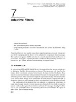
3. Click on the icon to “Create Profile Area” which is the fourth icon from the
top left in Figure 1.14b. Figure 1.14b shows the added profile area for the func-
tion dotp within the C source file dotp4.c.
4. Run the program. Verify the results shown in Figure 1.14b. This indicates that
it takes 138 cycles to execute the function dotp (with no optimization).
22
DSP Development System
FIGURE 1.14. CCS display of project dotp4 for profiling: (a) profile area of code lines 18–26;
(b) profiling function dotp with no optimization; (c) profiling function dotp with optimization.
(a)
(b)
(c)
23
Benchmarking with Optimization (Profiling)
In this section we illustrate how to optimize using one of the optimization options
–o3.The program’s execution speed can be increased by the optimizing C compiler.
Change the compiler option (select Project Æ Build Options) to
–g –o3
and use the same linker options as before (you can type this option directly). The
option –o3 invokes the highest level of compiler optimization. Various compiler
options are described in Ref. 26. Rebuild All (toolbar with three arrows) and load
the executable file (select File Æ Load Program) dotp4.out. Note that after the
executable file is loaded, the entry address for execution is c_int00, as can be ver-
ified by the disassembled file.
Select Debug Æ Run. Verify that it takes now 30 cycles (from 138) to execute
the dotp function, as shown in Figure 1.14c. This is a considerable improvement
using the C compiler optimizer. We further optimize the dot product example
using an intrinsic function in Chapter 3 and code optimization techniques in
Chapter 8.
1.5 SUPPORT PROGRAMS/FILES CONSIDERATIONS
The following support files are used for practically all the examples in this book:
(1) C6xdskinit.c,(2) Vectors_11.asm, and (3) C6xdsk.cmd. For now, the
emphasis associated with these files should be on using them.
1.5.1 Initialization/Communication File (C6xdskinit.c)
The function comm_intr within main in the C source program is located in the
communication file c6xdskinit.c, a partial listing of which is shown in Figure
1.15. The DSK is initialized, then the transmit interrupt INT11 is configured and
enabled.
Two functions for input and output are also included in this communication
support file. The function input_sample returns the input data value from
mcbsp0_read,and the function output_sample calls mcbsp0_write for output.
Interrupt-Driven Program
With an interrupt-driven program, an interrupt is selected (we selected INT11). The
nonmaskable interrupt bit must be enabled as well as the Global Interrupt Enable
(GIE) bit. The appropriate support functions for interrupts are within the support
file C6xdskinterrupts.h and are called from the function comm_intr within
the file C6xdskinit.c.
24
DSP Development System
//C6xdskinit.c Partial listing. Init DSK,AD535,McBSP
#include <c6x.h>
#include “c6xdsk.h”
#include “c6xdskinit.h”
#include “c6xinterrupts.h”
void mcbsp0_write(int out_data) //function for writing
{
int temp;
if (polling) //bypass if interrupt-driven
{
temp = *(unsigned volatile int *)McBSP0_SPCR & 0x20000;
while ( temp == 0)
temp = *(unsigned volatile int *)McBSP0_SPCR & 0x20000;
}
*(unsigned volatile int *)McBSP0_DXR = out_data;
}
int mcbsp0_read() //function for reading
{
int temp;
if (polling) //bypass if interrupt-driven
{
temp = *(unsigned volatile int *)McBSP0_SPCR & 0x2;
while ( temp == 0)
temp = *(unsigned volatile int *)McBSP0_SPCR & 0x2;
}
temp = *(unsigned volatile int *)McBSP0_DRR;
return temp;
}
void comm_poll() //communication with polling
{
polling = 1; //setup for polling
c6x_dsk_init(); //call init DSK function
}
void comm_intr() //communication with interrupt
{
polling = 0; //if interrupt-driven
c6x_dsk_init(); //call init DSK function
config_Interrupt_Selector(11,XINT0); //using transmit interrupt INT11
enableSpecificINT(11); //for specific interrupt
enableNMI(); //enable NMI
enableGlobalINT(); //enable GIE global interrupt
mcbsp0_write(0); //write to SP0
}
void output_sample(int out_data) //added function for output
{
mcbsp0_write(out_data & 0xfffe); //mask out LSB
}
int input_sample() //added function for input
{
return mcbsp0_read(); //read from McBSP0
}
FIGURE 1.15. Partial listing of communication support program (C6xdskinit.c).
25