Tài liệu Electric Motor - động cơ điện ppt
Bạn đang xem bản rút gọn của tài liệu. Xem và tải ngay bản đầy đủ của tài liệu tại đây (3.91 MB, 398 trang )
1
Chapter
1
Electric Motors
J.Kirtley
1.1 Electric Motors
Electric motors provide the driving power for a large and still increasing
part of our modern industrial economy. The range of sizes and types of
motors is large and the number and diversity of applications continues
to expand. The computer on which this book is typed, for example, has
several electric motors inside, in the cooling fan and in the disk drives.
There is even a little motor that is used to eject the removable disk from
its drive.
All around us there are electrical devices that move things around.
Just about everything in one’s life that whine, whirrs or clicks does so
because an electric motor caused the motion.
At the small end of the power scale are motors that drive the hands
in wristwatches, a job that was formerly done by a mechanical spring
mechanism. At the large end of the power scale are motors, rated in the
hundreds of megawatts (MW), that pump water uphill for energy storage.
Somewhat smaller motors, rated in the range of 12 to 15 MW, have
taken over the job of propulsion for cruise ships—a job formerly done by
steam engines or very large, low speed diesel engines.
The flexibility of electric motors and generators and the possibility of
transmitting electric power from place to place makes the use of electric
motors in many drive mechanisms attractive. Even in situations in which
the prime mover is aboard a vehicle, as in diesel-electric locomotives or
passenger ships, electric transmission has displaced most mechanical
or hydraulic transmission. As well, because electric power can be
Downloaded from Digital Engineering Library @ McGraw-Hill (www.digitalengineeringlibrary.com)
Copyright © 2004 The McGraw-Hill Companies. All rights reserved.
Any use is subject to the Terms of Use as given at the website.
Source: Electric Motor Handbook
2 Chapter One
delivered over sliding contacts, stationary power plants can provide
motive power for rail vehicles. The final drive is, of course, an electric
motor.
The expansion of the use of electric motors’ industrial, commercial
and consumer applications is not at an end. New forms of energy storage
systems, hybrid electric passenger vehicles, and other applications not
yet envisioned will require electric motors, in some cases motors that
have not yet been invented.
This book provides a basic and in-depth explanation for the operation
of several different classes of electric motor. It also contains information
about motor standards and application. The book is mostly concerned
with application of motors, rather than on design or production. It takes,
however, the point of view that good application of a motor must rely on
understanding of its operation.
1.2 Types of Motor
It is important to remember at the outset that electric motors operate
through the interaction of magnetic flux and electric current, or flow
of charge. They develop force because a charge moving in a magnetic
field produces a force which happens to be orthogonal to the motion of
the charge and to the magnetic field. Electric machines also produce a
voltage if the conductor in which current can flow moves through the
magnetic field. Describing the interaction in a electric motor requires
both phenomena, since the energy conversion typified by torque times
rotational speed must also be characterized by current times back
voltage.
Electric motors are broadly classified into two categories: AC and
DC. Within those categories there are subdivisions. Recently, with the
development of economical and reliable power electronic components,
the classifications have become less rigorous and many other types of
motor have appeared. However, it is probably best to start with the
existing classifications of motor.
1.2.1 DC motors
DC motors, as the name implies, operate with terminal voltage and
current that is “direct”, or substantially constant. While it is possible to
produce a “true DC” machine in a form usually called “acyclic”, with
homopolar geometry, such machines have very low terminal voltage
and consequently high terminal current relative to their power rating.
Thus all application of DC motors have employed a mechanical switch
or commutator to turn the terminal current, which is constant or DC,
into alternating current in the armature of the machine.
Downloaded from Digital Engineering Library @ McGraw-Hill (www.digitalengineeringlibrary.com)
Copyright © 2004 The McGraw-Hill Companies. All rights reserved.
Any use is subject to the Terms of Use as given at the website.
Electric Motors
Electric Motors 3
DC motors have usually been applied in two broad types of application.
One of these categories is when the power source is itself DC. This is
why motors in automobiles are all DC, from the motors that drive fans
for engine cooling and passenger compartment ventilation to the engine
starter motor.
A second reason for using DC motors is that their torque-speed
characteristic has, historically, been easier to tailor than that of all AC
motor categories. This is why most traction and servo motors have been
DC machines. For example, motors for driving rail vehicles were, until
recently, exclusively DC machines.
The mechanical commutator and associated brushes are problematical
for a number of reasons, and because of this, the advent of cheaper high
power semiconductors have led to applications of AC machines in
situations formerly dominated by DC machines. For example, induction
motors are seeing increased application in railroad traction applications.
The class of machine known as “brushless DC” is actually a synchronous
machine coupled with a set of semiconductor switches controlled by rotor
position. Such machines have characteristics similar to commutator
machines.
1.2.2 AC motors
Electric motors designed to operate with alternating current (AC)
supplies are themselves broadly categorized into two classes: induction
and synchronous. There are many variations of synchronous machines.
AC motors work by setting up a magnetic field pattern that rotates
with respect to the stator and then employing electromagnetic forces to
entrain the rotor in the rotating magnetic field pattern. Synchronous
machines typically have a magnetic field which is stationary with respect
to the rotor and which therefore rotate at the same speed as the stator
magnetic field. In induction motors, the magnetic field is, as the name
implies, induced by motion of the rotor through the stator magnetic
field.
Induction motors are probably the most numerous in today’s economy.
Induction machines are simple, rugged and usually are cheap to produce.
They dominate in applications at power levels from fractional horsepower
(a few hundred watts) to hundreds of horsepower (perhaps half a
megawatt) where rotational speeds required do not have to vary.
Synchronous motors are not as widely used as induction machines
because their rotors are more complex and they require exciters.
However, synchronous motors are used in large industrial applications
in situations where their ability to provide leading power factor helps to
support or stabilize voltage and to improve overall power factor. Also,
in ratings higher than several hundred horsepower, synchronous
Downloaded from Digital Engineering Library @ McGraw-Hill (www.digitalengineeringlibrary.com)
Copyright © 2004 The McGraw-Hill Companies. All rights reserved.
Any use is subject to the Terms of Use as given at the website.
Electric Motors
4 Chapter One
machines are often more efficient than induction machines and so very
large synchronous machines are sometimes chosen over induction
motors.
Operated against a fixed frequency AC source, both synchronous and
induction motors run at (nearly) fixed speed. However, when coupled
with an adjustable frequency AC source, both classes of machine can
form adjustable speed drives. There are some important distinctions
based on method of control:
Brushless DC motors: permanent magnet synchronous machines
coupled with switching mechanisms controlled by rotor position. They
have characteristics similar to permanent magnet commutator
machines.
Adjustable speed drives: synchronous or induction motors coupled to
inverters that generate variable frequency. The speed of the motor is
proportional to the frequency.
Vector control: also called field oriented control, is used to produce
high performance servomechanisms by predicting the location of
internal flux and then injecting current to interact optimally with
that flux.
Universal motors are commutator machines, similar to DC machines,
but are adapted to operation with AC terminal voltage. These machines
are economically very important as large numbers are made for consumer
appliances. They can achieve high shaft speed, and thus relatively high
power per unit weight or volume, and therefore are economical on a
watt-per-unit-cost basis. They are widely used in appliances such as
vacuum cleaners and kitchen appliances.
Variable reluctance machines, (VRMs) also called switched
reluctance machines, are mechanically very simple, operating by the
principle that, under the influence of current excitation, magnetic
circuits are pulled in a direction that increases inductance. They are
somewhat akin to synchronous machines in that they operate at a
speed that is proportional to frequency. However, they typically must
operate with switching power electronics, as their performance is poor
when operating against a sinusoidal supply. VRMs have not yet seen
wide application, but their use is growing because of the simplicity of
the rotor and its consequent ability to operate at high speeds and in
hostile environments.
1.3 Description of the Rest of the Book
The book is organized as follows:
Downloaded from Digital Engineering Library @ McGraw-Hill (www.digitalengineeringlibrary.com)
Copyright © 2004 The McGraw-Hill Companies. All rights reserved.
Any use is subject to the Terms of Use as given at the website.
Electric Motors
Electric Motors 5
Chapter 2 contains a more complete description of the terminology of
electric motors and more fully categorizes the machine types.
Chapter 3 contains the analytical principles used to describe electric
motors and their operation, including loss mechanisms which limit
machine efficiency and power density. This includes the elementary
physics of electromechanical interactions employing the concepts of
stored energy and co-energy; field-based force descriptions employing
the “Maxwell Stress Tensor”; analytical methods for estimating loss
densities in linear materials and in saturating iron; and empirical ways
of describing losses in steel laminations.
Chapter 4 discusses induction machines. In this chapter, the
elementary theory of the induction machine is derived and used to
explain torque-speed curves. Practical aspects of induction motors,
including different classes of motors and standards are described. Ways
of controlling induction motors using adjustable frequency are presented,
along with their limitations. Finally, single-phase motors are described
and an analytic framework for their analysis is presented.
Chapter 5 concerns wound-field synchronous motors. It opens with a
description of the synchronous motor. Analytical descriptions of
synchronous motors and models for dynamic performance estimation
and simulation are included. Standards and ways of testing synchronous
motors are also examined.
Chapter 6 discusses “Brushless DC Motors”. It includes a description
of motor morphology, an analytic framework for brushless motors and a
description of how they are operated.
Chapter 7 examines conventional, commutator type DC machines. It
presents an analytical framework and a description of operation. It also
contains nomenclature and a description of applicable standards.
Chapter 8 investigates other types of electric motors, including several
types which do not fit into the conventional categories but which are
nevertheless important, including types such as universal motors. This
chapter also contains a section on high performance “high torque” motors.
Chapter 9 discusses the acoustic signature production in electric
motors.
Chapter 10 explores the power-electronics systems that make up the
other half of an electromechanical drive system.
Downloaded from Digital Engineering Library @ McGraw-Hill (www.digitalengineeringlibrary.com)
Copyright © 2004 The McGraw-Hill Companies. All rights reserved.
Any use is subject to the Terms of Use as given at the website.
Electric Motors
Downloaded from Digital Engineering Library @ McGraw-Hill (www.digitalengineeringlibrary.com)
Copyright © 2004 The McGraw-Hill Companies. All rights reserved.
Any use is subject to the Terms of Use as given at the website.
Electric Motors
7
Chapter
2
Terminology and Definitions
N.Ghai
2.1 Types of Motor
There are many ways in which electric motors may be categorized or
classified. Some of these are presented below and in Fig. 2.1.
2.1.1 AC and DC
One way of classifying electric motors is by the type of power they
consume. Using this approach, we may state that all electric motors fall
into one or the other of the two categories, viz., AC or DC. AC motors
are those that run on alternating current or AC power, and DC motors
are those that run on direct current, or DC power.
2.1.2 Synchronous and induction
Alternating current motors again fall into two distinct categories,
synchronous or induction. Synchronous motors run at a fixed speed,
irrespective of the load they carry. Their speed of operation is given by
the relationship
where f is the system frequency in Hz and P is the number of poles for
which the stator is wound. The speed given by the above relationship is
called the synchronous speed, and hence the name synchronous motor.
The induction motor, on the other hand, runs very close to but less than
Downloaded from Digital Engineering Library @ McGraw-Hill (www.digitalengineeringlibrary.com)
Copyright © 2004 The McGraw-Hill Companies. All rights reserved.
Any use is subject to the Terms of Use as given at the website.
Source: Electric Motor Handbook
8 Chapter Two
the synchronous speed. The difference between the synchronous speed
and the actual speed is called the slip speed. The slip speed of any
induction motor is a function of its design and of desired performance.
Further, for a given motor, the slip speed and the running speed vary
with the load. The running speed decreases as the load on the motor is
increased.
2.1.3 Salient-pole and cylindrical-rotor
Synchronous motors fall into two broad categories defined by their
method of construction. These are salient-pole motors and cylindrical-
rotor motors. High-speed motors, those running at 3600 r/min with 60
Hz supply, are of the cylindrical-rotor construction for mechanical
strength reasons, whereas slower speed motors, those running at 1800
r/min and slower, are mostly of the salient-pole type.
2.1.4 Single-phase and three-phase motors
All AC motors may also be classified as single-phase and multiphase
motors, depending on whether they are intended to run on single-phase
supply or on multiphase supply. Since the distribution systems are
universally of the three-phase type, multiphase motors are almost always
of the three-phase type. Single-phase motors are limited by the power
they can produce, and are generally available in sizes up to only a few
horsepower, and in the induction motor variety only. Synchronous motors
are usually available in three-phase configurations only.
2.1.5 Other variations
Many variations of the basic induction and synchronous motors are
available. These include but are not limited to the synchronous-induction
motor, which is essentially a wound-rotor-induction motor supplied with
DC power to its rotor winding to make it run at synchronous speed; the
Figure 2.1 Classification of AC and DC motors.
Downloaded from Digital Engineering Library @ McGraw-Hill (www.digitalengineeringlibrary.com)
Copyright © 2004 The McGraw-Hill Companies. All rights reserved.
Any use is subject to the Terms of Use as given at the website.
Terminology and Definitions
Terminology and Definitions 9
permanent-magnet motor in which the field excitation is provided by
permanent magnets; the reluctance motor in which the surface of the
rotor of a squirrel-cage induction motor is shaped to form salient-pole
structures causing the motor to run up to speed as an induction motor
and pull into synchronism by reluctance action and operate at
synchronous speed; and the ac-commutator motor or universal motor,
which possesses the wide speed range and higher starting torque
advantages of DC motor, to name a few. One could also include here
single-phase induction motor variations based on the method of starting
used—the split-phase motor, the capacitor-start motor, the resistance-
start motor, and the shaded-pole motor.
2.2 Insulation System Classes
The classification of winding insulation systems is based on their
operating temperature capabilities. These classes are designated by the
letters A, E, B, F, and H. The operating temperatures for these insulation
classes are shown in Table 2.1.
These temperatures represent the maximum allowable operating
temperature of the winding at which, if the motor were operated in a
clean, dry, free-from-impurities environment at up to 40 hours per week,
an operation life of 10 to 20 years could be expected, before the insulation
deterioration due to heat destroys its capability to withstand the applied
voltage.
The temperatures in the Table 2.1 are the maximum temperatures
existing in the winding, or the hot spot temperatures, and are not the
average winding temperatures. It is generally assumed that in a
welldesigned motor, the hot spot is approximately 10°C higher than the
average winding temperature. This yields the allowable temperature rises
(average, or rises by resistance) in an ambient temperature not exceeding
40°C, that one finds in standards. These are shown in Table 2.2.
Class A insulation is obsolete, and no longer in use. Class E insulation
is not used in the United States, but is common in Europe. Class B is
TABLE 2.2 Allowable Temperature Rises
TABLE 2.1 Operating Temperatures for Insulation System Classes
Downloaded from Digital Engineering Library @ McGraw-Hill (www.digitalengineeringlibrary.com)
Copyright © 2004 The McGraw-Hill Companies. All rights reserved.
Any use is subject to the Terms of Use as given at the website.
Terminology and Definitions
10 Chapter Two
the most commonly specified insulation. Class F is slowly winning favor,
although for larger motors in the United States, the users tend to specify
class F systems with class B temperature rises to improve the life
expectancy of the windings. Class H systems are widely specified in
synchronous generators up to 5 mW in size.
2.3 Codes and Standards
Both national and international standards exist for electric motors. For
the most part, these apply to general purpose motors. However, in the
United States, some definite purpose standards also exist which are
industry or application specific. Examples of the latter are the IEEE
841, which applies to medium size motors for petroleum and chemical
applications, American Petroleum Institute standards API 541 (large
induction motors) and API 546 (large synchronous motors), both for
petroleum and chemical industry applications, and the American
National Standards Institute standard ANSI C50.41 for large induction
motors for generating station applications.
In the United States, in general, the Institute of Electrical and
Electronics Engineers (IEEE) writes standards for motor testing and test
methods, and the National Electrical Manufacturers Association (NEMA)
writes standards for motor performance. In the international field, the
International Electrotechnical Commission (IEC), which is a voluntary
association of countries, writes all standards applicable to electric motors.
U.S. and international standards that apply to electric motors are:
n NEMA MG1-1993, Rev 4, “Motors and Generators.”
n IEEE Std 112–1996, “IEEE Standard Test Procedure for Polyphase
Induction Motors and Generators.”
n IEEE Std 115–1983, “IEEE Guide: Test Procedures for Synchronous
Machines.”
n IEEE Std 522–1992, “IEEE Guide for Testing Turn-to-Turn Insula-
tion on Form-Wound Stator Coils for Alternating Current Rotating
Electric Machines.”
n IEC 34–1, 1996, 10
th
ed., “Rotating Electrical Machines, Part 1: Rat-
ing and Performance.”
n IEC 34–1, Amendment 1, 1997, “Rotating Electrical Machines, Part
1: Rating and Performance.”
n IEC 34–2, 1972, “Rotating Electrical Machines, Part 2: Methods of
Determining Losses and Efficiency of Rotating Electrical Machinery
from Tests.”
n IEC 34–2, Amendment 1, 1995 and Amendment 2, 1996, “Rotating
Electrical Machines, Part 2: Methods of Determining Losses and
Efficiency of Rotating Electrical Machinery from Tests.”
Downloaded from Digital Engineering Library @ McGraw-Hill (www.digitalengineeringlibrary.com)
Copyright © 2004 The McGraw-Hill Companies. All rights reserved.
Any use is subject to the Terms of Use as given at the website.
Terminology and Definitions
Terminology and Definitions 11
n IEC 34–5,1991, “Rotating Electrical Machines, Part 5: Classification
of Degrees of Protection Provided by Enclosures of Rotating Electri-
cal Machines (IP Code).”
n IEC 34–6, 1991, “Rotating Electrical Machines, Part 6: Methods of
Cooling (IC Code).”
n IEC 34–9, 1990 and 2/979/FDIS, 1997, “Rotating Electrical Machines,
Part 9, “Noise Limits.”
n IEC 34–12, 1980, “Rotating Electrical Machines, Part 12: Starting
Performance of Single-speed, Three-phase Cage Induction Motors for
Voltages up to and Including 600 Volts.”
n IEC 34–14, 1990 and 2/940/FDIS, 1996, “Rotating Electrical Machines,
Part 14: Mechanical Vibration of Certain Machines with Shaft Heights
56 mm and Larger.”
n IEC 34–15,1995, “Rotating Electric Machines, Part 15: Impulse Volt-
age Withstand Levels of Rotating AC Machines with Form-wound
Coils.”
n IEC 38, 1983, “IEC Standard Voltages.”
n IEC 72–1, 1991, “Dimension and Output Series for Rotating Electri-
cal Machines.”
Downloaded from Digital Engineering Library @ McGraw-Hill (www.digitalengineeringlibrary.com)
Copyright © 2004 The McGraw-Hill Companies. All rights reserved.
Any use is subject to the Terms of Use as given at the website.
Terminology and Definitions
Downloaded from Digital Engineering Library @ McGraw-Hill (www.digitalengineeringlibrary.com)
Copyright © 2004 The McGraw-Hill Companies. All rights reserved.
Any use is subject to the Terms of Use as given at the website.
Terminology and Definitions
13
Chapter
3
Fundamentals of Electromagnetic
Forces and Loss Mechanisms
J.Kirtley
3.1 Introduction
This chapter covers some of the fundamental processes involved in
electric machinery. In the section on energy conversion processes are
examined the two major ways of estimating electromagnetic forces: those
involving thermodynamic arguments (conservation of energy), and field
methods (Maxwell’s Stress Tensor). In between these two explications
is a bit of description of electric machinery, primarily there to motivate
the description of field based force calculating methods.
The section dealing with losses is really about eddy currents in both
linear and nonlinear materials and about semi-empirical ways of
handling iron losses and exciting currents in machines.
3.2 Energy Conversion Process
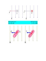
In a motor, the energy conversion process (see Fig. 3.1) can be thought
of in simple terms. In “steady state”, electric power input to the
machine is just the sum of electric power inputs to the different phase
terminals
Mechanical power is torque times speed
Downloaded from Digital Engineering Library @ McGraw-Hill (www.digitalengineeringlibrary.com)
Copyright © 2004 The McGraw-Hill Companies. All rights reserved.
Any use is subject to the Terms of Use as given at the website.
Source: Electric Motor Handbook
14 Chapter Three
and the sum of the losses is the difference
It will sometimes be convenient to employ the fact that, in most
machines, dissipation is small enough to approximate mechanical
power with electrical power. In fact, there are many situations in
which the loss mechanism is known well enough that it can be
idealized away. The “thermodynamic” arguments for force density
take advantage of this and employ a “conservative” or lossless energy
conversion system.
3.2.1 Energy approach to
electromagnetic forces
To start, consider some electromechanical system which has two sets of
“terminals”, electrical and mechanical, as shown in Fig. 3.2. If the system
stores energy in magnetic fields, the energy stored depends on the state
of the system, defined by, in this case, two of the identifiable variables:
flux (), current (i) and mechanical position (x). In fact, with only a little
reflection, you should be able to convince yourself that this state is a
Figure 3.1 Energy conversion process.
Figure 3.2 Conservative magnetic fleld system.
Downloaded from Digital Engineering Library @ McGraw-Hill (www.digitalengineeringlibrary.com)
Copyright © 2004 The McGraw-Hill Companies. All rights reserved.
Any use is subject to the Terms of Use as given at the website.
Fundamentals of Electromagnetic Forces and Loss Mechanisms
Fundamentals of Electromagnetic Forces and Loss Mechanisms 15
single-valued function of two variables and that the energy stored is
independent of how the system was brought to this state.
Now, all electromechanical converters have loss mechanisms and so
are not themselves conservative. However, the magnetic field system
that produces force is, in principle, conservative in the sense that its
state and stored energy can be described by only two variables. The
“history” of the system is not important.
It is possible to choose the variables in such a way that electrical
power into this conservative system is
Similarly, mechanical power out of the system is
The difference between these two is the rate of change of energy stored
in the system
It is then possible to compute the change in energy required to take the
system from one state to another by
where the two states of the system are described by a=(
a
, x
a
) and
b=(
b
, x
b
).
If the energy stored in the system is described by two-state variables,
and x, the total differential of stored energy is
and it is also
so that we can make a direct equivalence between the derivatives and
Downloaded from Digital Engineering Library @ McGraw-Hill (www.digitalengineeringlibrary.com)
Copyright © 2004 The McGraw-Hill Companies. All rights reserved.
Any use is subject to the Terms of Use as given at the website.
Fundamentals of Electromagnetic Forces and Loss Mechanisms
16 Chapter Three
This generalizes in the case of multiple electrical terminals and/or
multiple mechanical terminals. For example, a situation with multiple
electrical terminals will have
In the case of rotary, as opposed to linear, motion has in place of force f
e
and displacement x, torque T
e
and angular displacement
.
In many cases, we might consider a system which is electrically
linear, in which case inductance is a function only of the mechanical
position x
In this case, assuming that the energy integral is carried out from =0
(so that the part of the integral carried out over x is zero)
This makes
Note that this is numerically equivalent to
This is true only in the case of a linear system. Note that substituting
L(x)i= too early in the derivation produces erroneous results: in the
case of a linear system, it is a sign error, but in the case of a nonlinear
system, it is just wrong.
3.2.2 Co-energy
Often, systems are described in terms of inductance rather than its
reciprocal, so that current, rather than flux, appears to be the relevant
variable. It is convenient to derive a new energy variable, co-energy, by
Downloaded from Digital Engineering Library @ McGraw-Hill (www.digitalengineeringlibrary.com)
Copyright © 2004 The McGraw-Hill Companies. All rights reserved.
Any use is subject to the Terms of Use as given at the website.
Fundamentals of Electromagnetic Forces and Loss Mechanisms
Fundamentals of Electromagnetic Forces and Loss Mechanisms 17
and in this case, it is quite easy to show that the energy differential is
(for a single mechanical variable) simply
so that force produced is
Consider a simple electric machine example in which there is a single
winding on a rotor (call it the field winding) and a polyphase
armature. Suppose the rotor is round so that we can describe the flux
linkages as
Now, this system can be simply described in terms of co-energy. With
multiple excitation it is important to exercise some care in taking the
co-energy integral (to ensure that it is taken over a valid path in the
multi-dimensional space). In this case, there are actually five dimensions,
but only four are important since the rotor can be positioned with all
currents at zero so there is no contribution to co-energy from setting
rotor position. Suppose the rotor is at some angle
and that the four
currents have values i
a0
, i
b0
, i
c0
and i
f0
. One of many correct path integrals
to take would be
Downloaded from Digital Engineering Library @ McGraw-Hill (www.digitalengineeringlibrary.com)
Copyright © 2004 The McGraw-Hill Companies. All rights reserved.
Any use is subject to the Terms of Use as given at the website.
Fundamentals of Electromagnetic Forces and Loss Mechanisms
18 Chapter Three
The result is
If the rotor is round so that there is no variation of the stator inductances
with rotor position
, torque is easily given by
3.2.3 Generalization to continuous media
Consider a system with not just a multiplicity of circuits, but a con-
tinuum of current-carrying paths. In that case, we could identify the
co-energy as
where that area is chosen to cut all of the current carrying conductors.
This area can be picked to be perpendicular to each of the current
filaments since the divergence of current is zero. The flux is calculated
over a path that coincides with each current filament (such paths exist
since current has zero divergence). Then the flux is
Now, if the vector potential for which the magnetic flux density is
Downloaded from Digital Engineering Library @ McGraw-Hill (www.digitalengineeringlibrary.com)
Copyright © 2004 The McGraw-Hill Companies. All rights reserved.
Any use is subject to the Terms of Use as given at the website.
Fundamentals of Electromagnetic Forces and Loss Mechanisms
Fundamentals of Electromagnetic Forces and Loss Mechanisms 19
the flux linked by any one of the current filaments is
where is the path around the current filament. This implies directly
that the co-energy is
Now it is possible to make coincide with and be parallel to the
current filaments, so that
3.2.4 Permanent magnets
Permanent magnets are becoming an even more important element in
electric machine systems. Often systems with permanent magnets are
approached in a relatively ad-hoc way, made equivalent to a current
that produces the same MMF as the magnet itself.
The constitutive relationship for a permanent magnet relates the
magnetic flux density to magnetic field and the property of the
magnet itself, the magnetization
Now, the effect of the magnetization is to act as if there were a current
(called an amperian current) with density
Note that this amperian current “acts” just like ordinary current in
making magnetic flux density. Magnetic co-energy is
Next, note the vector identity
Now
Downloaded from Digital Engineering Library @ McGraw-Hill (www.digitalengineeringlibrary.com)
Copyright © 2004 The McGraw-Hill Companies. All rights reserved.
Any use is subject to the Terms of Use as given at the website.
Fundamentals of Electromagnetic Forces and Loss Mechanisms
20 Chapter Three
Then, noting that
The first of these integrals (closed surface) vanishes if it is taken over a
surface just outside the magnet, where is zero. Thus the magnetic co-
energy in a system with only a permanent magnet source is
Adding current carrying coils to such a system is done in the obvious
way.
3.2.5 Electric machine description
Actually, this description shows a conventional induction motor. This is
a very common type of electric machine and will serve as a reference
point. Most other electric machines operate in a fashion which is the
same as the induction machine or which differ in ways which are easy
to reference to the induction machine.
Consider the simplified machine drawing shown in Fig. 3.3. Most
machines, but not all, have essentially this morphology. The rotor of the
machine is mounted on a shaft which is supported on some sort of
bearing(s). Usually, but not always, the rotor is inside. Although this
rotor is round, this does not always need to be the case. Rotor conductors
Figure 3.3 Form of electric machine.
Downloaded from Digital Engineering Library @ McGraw-Hill (www.digitalengineeringlibrary.com)
Copyright © 2004 The McGraw-Hill Companies. All rights reserved.
Any use is subject to the Terms of Use as given at the website.
Fundamentals of Electromagnetic Forces and Loss Mechanisms
Fundamentals of Electromagnetic Forces and Loss Mechanisms 21
are shown, but sometimes the rotor has permanent magnets either
fastened to it or inside, and sometimes (as in Variable Reluctance
Machines), it is just an oddly shaped piece of steel. The stator is, in this
drawing, on the outside and has windings. With most machines, the
stator winding is the armature, or electrical power input element. (In
dc and Universal motors, this is reversed, with the armature contained
on the rotor.)
In most electrical machines, the rotor and the stator are made of
highly magnetically-permeable materials: steel or magnetic iron. In
many common machines such as induction motors, the rotor and stator
are both made up of thin sheets of silicon steel. Punched into those
sheets are slots which contain the rotor and stator conductors.
Figure 3.4 is a picture of part of an induction machine distorted so
that the air-gap is straightened out (as if the machine had infinite radius).
This is actually a convenient way of drawing the machine and, we will
find, leads to useful methods of analysis.
What is important to note for now is that the machine has an air gap
g which is relatively small (that is, the gap dimension is much less than
the machine radius r). The air-gap also has a physical length
ᐍ
. The
electric machine works by producing a shear stress in the air-gap (with
of course side effects such as production of “back voltage”). It is possible
to define the average air-gap shear stress
. Total developed torque is
force over the surface area times moment (which is rotor radius)
Power transferred by this device is just torque times speed, which
is the same as force times surface velocity, since surface velocity is
u=r⍀
Figure 3.4 Windings in slots.
Downloaded from Digital Engineering Library @ McGraw-Hill (www.digitalengineeringlibrary.com)
Copyright © 2004 The McGraw-Hill Companies. All rights reserved.
Any use is subject to the Terms of Use as given at the website.
Fundamentals of Electromagnetic Forces and Loss Mechanisms
22 Chapter Three
If active rotor volume is V
r
=
r
2
ᐍ
, the ratio of torque to volume is just
Now, determining what can be done in a volume of machine involves
two things. First, it is clear that the calculated volume is not the whole
machine volume, since it does not include the stator. The actual estimate
of total machine volume from the rotor volume is actually quite complex
and detailed. Second, estimate the value of the useful average shear
stress. Suppose both the radial flux density Br and the stator surface
current density Kz are sinusoidal flux waves of the form
Note that this assumes these two quantities are exactly in phase, or
oriented to ideally produce torque, and this will produce an “optimistic”
estimate. Then the average value of surface traction is
This actually makes some sense in view of the empirically derived
Lorentz Force Law: Given a (vector) current density and a (vector) flux
density, in the absence of magnetic materials (those with permeability
different from that of free space), the observed force on a conductor is
where
is the vector describing current density (A/m
2
) and is the
magnetic flux density (T). This is actually enough to describe the forces
we see in many machines, but since electric machines have permeable
magnetic material and since magnetic fields produce forces on permeable
material even in the absence of macroscopic currents, it is necessary to
observe how force appears on such material. A suitable empirical
expression for force density is
where is the magnetic field intensity and µ is the permeability.
Now, note that current density is the curl of magnetic field intensity,
so that
Downloaded from Digital Engineering Library @ McGraw-Hill (www.digitalengineeringlibrary.com)
Copyright © 2004 The McGraw-Hill Companies. All rights reserved.
Any use is subject to the Terms of Use as given at the website.
Fundamentals of Electromagnetic Forces and Loss Mechanisms
Fundamentals of Electromagnetic Forces and Loss Mechanisms 23
And, since
force density is
This expression can be written by components: the component of force
in the i’th dimension is
Now, the divergence of magnetic flux density is
and
but since the last term is zero, the force density is
where the Kroneker delta ␦
ik
=1 if i=k, 0 otherwise. Note that this force
density is in the form of the divergence of a tensor
or
Downloaded from Digital Engineering Library @ McGraw-Hill (www.digitalengineeringlibrary.com)
Copyright © 2004 The McGraw-Hill Companies. All rights reserved.
Any use is subject to the Terms of Use as given at the website.
Fundamentals of Electromagnetic Forces and Loss Mechanisms
24 Chapter Three
In this case, force on some object that can be surrounded by a closed
surface can be found by using the divergence theorem
or, if the surface traction is
i
=⌺
k
T
ik
n
k
, where n is the surface normal
vector, then the total force in direction i is just
The interpretation of all of this is less difficult than the notation suggests.
This field description of forces gives a simple picture of surface traction,
the force per unit area on a surface. Integrate this traction over the
area of some body to get the whole force on the body.
Note one more thing about this notation. Sometimes when subscripts
are repeated as they are here, the summation symbol is omitted. Thus
i
=⌺
k
T
ik
n
k
=T
ik
n
k
.
Now, in the case of a circular cylinder and torque, one can compute
the circumferential force by noting that the normal vector to the cylinder
is just the radial unit vector, and then the circumferential traction must
simply be
Assuming that there are no fields inside the surface of the rotor, simply
integrating this over the surface gives azimuthal force, and then
multiplying by radius (moment arm) gives torque. The last step is to
note that, if the rotor is made of highly permeable material, the azimuthal
magnetic field is equal to surface current density.
3.3 Surface Impedance of
Uniform Conductors
The objective of this section is to describe the calculation of the surface
impedance presented by a layer of conductive material. Two problems
are considered here. The first considers a layer of linear material backed
up by an infinitely permeable surface. This is approximately the situation
presented by, for example, surface-mounted permanent magnets and is
probably a decent approximation to the conduction mechanism that
would be responsible for loss due to asynchronous harmonics in these
Downloaded from Digital Engineering Library @ McGraw-Hill (www.digitalengineeringlibrary.com)
Copyright © 2004 The McGraw-Hill Companies. All rights reserved.
Any use is subject to the Terms of Use as given at the website.
Fundamentals of Electromagnetic Forces and Loss Mechanisms
Fundamentals of Electromagnetic Forces and Loss Mechanisms 25
machines. It is also appropriate for use in estimating losses in solid-
rotor induction machines and in the poles of turbogenerators. The second
problem concerns saturating ferromagnetic material.
3.3.1 Linear case
The situation and coordinate system are shown in Fig. 3.5. The
conductive layer is of thickness T and has conductivity
and permeability
µ
0
. To keep the mathematical expressions within bounds, assume
rectilinear geometry. This assumption will present errors which are small
to the extent that curvature of the problem is small compared with the
wavenumbers encountered. Presume that the situation is excited, as it
would be in an electric machine, by a current sheet of the form
In the conducting material, the diffusion equation must be satisfied
In view of the boundary condition at the back surface of the material,
taking that point to be y=0, a general solution for the magnetic field in
the material is
where the coefficient
␣
satisfies
and note that the coefficients above are chosen so that
has no
divergence.
Figure 3.5 Axial view of magnetic field problem.
Downloaded from Digital Engineering Library @ McGraw-Hill (www.digitalengineeringlibrary.com)
Copyright © 2004 The McGraw-Hill Companies. All rights reserved.
Any use is subject to the Terms of Use as given at the website.
Fundamentals of Electromagnetic Forces and Loss Mechanisms