Tài liệu CDMA truy cập và chuyển mạch P4 docx
Bạn đang xem bản rút gọn của tài liệu. Xem và tải ngay bản đầy đủ của tài liệu tại đây (372.72 KB, 23 trang )
4
Code Division Switching
4.1 Overview
In this chapter we present and analyze the switching architecture of the exchange node
for switched CDMA networks. As we have discussed in the previous chapter, in such a
network CDMA traffic channels will be routed by the exchange node from any input
to any output link.
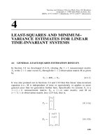
If we consider a traditional switching approach, the exchange node can be
implemented as shown in Figure 4.1. In this case we assume that Time Multiplexed
Switching (TMS) is used to provide the switch functions. As shown, after the
despreading operation, all CDMA user channels are time multiplexed, then routed
to the destination output port by the TMS, demultiplexed, spread again, and
then combined for the output CDMA channel. The TMS approach, however,
introduces additional complexities, because the switch input and output ports
require time multiplexing, while the incoming and outgoing signal is based on code
multiplexing. (In traditional switching methods such as time slot interchangers or
space switching, traffic channels are time multiplexed in each input or output port.)
Also, the complexity for a strictly nonblocking TMS switch fabric is significant.
This means that in applications such as SS/CDMA where the available power
and mass at the satellite are limited, TMS may not be an efficient switching
approach.
Therefore, we propose an alternative switching method which is based on code
division. That is, the signals in the switch are distinguished and routed according
to their spreading codes. This method is directly applicable in all switched CDMA
networks such as SS/CDMA, BS/CDMA or CS/CDMA. In this chapter we provide
illustrative Code Division Switch (CDS) architectures, performance and complexity
evaluation analysis and comparisons with traditional switching methods. As shown,
the proposed CDS architecture is nonblocking and its hardware complexity and
speed is proportional to the size of the switch. Also, the CDS routes the CDMA
user channels without introducing interference. The switch performance evaluation
includes the amplitude distribution of the combined signal in the CDS bus and the
interference evaluation of the end-to-end link in the proposed network applications.
The code division switch performance evaluation will utilize the satellite switching
(SS/CDMA) as a basis for study. This work was originally presented in references [1]
and [2].
CDMA: Access and Switching: For Terrestrial and Satellite Networks
Diakoumis Gerakoulis, Evaggelos Geraniotis
Copyright © 2001 John Wiley & Sons Ltd
ISBNs: 0-471-49184-5 (Hardback); 0-470-84169-9 (Electronic)
84 CDMA: ACCESS AND SWITCHING
DESPR
M
U
X
:
DESPR
RF/BB
DESPR
DESPR
M
U
X
:
RF/BB
D
E
M
U
X
SPREAD
SPREAD
:
Σ
BB/RF
D
E
M
U
X
SPREAD
SPREAD
:
Σ
BB/RF
:
NxN
Switch
TMS
Receiver
Transmitter
Input
Link
1
N
Outpu
Link
1
N
Figure 4.1 The exchange node in a SW/CDMA using TMS.
4.2 Switched CDMA (SW/CDMA) Architectures
In this section we examine the network and switch architectures in SS/CDMA and
SW/CDMA for terrestrial wireless and cable applications. We also examine traditional
switch architectures (such as the TMS) for routing CDMA channels, and present a
CDS method for routing time multiplexed channels.
4.2.1 Satellite Switched CDMA (SS/CDMA) System
As we have described in the previous chapter, the on-board design of a SS/CDMA
system provides the CDS modules, the switch control unit and the transceivers of the
control channels (Access and Broadcast). The switching and control architecture at
the exchange node on board the satellite is illustrated in Figure 4.2.
Traffic channels are routed from uplink to downlink beams via the switch modules
without data decoding on board the satellite. The Traffic channel modulation and
spreading processes are based on the Spectrally Efficient CDMA (SE-CDMA) which
are illustrated in Figures 3.27 and 3.28 of Chapter 3. The SE-CDMA spreading process
requires the following codes: (1) a set of orthogonal codes w
k
having a chip rate R
c1
assigned to satellite users k =1, 2, , L
u
within each beam; (2) pseudo-random (PN)
codes c
i
with a chip rate R
c1
assigned to satellite beams i =1, 2, N;and(3)aset
of orthogonal codes w
i
with a chip rate R
c2
for orthogonal isolation of L
b
satellite
beams, i =1, 2, ,L
b
.
The PN-codes spreading rate R
c1
is the same as the rate of the user orthogonal
codes w
k
. The orthogonal codes w
i
, however, require a higher spreading rate R
c2
=
L
b
R
c1
. The process of spreading a previously spread signal at a higher rate is called
CODE DIVISION SWITCHING 85
Uplink Traffic Channels
Beam (1)
Beam (i)
Beam (N)
Beam (1)
Beam (j)
Beam (N)
Access Control Channels
R
C
V
T
R
N
Beam (1)
Beam (i)
Beam (N)
Beam (1)
Beam (j)
Beam (N)
Broadcast Control Channels
CONTROL
UNIT
NXN
CODE DIVISION SWITCH (CDS)
MODULES
Downlink Traffic Channels
Figure 4.2 The CDS control system.
overspreading (see Chapter 1, Section 1.4.2). When L
b
= 4 the system is called a Fully
Orthogonal (FO), when L
b
= 2, a Mostly Orthogonal (MO), and when L
b
= 1 (i.e.
R
c1
= R
c2
= R
c
) is called it Semi-Orthogonal (SO) SE-CDMA. Hence, the SE-CDMA
will eliminate the interference between users within each beam, as well as between the
L
b
beams in the cluster, while it allows a frequency reuse of one.
In a particular implementation, presented in Appendix 4A, R
c2
=9.8304 Mc/s and
L
u
= 60. Also, the orthogonal codes can be either Quadratic Residue (QR) codes or
Walsh codes when the length L =2
k
.
The Code Division Switch (CDS)
The proposed CDS architecture is shown in Figure 4.3. Each uplink CDMA channel
is first converted into an Intermediate Frequency (IF) and then into baseband (BB)
without demodulating the incoming signal (switching at IF has also been considered).
After that, the signal is despread by the uplink orthogonal beam code w
i
and the
PN beam code c
i
(see Figure 4.4-A). Each particular user signal is then recovered by
the Traffic Channel Recovery Circuit (TCRC) shown in Figure 4.5. This is achieved
by despreading with the user’s uplink orthogonal code w
k
. The signal will then be
respread with the user (w
m
)andbeam(c
j
, w
j
) downlink codes.
Finally, the signal will be overspread again by an orthogonal (switch) code w
n
(n =1, 2, , L
s
), having a chip rate R
c3
= L
s
R
c2
. This step of overspreading will
achieve orthogonal separation of all user Traffic channels in the system, and thus can
be combined (summed up) into a common bus. The number of w
n
codes, L
s
,isequal
to the number N of switch ports (L
s
= N), if no prior orthogonal separation between
uplink beams exists. In such a case the rate is R
c3
= N ·R
c1
. The SE-CDMA scheme,
however (shown in Figures 3.27 and 3.28), has the L
b
beams already orthogonalized.
Hence, L
s
= N/L
b
and R
c3
=(N/L
b
) · R
c2
. Each uplink beam in the cluster will
86 CDMA: ACCESS AND SWITCHING
Σ
RF/BB
UPLINK
BEAM-1
Beam
Despread
TCRC-L
TCRC-1
TCRC-L
TCRC-1
BEAM- N
BEAM-1
BEAM-N
From the CU
From the CU
CDB
DOWNLINK
CDB: Code Division
on
Bus
De-overspreading
BB/RF
De-overspreading
BB/RF
Beam
Despread
RF/BB
Figure 4.3 The Code Division Switch (CDS) module.
then be overspread by the same w
n
orthogonal code (n =1, 2 ,N/L
b
). For L
b
=4
(FO/SE-CDMA), N =32andL
s
= 8, the chip rate is R
c3
=78.6432 Mc/s. (See the
example presented in Appendix 4A.) The I and Q components are combined (summed-
up) in parallel by two separate adders (in the case where both I and Q are summed,
theratewillbeR
c3
=2N ·R
c1
). The steps of overspreading, the codes involved, and
the corresponding chip rates for this application are shown in Figure 4.6.
After overspreading, all incoming (I or Q) signals are combined (summed up) into
a (I or Q) bit stream called a Code Division Bus (CDB). The CDB then contains all
Traffic channels spread by their corresponding downlink user and beam destination
codes. Hence, each downlink beam may be recovered by the de-overspreading circuit
shown in Figure 4.4-B, and routed to its destination port. The signal will then
be converted into an IF, and subsequently into an RF frequency for downlink
transmission. The set of all codes in the TCRCs for routing the Traffic channels
to their destinations are supplied by a Control Unit (CU). The number of TCRCs
required in each beam is L
u
, and is equal to the number of Traffic channels per beam
(beam capacity), so that no blocking occurs in the switch. Also, uplink orthogonal
codes, w
k
and w
i
, require synchronization in order to maintain orthogonality. This is
achieved by a synchronization mechanism which adjusts the transmission time of each
user so that all codes are perfectly aligned upon reception at the TCRC despreaders.
An equivalent functional arrangement of the code division switch is shown in
Figure 4.7. The corresponding circuits for Traffic channel recovery and respreading
are shown in Figure 4.8. In this architecture the incoming signal, after conversion
to baseband, is despread by the uplink beam orthogonal code (beam recovery), and
CODE DIVISION SWITCHING 87
B The De-overspreading circuit
R
c3
R
c3
R
c2
L
s
T
c3
W
n
L
b
T
c2
∫
0
W
i
R
c2
R
c2
R
c1
R
c1
A The Beam Despreader
L
b
T
c2
C
i
L
b
T
c2
∫
0
L
s
T
c3
∫
0
L
s
T
c3
∫
0
R
c2
L
s
T
c3
Figure 4.4 The beam-despreading and the de-overspreading circuits.
then overspread so that it can be combined (summed up) into the Code Division Bus
(CDB). Overspreading by the switch codes w
n
allows orthogonal separation in the
CDB between all uplink beams or incoming switch inputs. The beam recovery and
overspreading (BR&OS) operation is illustrated in Figure 4.8-A. A Traffic channel
recovery and respreading (TCR&RS) circuit recovers the desired Traffic channel from
the CDB by de-overspreading its signal with the corresponding switch orthogonal code
(w
n
, n =1, , n), and then despreading it with the uplink user code w
k
. After recovery,
Traffic channels are routed to the desired downlink beam (output port) by respreading
them with the corresponding destination user (w
m
)andbeam(c
j
,w
j
)codes.The
TCR&RS circuit is shown in Figure 4.8-B. At the output, all TCR&RS circuits having
the same destination beam will be combined (summed up) and converted into the RF
carrier for downlink transmission. Each output beam requires L
u
TCR&RS circuits
equal to the maximum number of Traffic channels per beam.
Comparing the two architectures presented above (Figures 4.3 and 4.7), we observe
that both of them perform the same functions, but in a different order. In the
first configuration (Figure 4.3), Traffic Channel Recovery (TCR) takes place before
channels are combined into the CDB, while in the alternative configuration (Figure
4.7), TCR takes place after the CDB. In the alternative configuration, only beam
recovery takes place before the CDB to the rate R
c1
= L
u
R
s
.Inbothcases,theCDB
has the same rate which is R
c3
(R
c3
= NR
c1
= L
s
R
c2
and L
s
= N/L
b
). The relation
between chip rates is shown in Figure 4.6. Performance comparisons between the above
CDS configurations are provided in Section 4.3.
In the above CDS architectures, the baseband signal (i.e. the output of the RF
to baseband converter for any M-ary PSK scheme, M ≥ 4), has two components, I
88 CDMA: ACCESS AND SWITCHING
W
k
Despreading
L
u
T
c2
W
m
n
W
j
Re-Spreading
R
s
R
s
R
c2
R
c2
R
c1
R
c1
R
c3
R
c3
Over-
Spreading
R
c1
W
n
C
i
W
n
C
i
W
m
W
j
L
u
T
c2
∫
0
L
u
T
c2
∫
0
R
c1
R
c1
Figure 4.5 The Traffic Channel Recovery Circuit (TCRC).
and Q. The I and Q outputs are not orthogonal in baseband. Hence, either the I and
Q components must be switched separately (using I and Q signal combiners), or if
a single combiner is used, the speed of overspreading must be doubled (using twice
as many orthogonal codes). Here, we consider the first case in which there is space
separation between the I and Q components as in Figure 4.7.
Time Multiplexed Switching (TMS) of CDMA Channels
In SS/CDMA we may also use Time and/or Space Division switching for routing the
code multiplexed signals. In these cases, the incoming signal is first downconverted to
baseband and despread. Data symbols are then time multiplexed and time slots will be
routed via a Time Slot Interchanger (TSI) or a Space Division Switch (SDS). Figure 4.9
illustrates a Time Division Code Switch (TDCS) consisting of a TSI between the input
despreader and the output respreader. Similarly, a Space Division Code Switch (SDCS)
would consist of despreaders, followed by a space switch, followed by respreaders. The
TSI in the TDCS rearranges the time slots in each frame, while the SDS in the SDCS
provides physical connections during the period of the time slot. The size of a TSI
is limited by practical speed and memory. In space switching, on the other hand,
the limiting factor is the number of cross point connections (N
2
for a nonblocking
cross-bar switch fabric) which may be constrainted by the volume available within the
spacecraft. For large switch sizes, a multi-stage switching network is generally used.
Such a network may consist of TSIs interconnected with a space switch (known as
the Time-Space-Time architecture). The complexity of this approach, however, may
be excessive in satellite switching applications. An implementation example of time
multiplexed switching CDMA channels is given in reference [3].
4.2.2 SW/CDMA Applications in Terrestrial Networks
Terrestrial SW/CDMA applications include wireless CDMA networks for mobile and
fixed services, called Base Station Switched CDMA (BS/CDMA), and coax-cable
CODE DIVISION SWITCHING 89
1
2
60
1
4
T
c2
= 8 T
c3
T
c1
= 4 x T
c2
T
ss
= 60 x T
c1
18
T
c3
R
T
s (Orthogo
R
T
s (Cluster
R
T
s (User Tr
R
T
s
c
c
c
c
c
c
ss
ss
3
3
2
2
1
1
1
8 9 8304 78 6432
1
4 2 4576 9 8304
1
60 40 96 2 4576
1
40 96
==× =
==× =
==× =
==
/
/
/
./
Mc nal Separation of Beams in the Switch)
Mc Beams Orthogonal Separation)
Mc affic Channel Orthogonal Separation)
ks
Unspread
Orth. User
Code
PN Beam
Code
Orth. Beam
Code
Orth.Switch
Code
Uplink Codes
Downlink Codes
Code Rates
W
k
R
c1
g
i
R
c1
R
c2
W
m
c
j
W
i
W
j
W
n
R
c3
R
ss
Figure 4.6 The overspreading relations in the CDS module.
networks having CDMA access for two-way multimedia services called Cable Switched
CDMA (CS/CDMA) (see Chapter 3, Section 3.1).
Base Station Switched CDMA (BS/CDMA)
In BS/CDMA we consider the cases of mobile and fixed service applications: see
references [4] and [5]. In the case of mobile service, we assume that the uplink spreading
consists of a user code g
k
and a cell or cell-sector cover-code c
i
, where both of them
are PN-codes having the same chip rate (as, for example, in the TIA/IS-95 standard).
In the downlink, there are orthogonal user codes W
m
and PN cover-codes c
j
. The code
division switch design in this case is then similar to that in Figures 4.3 or 4.7, but
without the beam codes W
i
and W
j
, while the uplink user code W
k
is replaced with
the PN-code g
k
.
In fixed service applications (such as wireless local loop), we may use PN-codes as in
the mobile case, or orthogonal codes as in SS/CDMA (since synchronization is possible
for nonmobile service), depending on the network application or the propagation
90 CDMA: ACCESS AND SWITCHING
RF/BB: RF to Baseband converter
BR&OS: Beam Recovery and Overspreading
CDB: Code Division Bus
TCR&RS: Traffic Channel Recovery and Respreading
UP LINK
I
Q
RF/ BB
RS&OS
I
Q
Σ
.
.
.
.
.
.
I
1
1
DOWNLINK
.
.
.
.
.
.
.
.
Q
I
I
N
N
C
D
B
Σ
1
Σ
TCR&RC
TCR&RC
Σ
Σ
I
I
Q
Q
L
u
Σ
C
D
B
L
u
L
u
TCR&RC
TCR&RC
TCR&RC
TCR&RC
TCR&RC
TCR&RC
1
1
1
L
u
RF/BB RS&OS
BB/RF
BB/RF
Beam-1
Beam-1
Beam-N
Beam-N
Figure 4.7 An alternative Code Division Switch (CDS) architecture.
characteristics. If we use orthogonal codes, the CDMA spreading design may be based
on the Mostly Orthogonal (MO/SE-CDMA) implementation described in Chapter 3.
In this case, considering multi-sector cells, we use two orthogonal sector-codes for
rejecting the interference from the adjacent sectors. Then, assuming the spreading
circuit of Figure 3.28, the rate R
c
= R
c2
=2R
c1
. The code division switch design in
this case will be the same as in Figures 4.3 or 4.7. Based on the end-to-end interference
analysis presented in Section 4.3, it is recommended that in the BS/CDMA the CDS
also includes both the demodulation/remodulation process and channel decoding and
re-encoding.
Cable Switched CDMA (CS/CDMA)
In CS/CDMA the upstream access is based on a synchronized orthogonal CDMA
as described in reference [6]. The upstream spreading process, unlike SS/CDMA or
BS/CDMA, does not require orthogonal beam or cell-codes, for the reason that CDMA
channels (operating in the same frequency band) are in different coax-cables, and are
thus completely isolated from each other. Upstream user (code) channels within the
cable are then isolated by orthogonal user codes W
k
, while CDMA channels in different
cables do not interfere with each other. Similarly, for the downstream we only use
orthogonal user codes W
m
. The code division switch design in this case will be as in
CODE DIVISION SWITCHING 91
A. The beam recovery and overspreading (BR&OS)
B. The Traffic channel recovery and respreading
W
i
, Beam
Orth. Code
R
c1
W
n
, Switch
Orth. Code
W
k
, User
Orth. Code
R
c3
R
c1
∑
N
1
∑
u
L
1
W
n
, User
Orth. Code
R
ss
C
i
, Beam
PN Code
R
c1
R
c2
De-overspreading
Downlink Respreading
Despreading
∑
Ls
1
W
i
, Beam
Orth. Code
i=1,2, ,L
b
W
n
, Switch
Orth. Code
n=1,2, ,N
R
c2
R
c3
R
c1
C
i
, User
Orth. Code
R
c1
(TCR&RS)
Figure 4.8 The BR&OS and TCR&RS circuits for the alternative CDS module
architecture.
Figures 4.3 or 4.7, but without beam codes W
i
and c
i
in the uplink and W
j
and c
j
in
the downlink.
Based on the end-to-end interference analysis presented in Section 4.3.3, the CDS in
the CS/CDMA application may take full advantage of direct connectivity between end
users, since no demodulation/remodulation, no channel or source decoding/encoding,
and no data buffering are required at the exchange node.
Code Division Switching of Time Multiplexed Channels
Code division switching may also used in systems where Traffic channels at
the input or output links of the exchange node are Time Division Multiplexed
(TDM). In this case the TSI can be replaced by a Code Division Switch. The
CDS architecture in this case is shown in Figure 4.10. The input signals first
are spread with orthogonal code W
m
of the destination port m (m =1, , N)
of the current time slot k (k =1, , L),andthenarecombined(summed
up) into a code division bus (CDB). Each output port signal then is recovered
from the CDB by despreading with the output code W
m
in time slot k.All
signals in the CDB are orthogonal in time and code. The speed of the signal
in the CDB is NR,whereRkb/sis the bit rate at the input or output ports.
Orthogonal codes W
m
are supplied by the control unit on a time-slot by time-slot
basis.
92 CDMA: ACCESS AND SWITCHING
TS I
B
E
A
M
1
1
2
L
1
2
L
1
2
L
1
2
L
B
E
A
M
N
IN
OUT
Beam (1)
RF/BB
Beam
Despread
R
S
Demod
R
S
Demod
Σ
R
s
Mod/Spread
Mod/Spread
Beam
Spread
BB/RF
Beam 1
Σ
R
s
Beam
Spread
BB/RF
Beam N
Sampler
MUX
Sampler
DEMUX
From the
Control Unit
Bean (N)
RF/BB
Beam
Despread
User
Despread
User
Despread
R
S
Demod
R
S
Demod
User
Despread
User
Despread
Mod/Spread
Mod/Spread
Figure 4.9 The Time Division Code Switch (TDCS).
Orthogonal codes with rate NR kb/s destined for ports m and n, respectively.
Σ
1
2
L
Time Frame
Input
Port 1
W
m
Input
Port N
W
n
∫
NTc
0
Output
Port 1
W
1
∫
NTc
0
Output
Port N
W
N
:
:
:
:
:
:
:
:
NXN Code Division Switch
R kb/s
R kb/s
NR kb/s
1
2
L
Time Frame
1
2
L
Time Frame
1
2
L
Time Frame
Wn,Wm:
Figure 4.10 A CDS architecture for time multiplexed channels.
CODE DIVISION SWITCHING 93
4.3 Performance Evaluation of Code Division Switching
In this section we evaluate the interference or noise caused by the switch during the
routing process (in Section 4.3.1), the instantaneous signal amplitude in the code
division bus as a function of the user load (in Section 4.3.2), and the end-to-end
interference for each SW/CDMA application (in Section 4.3.3).
4.3.1 Evaluation of the Switch Interference
Let us consider the SS/CDMA application with the CDS architecture of Figure 4.3,
having an N × N CDS switch module with N input and N output ports. Also, let
s
(n)
I
[l]ands
(n)
Q
[l] denote the I and Q signal samples at times lT
c1
at the n
th
input
port of the switch: 1 ≤ n ≤ N and l = ,−2, −1, 0, 1, 2, The chip duration is
T
c1
=1/R
c1
(see Figure 4.6).
Let w
(n)
I
[m]andw
(n)
Q
[m]form =1, 2, ,N be the overspreading codes used in the
I and Q subports of port n. The result of overspreading is that the m
th
overspreading
chip of the l
th
chip I and Q components, is equal to
N
n=1
s
(n)
I
[l]w
(n)
I
[m],
N
n=1
s
(n)
Q
[l]w
(n)
Q
[m]
=(¯s
I
[l, m], ¯s
Q
[l, m]) ≡ ¯s[l, m]
where m =1, 2, ,N. During de-overspreading at an output port of interest, and for
the signal I of the n = 1 input port, we have:
N
m=1
¯s
I
[l, m]w
(1)
I
[m]=
N
m=1
N
n=1
s
(n)
I
[l]w
(n)
I
[m]
w
(1)
I
[m]
=
N
n=1
s
(n)
I
[l]
N
m=1
w
(n)
I
[m]w
(1)
I
[m]
=
N
n=1
s
(n)
I
[l]δ
I
[n, 1] = s
(1)
I
[l]
where δ
I
[n, 1] =
N
m=1
w
(n)
I
[m]w
(1)
I
[m], and thus δ
I
[n, 1] = 1 if n = 1 and 0 otherwise.
Similarly, we obtain
N
m=1
¯s
Q
[l, m]w
(1)
Q
[m]=s
(1)
Q
[l], and thus both the I and Q
components of the signal of interest (n = 1) are recovered at this output port.
Critical to the above derivation is the assumption that the signals at all the input
ports s
(n)
I
[l]ands
(n)
Q
[l] remain constant (unchanged) over the duration of one chip: T
c
.
It is thus assumed that the N samples of the overspreading codes w
(n)
I
[m]andw
(n)
Q
[m]
(m =1, 2, ,N) are multiplied (modulo-2 added) by the same value (single sample)
of the signals s
(n)
I
[l]ors
(n)
Q
[l] for all n (and l). To guarantee that these chip samples do
not change value within the chip duration, there must be no chip waveform shaping
taking place in the switch. The chip waveform (raised cosine chip filter) is, of course,
used at the input matched filters and at the output of the switch before the signal is
transmitted over the downlink.
Provided that there is no time variation within the duration of the chip, there is no
interference of any type introduced by the CDS. Of course, whatever interference is
already included in the soft inputs (real numbers) s
(n)
I
[l]ands
(n)
Q
[l]atl
th
chip time of
the n
th
input port, is transferred intact to the output port that uses the orthogonal
94 CDMA: ACCESS AND SWITCHING
codes w
(n)
I
[m]andw
(n)
Q
[m] for de-overspreading. The phenomenon of interference
transfer is examined in Section 4.3.3.
In the alternative CDS architecture shown in Figure 4.7, overspreading takes place
after beam despreading, but before user despreading and re-spreading. In this case
the value of the chip amplitude is fixed for the duration of the chip (T
c2
), since the
signal is taken at the output of the matched filter (interchip interference filter). Hence,
neither of the alternative CDS configurations introduce any interference to the Traffic
channels during the switching process.
4.3.2 Signal Amplitude Distribution
As shown in section 4.3.1, the signal samples at the input ports are first modulo-
2 added to the overspreading codes and then added (real addition) together. The
resultant total signal at the m
th
overspread chip time of the l-th (regular) chip time
is
¯s[l, m] ≡ (¯s
I
[l, m], ¯s
Q
[l, m]) =
N
n=1
s
(n)
I
[l]w
(n)
I
[m],
N
n=1
s
(n)
Q
[l]w
(n)
Q
[m]
Assuming that
s
(n)
I
[l]=b
(n)
I
[i]+
¯
I
(n)
I
[l] and s
(n)
Q
[l]=b
(n)
Q
[i]+
¯
I
(n)
Q
[l]
b
(n)
I
[i],b
(n)
Q
[i]
represents the in-phase and quadrature components of the i
th
M-
ary symbol of the n
th
user; i changes every T
s
=1/R
ss
secs, while l changes every
T
c2
=1/R
c2
.
b
(n)
I
[i]=cosφ
(n)
[i]andb
(n)
Q
[i]=sinφ
(n)
[i], where φ
(n)
[i] denotes the phase angle of
the i
th
M-ary symbol of the n
th
(user) signal; and they take values in the sets:
b
(n)
I
[i] ∈
cos
(2j − 1)π
M
,j =1, 2, ,M
b
(n)
Q
[i] ∈
sin
(2j − 1)π
M
,j =1, 2, ,M
It is assumed that the sequences of phase angles (symbols) φ
(n)
[i]ofthen =
1, 2, ,N, signals are i.i.d. That is, there is independence for different j (symbols),
and for different n (signals/users/ports) and are also identically distributed. With
respect to the latter it is assumed that the phase angle φ
(n)
[i]ofthei
th
symbol of
the n
th
signal is uniformly distributed in the set {π/M, 3π/M, ,(2M −1)π/M} and
subsequently the inphase and quadrature components b
(n)
I
[i]andb
(n)
Q
[i] are i.i.d (for
different n and i) and uniformly distributed (take each value with equal probability
1/M ) in the above sets. For the same n and i, b
(n)
I
[i]andb
(n)
Q
[i] are not independent
of each other but are uncorrelated, since we can easily show that the expected value
over the above sets results in
E
b
(n)
I
[i]
= E
b
(n)
Q
[i]
=0,E
b
(n)
I
[i]b
(n)
Q
[i]
=0 and
CODE DIVISION SWITCHING 95
E
b
(n)
I
[i]
2
= E
b
(n)
Q
[i]
2
=
1
2
Moreover, the terms
¯
I
(n)
I
[l]and
¯
I
(n)
Q
[l] represent the interference (from other users
and AWGN or other channel) present during the l
th
chip. Observing that during
respreading each chip is multiplied by +1 or −1 and thus its variance does not change,
and that overspreading follows despreading and respreading (see Figures 4.4 and 4.5),
the mean of these interference terms is zero and their variances are var(
¯
I
(n)
I
[l]) =
var(
¯
I
(n)
Q
[l]). These variances are also equal to the normalized (with respect to the
received power of the desired signal) variance of the interference at the output of the
despreaders (before respreading and overspreading) at input port n of the switch.
In the SS/CDMA system the normalized power of interference (not including
AWGN) at the uplink (after despreading) is denoted by
¯
I
u
0,t
. Therefore
σ
2
I
= var(
¯
I
(n)
I
[l]) = var(
¯
I
(n)
Q
[l]) =
¯
I
u
0,t
+
2(log
2
M)E
u
b
N
0
−1
=
K
L
u
(2
¯
I
u
2
)+
2(log
2
M)E
u
b
N
0
−1
where K is the number of users per beam, L
u
is the spreading gain of the orthogonal
user codes,
¯
I
u
2
denotes the normalized interfering power from a single user in the
first-tier of beams (averaged with respect to the interfering user’s location), E
u
b
is the
uplink bit energy, and N
0
is the one-sided power spectral density of AGWN (under
clear-sky SATCOM channel conditions). Assuming FO/SE-CDMA for link access (see
Section 3.2.3 in Chapter 3),
¯
I
u
2
=1.226 ×10
−3
and L
u
= 60; while the beam capacity
is K ≤ 60 users transmitting at 64 kbps and bandwidth W ≈ 10 MHz.
Provided that N is sufficiently large (N ≥ 8), we can apply the Central Limit
Theorem (CLT) on each of the asymptotically Gaussian random variables ¯s[l, m]for
m =1, 2, ,N above. Notice that they are equal to the sum of N random variables
all with (unconditional) mean 0 and variance 1 + σ
2
I
. The (unconditional) mean and
variance of ¯s
I
[l, m](or¯s
Q
[l, m]) then are:
E{¯s
i
[l, m]} =0,Var{¯s
i
[l, m]} = N(1 + σ
2
I
)
where i = IorQ. The conditional mean value is given by
E{¯s
i
[l, m] | b
(n)
i
[l],n =1, 2, ,N} =
N
n=1
b
(n)
i
[l]w
(n)
i
[m]
and the conditional variance is given by
Var{¯s
i
[l, m] | b
(n)
i
[l],n =1, 2, ,N} = Nσ
2
I
, where i = I or Q
Thus, the dynamic amplitude range of the sum-signal in the CDB of the switch, when
no interference is present, is given by
[−NA
i
(M),NA
i
(M)]
96 CDMA: ACCESS AND SWITCHING
For i = I, A
I
(M)= max
k=1,2, ,M
cos
(2k − 1)π
M
=cos
π
M
and
For i = QA
Q
(M)= max
k=1,2, ,M
sin
(2k − 1)π
M
=sin
(2k
∗
− 1)π
M
The above dynamic range corresponds to the worst case in which the first chip
of all the orthogonal codes w
(n)
I
[m],n =1, 2, ,N (total of N orthogonal codes) is
positive and all N I-type input ports carry the same symbol cos(π/M) (which has the
maximum positive value), where k
∗
=[(M/4) +(1/2)] and [x] denotes the integer part
of x.
When interference is taken into account, we must adjust the above expression by
adding a multiple of the noise variance. This adjustment should be 2
√
Nσ
I
(for 95.44%
confidence) and or 3
√
Nσ
I
(for 99.74% confidence). Therefore, for 99.74% confidence
and under sufficiently large N for the CLT approximation to be valid, the normalized
dynamic range of the sum-signal in the CDB is given by
−NA
i
(M) −3
√
Nσ
I
,NA
i
(M)+3
√
Nσ
I
where i = I,Q and σ
2
I
depends on the E
u
b
/N
0
, the number of users per beam K,the
spreading gain L
u
, the type of system (beam isolation technique used), and the power
control scheme as discussed earlier in this section. This should be compared with a
range of [−1, 1] for bipolar samples (again normalized to the received desired signal
power at the input of the switch) for non-CDS switches.
4.3.3 Switch Interference Coupling
As we have described in Chapter 3, we consider the following two options in the system
design of the CDS: (i) baseband despreading/respreading without demodulation (i.e.
no phase detection and symbol recovery) and without channel decoding at the switch
site; and (ii) baseband despreading and demodulation (i.e. phase detection and symbol
recovery) followed by remodulation and respreading, but without channel decoding at
theswitchsite(seeFigure4.11).
In case (i) we switch the baseband signal at the output of the matched filter (after the
A/D converter). This is actually a sampled signal, where each sample represents the
R
E
S
P
R
E
A
D
D
E
S
P
R
E
A
D
Phase
Detect.
and
Symbol
Recovery
DEMOD
MOD
MPSK
M=2
n
a
b
a
b
n
R
s
R
s
R
c
R
c
Log
2
(M)
R
s
Figure 4.11 The process of demodulation and remodulation.
CODE DIVISION SWITCHING 97
quantization levels (real numbers), but in the digital domain with an 8-bit (or more)
A/D resolution. The process is illustrated in Figure 4.12 in Appendix 4A. This process
is followed by the despreading/respreading operation, which routes these samples via
the switch as shown in Figures 4.3, 4.4 and 4.5. In this case the required sampling rate
is R
c3
= L
s
R
c2
= NR
c1
= NL
u
R
ss
,whereR
c2
is the total spread-bandwidth of the
signal to be switched and L
s
= N/L
b
(see Figure 4.6). Therefore, the required switch
bandwidth or speed is NL
u
R
ss
,whereR
ss
is the symbol rate of each (unspread)
Traffic channel and L
u
is the number of the Traffic channels per beam.
In Case (ii) we switch the recovered symbols or demodulated data but without
channel decoding. That is, after demodulation the M-ary symbols are mapped back
to 0s (−1) and 1s and are then switched. (The symbols are recovered by detecting the
m-PSK phase, i.e. comparing it with a given threshold and making a hard decision.)
This process takes place after despreading the signal (in the sampled format), but
before respreading it. The required switch speed in this case must be increased by a
factor of log
2
M (that is, [log
2
M]NR
c1
).
In this section we examine the phenomenon of link coupling or interference transfer
from the input to output link, which takes place in case (i). The end-to-end interfence
power
ˆ
I
e
normalized by the power of the desired signal has been derived in Chapter
6 and the results are summarized below.
ˆ
I
e
is expessed in terms of the ratio of powers
P
k
P
i
of interfering user k over the
desired user i in both input (uplink) and output (downlink) ports, the interference
power between users
¯
I
s
and the AWGN-to-signal ratio
2E
d
s
N
0
−1
in both input and
output ports:
ˆ
I
e
≈
¯
I
s
k∈I
u
(i)
P
u
k
P
u
i
+
¯
I
s
k
∈I
d
(i)
P
d
k
P
d
i
+
(2
¯
I
s
)
k
∈I
d
(i)
P
d
k
P
d
i
·
¯
I
s
k∈I
u
(k
)
P
u
k
P
u
k
+
2E
u
s
N
0
−1
·
(2
¯
I
s
)
k
∈I
d
(i)
P
d
k
P
d
i
+
2E
u
s
N
0
−1
+
2E
d
s
N
0
−1
This expression has the following terms (in order of appearance): the input (uplink)
MAI (Multiple-Access Interference), the output (downlink) MAI, the cross-product
of output MAI and input MAI, the cross-product of output MAI and input AWGN,
the input AWGN, and the output AWGN. There are six terms of interference and
noise instead of the typical two terms (MAI and AWGN) involved in a single-hop
transmission system. Next, we evaluate the above expression for each SW/CDMA
application.
The Power of End-to-End Interference in SS/CDMA
The total other-user interference power
¯
I
u
0,t
is given by
¯
I
u
0,t
= K
¯
I
s
6
j=1
Var{I
u,(j)
1
} +
12
j=1
Var{I
u,(j)
2
}
= K
¯
I
s
6
¯
I
u
1
+12
¯
I
u
2
98 CDMA: ACCESS AND SWITCHING
where K is the total number of users within the beam. The first summation term
represents the interference from the first tier of beams (six beams), and the second
one from the second tier of beams (12 beams).
¯
I
s
represents the interference power
from a single user being at the same power level with the user of interest (it reflects the
cross-correlation properties of the spreading codes).
¯
I
u
1
and
¯
I
u
2
represent the average
relative power of users in the first and second tiers of beams with respect to the power
of the user of interest. That is,
¯
I
u
1
= Var{I
u,(j)
1
} = E
P
u
k
P
u
i
and
¯
I
u
2
= Var{I
u,(j)
2
} = E
P
u
k
P
u
i
for a user k belonging to the 1st-tier beam j interfering with user i of beam 0 and for a
user k belonging to the 2nd-tier beam j interfering with user i of beam 0, respectively.
Now, we consider the FO/SE-CDMA implementation for the SS/CDMA link design
(described Chapter 3) under fully synchronous conditions. In this case we get no
interference from within the same beam, and no interference from the adjacent first
tier beams, since all users within the beam, as well as between beams in the first tier,
are isolated by orthogonal codes. Beams in the second tier are isolated by PN-code.
Hence there is interference from four beams (out of the 12) of the second tier which
is suppressed by the processing gain of the PN-code L
u
.Then
¯
I
s
=1/2L
u
. The total
uplink interference for the FO/SE-CDMA implementation is
¯
I
u
0,t
=
K
2L
u
4
¯
I
u
2
.Inthis
expession
¯
I
u
2
represents the average uplink interference from one user in a second tier
beam interfering with the user of beam 0 (as if there was no spreading; the spreading
is reflected in
¯
I
s
). The detailed evaluation of
¯
I
u
2
is presented Chapter 6. Similarly, for
the downlink
¯
I
u
0,t
=
K
2L
u
4
¯
I
d
2
,where
¯
I
d
2
represents the average downlink interference
from one user in a second tier beam interfering with the user of beam 0.
Replacing these values into the expressions for the end-to-end interference power
ˆ
I
e
,weobtain
ˆ
I
e
≈
K
2L
u
4
¯
I
u
2
+
K
2L
u
4
¯
I
d
2
+
K
2L
u
4
¯
I
u
2
·
K
L
u
4
¯
I
d
2
+
2E
u
s
N
0
−1
·
K
L
u
4
¯
I
d
2
+
2E
u
s
N
0
−1
+
2E
d
s
N
0
−1
Intheaboveexpressionthevaluesof
¯
I
u
2
and
¯
I
d
2
areverysmall,sincetheyrepresent
only the interference from the second tier of beams. Therefore, the end-to-end link
performance for the case (i) (baseband despreading/respreading) will be about the
same as in case (ii) (baseband despreading and demodulation). In case (ii) the
interference for the uplink is
K
2L
u
4
¯
I
u
2
, while for the downlink, it is
K
2L
u
4
¯
I
d
2
.
Therefore, the implementation of the CDS without demodulation/remodulation (as
in case (i)), is feasible, since it can provide acceptable end-to-end performance.
The Power of End-to-End Interference in BS/CDMA
In the case of BS/CDMA for wireless (fixed or mobile) networks, the computation
of the end-to-end interference is similar to that of the previous sections. There are,
however, some major differences.
CODE DIVISION SWITCHING 99
In particular, due to the frequency reuse factor being equal to one, all cells use
the same frequency. Thus, there is no isolation between adjacent cells other than
the interference suppression provided by the cell PN-code. The implication is that
interference is now present from all six cells of the first tier (surrounding the cell of
interest) as well as from the twelve cells of the second tier. Therefore, both the terms
¯
I
u
1
and
¯
I
u
2
representing(average) interference from one user of a first tier beam and a
second tier beam are now present. Clearly,
¯
I
u
1
>
¯
I
u
2
and these terms depend on cell
geometry, antenna gains, the propagation law and the channel fading (which is more
severe than for the GEO satellite links of the previous section). Moreover, there is
now interference from other users within the cell (even if orthogonal uplink CDMA
is used, multipath fading will degrade the code orthogonality). Therefore, a term of
K
¯
I
s
¯
I
u
0
should now be added to the total interference, resulting in the representation
I
u
0,t
= K
¯
I
s
¯
I
u
0
+6
¯
I
u
1
+12
¯
I
u
2
,whereK is the number of users in each cell,
¯
I
s
=1/(2L),
L is the spreading gain (number of chips per bit), and
¯
I
u
0
is evaluated in the same
manner as
¯
I
u
1
or
¯
I
u
2
but, of course, for interfering users in the same cell as the user
of interest. Clearly, on average, we have
¯
I
u
0
>
¯
I
u
1
>
¯
I
u
2
. Similar development can be
followed for the downlink, but all individual terms need be recomputed to reflect the
differences in channel characteristics between the two links.
Then, for case (i) (no demodulation/remodulation), the total end-to-end interference
is
ˆ
I
e
≈
¯
I
u
0,t
+
¯
I
d
0,t
+
¯
I
u
0,t
·
¯
I
d
0,t
+
2E
u
s
N
0
−1
¯
I
d
0,t
+
2E
u
s
N
0
−1
+
2E
d
s
N
0
−1
In conclusion, for BS/CDMA applications, the total end-to-end coupled interference
power is much higher than for SS/CDMA, since the in uplink I
u
0,t
and downlink
I
d
0,t
interference power in this case is significant. Therefore, it is suggested that the
operation of code division switching should be preceded by despreading demodulation
and decoding and followed by re-encoding, remodulation and repsreading. This process
increases complexity but eliminates noise coupling in the switch. It should be noted
that the same processing would be required to support time-switched systems.
The Power of End-to-End Interference in CS/CDMA
This case corresponds to the opposite extreme than the BS/CDMA (wireless) case.
Specifically, in the coax-cable network case the interference from other cables is
insignificant, and the interference within the same cable is very small, considering
a Synchronous CDMA (S-CDMA) similar to that proposed in S-CDMA [5] (the S-
CDMA in [5] is recommended for upstream only). The interference from other users
in the same cable can be neglected if the maximum time-jitter (τ) after synchronization
is bounded to only a fraction of the chip duration T
c
(say τ<T
c
/10). If this is not the
case, the interference from other users in the same cable is upper-bounded (actually
approximated) by (K − 1)/L · (τ/T
c
)
2
,whereL is again the spreading gain.
Thus, typically we only have the terms due to the uplink and downlink AWGN noise
present in the expression for the power of end-to-end interference:
ˆ
I
e
≈
2E
u
s
N
0
−1
+
2E
d
s
N
0
−1
100 CDMA: ACCESS AND SWITCHING
In this expression we only assume AWGN. However, ingress-noise (non-white) may
also be present. The above implies that if the signal-to-AWGN noise ratios of the
upstream and downstream are the same, the noise ratios of the end-to-end link
(without demodulation/remodulation) is twice the noise ratios of either the upstream
or downstream links individually (decoupled links, case (ii)). Therefore, it is feasible
to implement the CDS as in case (i) (without demodulation/remodulation) in this
case, and have acceptable end-to-end performance.
In general, the phenomenon of interference transfer may be avoided when either
(a) all input traffic channels within each port of the switch (or beam), as well as
between ports (or beams), are orthogonal to or isolated from each other, or (b) when
the switching process includes demodulation and symbol recovery after despreading
which will effectively decouple the incoming and outgoing links.
4.3.4 Switch Control and Optimization
The proposed CDS system also includes a control unit which makes switch assignments
based on signaling information received during the call establishment process. The
CU collects all requests received during a time frame and applies a Traffic Channel
Assignment (TCA) algorithm which assigns the incoming and outgoing Traffic
channels. The traffic record of call requests at the control unit is organized into a traffic
matrix format, each entry t
ij
of which represents the number of calls from input port
i to output port j. Given the traffic matrices of the ongoing calls T
o
(k −1) and newly-
arrived call requests T
a
(k −1) in frame (k −1), the Traffic Channel Assignment (TCA)
algorithm derives the traffic matrices T
o
(k) of the ongoing calls (including the newly-
assigned) and the blocked calls T
b
(k)inframek, so that the following assignment
conditions are met:
N
j=1
t
ij
(T
o
) ≤ L
u
and
N
i=1
t
ij
(T
o
) ≤ L
u
where L
u
is the capacity of each input or output link. Then, the relation between the
above matrices is given by the flow equation:
T
r
(k − 1) + T
a
(k − 1) = T
o
(k)+T
b
(k)
where T
r
(k−1) = T
o
(k−1)−T
e
(k−1) and T
e
(k−1) is the matrix of calls ending in frame
(k − 1). The switch TCA may be optimum or random. An optimum TCA algorithm
will minimize the number of blocked calls (matrix T
b
). Optimum, sub-optimum and
random TCA algorithms are presented and analyzed in Chapter 5.
The CDS maximum size N is limited by the speed of the available electronics. The
maximum switch size is also related to the bandwidth of the CDMA channel, and to the
number of samples per chip. In the SS/CDMA implementation example presented in
Appendix 4A, the satellite can switch traffic between N = 32 beams, where each beam
has L
u
= 60 traffic channels. The onboard switching system consists of CDS modules
with size (32×32). Each switch module provides inter- and inta-beam routing between
the 32 beams, but within a specific pair of uplink-downlink frequency bands. The
satellite system operates over S uplink and S downlink frequency bands of bandwidth
W ≈ 10 MHz each (S=40 at Ka band). Hence, there are S switching modules, each
CODE DIVISION SWITCHING 101
corresponding to a pair of uplink-downlink-frequency bands. The demand assignment
approach may then be used to achieve modular growth, and also provide routing calls
at different frequency bands. The proposed method can be described as follows: Each
user sends a request via the common access control channel to the control unit which
assigns the CDS module and the corresponding pair of (uplink, downlink) frequency
bands for switching this particular call. The assignment information is sent back to
the user via the downlink control channel. Then, each user transceiver is tuned to the
assigned frequency band to transmit and receive information. In this method, the load
of all users (SNL
u
) is shared among all S switch modules. In addition, this approach
can provide fault tolerance. That is, if one switch module fails, the load can be shared
among the rest.
4.4 Switch Capacity and Complexity Assessment
Let us consider a SW/CDMA application which has N input or output switch ports
(or beams) and L
u
CDMA Traffic channels per port or beam. The CDS will then
switch between a total of NL
u
input or output channels, providing a capacity of
NL
u
× NL
u
simultaneous connections. This capacity is achieved when the switch
fabric has NL
u
TCRCs which are assigned on demand to the desired input/output
connections. That is, the TCRCs’ input/output (despreading/respreading) codes
are not fixed, but are assigned upon a call request. Given the above assumptions,
the code division switch fabric is nonblocking for any incoming call to an
input port; there is always a connection available to a destination output
having available traffic channels. The number of active calls at any input i
or output j must be less than L
u
, i.e.
N
j=1
t
ij
≤ L
u
and
N
i=1
t
ij
≤ L
u
,
where t
ij
is the number of calls between i and j. Then, a call may be blocked only by
the input and/or output port capacity limit L
u
. In addition, the number of TCRCs
required in a CDS, NL
u
,islinearly proportional to the switch size N. (This may be
compared to a crossbar switch which has N
2
crosspoints.)
Hence, based on the analysis presented above, the proposed Code Division Switch
(CDS) has the following features:
1. The code division switch fabric is nonblocking.
2. The hardware complexity of the CDS is linearly proportional to the switch
size N. That is, the number of TCR circuits used by the switch is equal to
the number of input channels.
3. The CDS does not introduce any interference or noise to the traffic channels
while it performs the switching process.
4. Any existing interference or noise in the input channel will be transfered to
the output, assuming that no demodulation or channel decoding takes place
at the switch. In this case, the total interference at the receiver of an end-
to-end link is the sum of the interferences of the input link, the output link
and their cross-product.
5. Although the CDS does not require demodulation/re-modulation and
channel decoding/re-encoding at the switch node in order to perform the
switching function, in certain applications, demodulation/re-modulation and
decoding/re-encoding at the switch node is needed in order to provide
satisfactory end-to-end link performance. An example of such an application
102 CDMA: ACCESS AND SWITCHING
is the BS/CDMA for wireless terrestrial networks. On the other hand,
SS/CDMA and CS/CDMA applications do not require demodulation/re-
modulation in the CDS. The CDS also does not require source decoding/re-
encoding and data buffering physically located at the switch node in any of
the proposed applications.
6. The speed or clock rate of the CDS is at most N times the rate of the
incoming signal, or NL
u
R
ss
,whereN is the number of input or output
switch ports, L
u
is the number of CDMA traffic channels per port and R
ss
is the symbol rate per traffic channel. (In equivalent application, the rate in
aTMSisNL
u
(log
2
M)R
ss
assuming M-PSK modulated signal.)
7. The CDS provides a capacity of NL
u
×NL
u
simultaneous connections. (TMS
provides only N ×N connections per time slot, which is an inefficient way of
routing CDMA signals, since they must time multiplexed before switching.)
8. The distribution of the signal amplitude in the CDB is asymptotically
Gaussian (for large N) with zero mean and variance proportional to N,
while its dynamic range is [−NA
i
,NA
i
] (exclusive of the noise component,
discussed in Section 4.3.2), where A
i
is the amplitude of the input signal.
9. The switch control assignments are made on demand. The switch
throughput can be maximized by an optimum assignment algorithm, while a
computationally simple random assignment algorithm achieves results that
are near optimum. (This is not the case in TMS where a random assignment
algorithm achieves 15% less throughput than the optimum one.)
4.5 Conclusions
In this chapter we have presented architectures of a switching system based on code
division technology. This system, called a Code Division Switch (CDS) may be applied
in switched CDMA networks such as SS/CDMA, BS/CDMA and CS/CDMA for rout-
ing CDMA user-channels. We have analyzed the CDS performance and characterized
its complexity. As shown, the proposed CDS architecture is nonblocking and has a
hardware complexity and speed which is proportional to the size of the switch.
We have also shown that the CDS routes the CDMA user channels without introduc-
ing interference. However, any existing interference or noise in the input channel will be
transferred to the output, assuming that no demodulation or channel decoding takes
place at the switch. Although the CDS does not require demodulation/remodulation
and channel decoding/re-encoding in order to perform the switching function, in cer-
tain applications demodulation/remodulation and decoding/re-encoding is needed in
order to provide satisfactory end-to-end link performance. An example of such an
application is the BS/CDMA for wireless terrestrial networks. On the other hand,
SS/CDMA and CS/CDMA applications do not require demodulation/remodulation
in the CDS. Further, the CDS does not require source decoding/re-encoding and data
buffering at the switch node in any of the proposed applications.
The amplitude distribution of the combined signal in the code division bus of
the CDS has been evaluated, and is found to be asymptotically Gaussian with zero
mean and variance proportional to the number switch ports. In addition, the CDS
throughput under the control of a random algorithm is near optimum, which is not
thecaseintimemultiplexedswitching.
CODE DIVISION SWITCHING 103
References
[1] D. Gerakoulis and E. Geraniotis ‘A Code Division Switch Architecture for
Satellite Applications’ IEEE Journal on Selected Areas in Commun., Vol. 18,
No. 3, March 2000, pp. 481–495.
[2] D. Gerakoulis and R.H. Erving ‘Method and Apparatus for Switching Code
Division Multiple Access Modulated Beams’ U.S. Patent No. 5,815,527,
September 29 1998.
[3] R.H. Erving, D. Gerakoulis and R.R. Miller ‘Symbol Switching of CDMA
Channels’ U.S. Patent No. 5,805,579, September 8, 1998.
[4] D. Gerakoulis, E. Drakopoulos ‘A Demand Assignment System for Mobile
Users in a Community of Interest’ IEEE Trans. on Vehic. Tech., Vol. 44,
No. 3, August 1995, pp. 430–442.
[5] A.S. Acampora, T-S. Chu, C. Dragone and M.J. Gans ‘A Metropolitan Area
Radio System Using Scanning Pencil Beams’ IEEE Trans. on Commun.,
Vol. 39, No. 1, January 1991, pp. 141–151.
[6]M.GrimwoodandP.RichardonTerayon Communications Systems.‘S-
CDMA as a High-Capacity Upstream Physical Layer’ IEEE802.14a/98-016,
June 15 1998.
Appendix 4A: A Switch Design Example
In this appendix we present an implementation example of the code division switch.
In this example we assume that the uplink spreading and modulation process is based
on the SE-CDMA shown in Figures 3.27 and 3.28. In particular, we consider the Fully
Orthogonal (FO) SE-CDMA having L
u
= 60 orthogonal traffic channels per beam
within a CDMA bandwidth of ≈10 MHz. Beams are separated by orthogonal and
PN-codes. There are L
b
= 4 orthogonal codes for separating four adjacent beams. The
modulation scheme in 8-PSK (M =2
3
), the symbol rate and spreading rates are as
shown in Figure 4.6.
The number of satellite beams per frequency band is equal to the number of input or
output ports in each switch module, which is N = 32. Each frequency band is reused
in every beam (frequency reuse one). The are as many N × N switch modules as
the number of available (uplink, downlink) pairs of frequency bands. The bit, symbol
and chip rates and the size of switch modules considered above are based on AT&T’s
VoiceSpan satellite project.
On board the satellite the received signal is down-converted from the RF carrier
to baseband (RF/BB). Figure 4.12 shows an implementation example of the RF/BB
signal processing in which the output is a digitized modulated signal at the sampled
waveform level. After the A/D converter the signal is digitized at a 4× oversampling
rate to produce an 8-bit resolution digital sample stream. The 8-bit digital domain
sampled signal is applied to a root raised cosine matched filter which minimizes
intersymbol interference. The I and Q signal components are separated by the
quadrature modulator. After multiplying with 1 bit sine and cosine and accumulating
over 4 bits, the 4× oversampling rate is converted to 1× the sampling rate.
Figure 4.13 shows the implementation of the CDS. Since the I and Q componets
use the same orthogonal and PN-codes, the I and Q signal combiners and the I and
Q CDB-must be kept separate within the switch. The Traffic Channel Despreading
104 CDMA: ACCESS AND SWITCHING
IF-LO
1, 1,-1,-1
1,-1,-1, 1
Sin
Cos
A / D
8 Bit s
B P F
Beam i
IF Inp u t
R
s
W
I
Q
R
s
= 39 .3 216 Ms/ s
(8 bit s)
Sampling Rate: R
s
=39.3216 10
6
, 8 bit samples/sec
Bandwidth: W~10 MHz
BPF : Band Pass Filter
Matched Filter: Inter Chip Interference Filter
∑
4
1
∑
4
1
9.8304 Ms/s
(8 bits)
Matched
Filter
Figure 4.12 The RF to baseband converter (RF/BB).
T
C
D
.
.
.
I
Q
TC-1
.
.
.
Σ
Σ
.
.
.
.
.
.
C
D
B
.
.
.
.
.
.
I
1
1
.
.
.
.
.
.
.
.
T
C
D
C
D
B
Q
F
RF/BB : RF to baseband converter. CDB : Code Division Bus.
TCD : Traffic Channel Despreader. DOS : De-overspreading.
RS&OS : Respreading & Overspreading. BB/RF : Baseband to Rconverter.
DOS BB/RF
Beam-32
DOS BB/RF
Beam-1
DOWNLINK
1920
RF/BB
Beam-1
UPLINK
I
Q
RF/BB
Beam-32
TC-60
RS&OS
RS&OS
1920
TC-1
TC-60
Figure 4.13 A CDS implementation example.
CODE DIVISION SWITCHING 105
Q
I
I
Q
Q
I
W
k
, User
Orth. Code
Q
I
W
k
,
TC- 1
TC- 60
.
.
.
.
.
.
(60 Traffic Channels)
1 b it
1 bit
C
i
PN Code
W
i
Beam
Orth. Code
1 bit
1 bit
Uplink
Beam i
∑
60
1
∑
4
1
∑
4
1
∑
60
1
∑
60
1
∑
60
1
40.96 ks/s
(8 bit)
9.8304 Ms/s
(8 bits)
2.4576 Ms/s
(8 bits)
40.96 ks/s
(8 bit)
Beam
User
Orth. Code
Figure 4.14 The Traffic Channel Despreading (TCD) circuit.
(TCD) circuit for beam and user (Traffic channel) recovery is shown in Figure 4.14.
The output of TCD provides the information symbols having a rate of 40.96 ks/s. Each
symbol is represented as an 8-bit sample which is a real number (value of the quantized
level). This value is carried via the switch to the output beam. Thus the input signal
noise will also be carried to the downlink beam. The respreading and overspreading
(RS&OS) circuit is the same as shown in Figure 4.5, and the de-overspreading (DOS)
circuit in Figure 4.4. As shown, there are 60 RS&OSs per beam, or a total of 1920
RS&OS, for the 32 beams, equal to the number of traffic channels in the switch.
The number of DOS circuits is 32. The CDB chip rate is 78.6432 Ms/s. If we also
had demodulation (i.e. phase detection and symbol recovery), then the rate would be
increased by log
2
8 = 3. (i.e. 3 ×40.96 ks/s).