Tài liệu DSP phòng thí nghiệm thử nghiệm bằng cách sử dụng C và DSK TMS320C31 (P3) ppt
Bạn đang xem bản rút gọn của tài liệu. Xem và tải ngay bản đầy đủ của tài liệu tại đây (217.35 KB, 40 trang )
ț Input and output with the Analog Interface Circuit (AIC) chip
ț Communication between the PC host and the C31 DSK
ț Alternative memory using external and flash memory
ț Alternative input and output with a 16-bit stereo codec
ț Programming examples and experiments using C and TMS320C3x code
3.1 INTRODUCTION
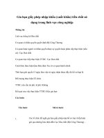
Typical applications using DSP techniques require at least the basic system
shown in Figure 3.1, consisting of an analog input and analog output. Along the
input path is an antialiasing filter for eliminating frequencies above the Nyquist
frequency, defined as one-half the sampling frequency. Otherwise, aliasing oc-
curs, in which case a signal with a frequency higher than one-half F
s
is dis-
guised as a signal with a lower frequency. The sampling theorem tells us that the
sampling frequency must be at least twice the highest frequency component f in
a signal, or
F
s
> 2f
Hence,
1/T
s
> 2(1/T)
where T
s
is the sampling period, or
(1/2)T > T
s
and
51
3
Input and Output with the DSK
Digital Signal Processing: Laboratory Experiments Using C and the TMS320C31 DSK
Rulph Chassaing
Copyright © 1999 John Wiley & Sons, Inc.
Print ISBN 0-471-29362-8 Electronic ISBN 0-471-20065-4
T
s
< (1/2)T
The sampling period T
s
must be less than one-half the period of the signal. For
example, if we assume that the ear cannot detect frequencies above 20 kHz, we
would sample a music signal at F
s
> 40 kHz (typically at 44.1 kHz or 48 kHz) in
order to remove frequency components higher than 20 kHz. We can then use a
lowpass input filter with a bandwidth or cutoff frequency at 20 kHz to avoid
aliasing.
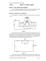
Figure 3.2 illustrates an aliased signal. Let the sampling frequency F
s
= 4
kHz, or a sampling period of T
s
= 0.25 ms. It is impossible to determine whether
it is the 5-kHz or the 1-kHz signal that is represented by the sequence (0, 1, 0,
–1). A 5-kHz signal will appear as a 1-kHz signal; hence, the 1-kHz signal is an
52
Input and Output with the DSK
FIGURE 3.1 DSP system with input and output.
FIGURE 3.2 Aliased sinusoidal waveform.
5 kHz
1 kHz
aliased signal. Similarly, a 9-kHz signal would also appear as a 1-kHz aliased
signal. We will verify this aliasing phenomenon with a programming example
in Section 3.4.
The A/D converts the input analog signal to a digital representation to be
processed by the digital signal processor. The maximum level of the input signal
to be converted is determined by the specific analog-to-digital converter
(ADC). Discrete levels or steps are used to represent the input signal. The num-
ber of steps is based on the range of the input-signal level and the number of
bits of the ADC. After the captured signal is processed, the result needs to be
sent to the outside world. Along the output path is a digital-to-analog converter
(DAC) that performs the reverse operation of the ADC, with different output
levels produced by the DAC based on its input. An output filter smooths out or
reconstructs the steps into an equivalent analog signal.
3.2 THE ANALOG INTERFACE CIRCUIT (AIC) CHIP
The DSK board includes an analog interface circuit (AIC) chip that connects to
the serial port on the C31. The AIC contains an ADC and a DAC as well as
switched-capacitor antialiasing input filter and reconstruction output filter, all
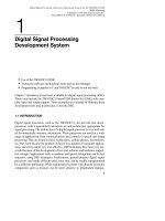
on a single C-MOS chip. Figure 3.3 shows the TLC32040 AIC functional block
diagram with two inputs, one output, 14-bit ADC and DAC, and input and out-
put filters. Programmable sampling rates with a maximum of 20 kHz for maxi-
3.2 The Analog Interface Circuit (AIC) Chip 53
FIGURE 3.3 TLC32040 AIC functional block diagram (reprinted by permission of Texas
Instruments).
mum performance are possible, although higher sampling rates for audio appli-
cations can be obtained, as described later.
The TLC32040 AIC is a member of the TLC3204x family of analog inter-
face circuit chips [1–5]. The evaluation module (EVM) contains the TLC32044
AIC, which has an input lowpass filter as well as a bypassable highpass input
filter in lieu of the bandpass input filter shown in Figure 3.3 [3].
The AIC primary input IN can be accessed from an RCA connector on the
DSK board. The AIC auxiliary input AUX IN is accessed through pin 3 from
the 32-pin connector JP3 along the edge of the DSK board. The input bandpass
filter is bypassable and can be programmed for a desired cutoff frequency or
bandwidth based on the sampling frequency. The output reconstruction lowpass
filter is fixed.
AIC Control
Data transmission occurs through the data receive (DR) and the data transmit
(DX) registers, two of the AIC’s serial port registers. The AIC is controlled
through the data transmit register. The two least significant bits (LSBs) are used
for communication functions. When the two LSBs are zeros, normal transmis-
sion occurs, and when they are ones, secondary communication takes place.
Secondary communication initializes and controls the AIC, allowing one sec-
ondary transmission before switching back. Figure 3.4 shows the AIC sec-
ondary communication protocol. Control functions are initiated by writing to
several of the AIC’s registers. Certain AIC specifications, such as input port and
input filter, are obtained using the control register. For example, as shown in
Figure 3.4, setting bit d2 and d4 to ones in the control register, inserts the AIC’s
input bandpass filter and enables the auxiliary input AUX IN, respectively.
Registers A and B on the AIC designate the location of control. The A regis-
ters consist of TA and RA and represent filter control, and the B registers consist
54
Input and Output with the DSK
FIGURE 3.4 AIC secondary communication protocol (reprinted by permission of Texas In-
struments).
of TB and RB registers and represent the A/D and D/A control. These registers
are associated with the AIC’s internal timing configuration [1]. The bit locations
for the transmit and receive registers TA and RA are:
bits 0–1 0,0
bits 2–6 RA
bits 7–8 don’t care (x)
bits 9–13 TA
bits 14–15 don’t care (x)
The bit locations for the transmit and receive registers TB and RB are:
bits 0–1 0,1
bits 2–7 RB
bit 8 don’t care (x)
bits 9–14 TB
bit 15 don’t care
The AIC can be configured for a specified sampling frequency and filter band-
width by requesting secondary communication and loading ones in the first two
LSBs. Secondary communication follows a primary communication that has
the two LSBs set to ones. The following sequence of data is loaded to the serial
port data transmit register and sets the two LSBs to one for each secondary
communication request:
a) 0x3 (or 3h) to request secondary communication
b) value for the A registers
c) 0x3 to request secondary communication again
d) value for the B registers
e) 0x3 to request secondary communication a third time
f) value to configure the control register
We can now proceed to find the A and B values in order to achieve a desired
sampling frequency and input filter bandwidth BW.
Calculating Values for A and B for a Desired F
s
and Filter BW
The C31 DSK has a 50-MHz input clock (CLKIN) that can generate a maxi-
mum timer frequency of MCLK = (CLKIN/4) = 12.5 MHz, which is above the
AIC’s maximum master clock frequency of 10 MHz specified for maximum
performance. The AIC master clock MCLK can be accessed and measured from
3.2 The Analog Interface Circuit (AIC) Chip 55
pin 8 on JP1 [4]. To achieve maximum performance with the AIC, we can di-
vide the input clock by 8, or
MCLK = CLKIN/8 = (50 MHz/8) = 6.25 MHz (3.1)
The switched-capacitor filter frequency (SCF) is related to the A transmit regis-
ter, or
SCF = MCLK/(2 × TA) (3.2)
and the sampling frequency is related to the transmit A and B registers, or
F
s
= MCLK/(2 × TA × TB) (3.3)
The input filter bandwidth or cutoff frequency is set at 3600 Hz for an SCF of
288 kHz [1]. A new SCF will result for a different BW. The following calcula-
tions illustrate the above and how to find the A and B values to set the AIC.
1. F
s
= 8 kHz (Desired)
The desired cutoff frequency of the input antialiasing filter is 3600 Hz for an
SCF of 288 kHz. From (3.2)
TA = MCLK/(2 × SCF) = 6.25 MHz/(2 × 288 kHz) = 10.85
Х 11 = (01011)
b
(3.4)
From (3.3)
TB = MCLK/(2 × TA × F
s
) = 6.25 MHz/(2 × 11 × 8,000) = 35.51
Х 36 = (100100)
b
From (3.4), the actual SCF is
SCF = 6.25 MHz/(2 × TA) = 284.09 kHz
The actual cutoff frequency or input filter bandwidth is shifted accordingly, or
BW = 3600(New SCF/Set SCF)
= 3600 (284.09 kHz/288 kHz) = 3551.14 Hz
The actual sampling frequency is then
F
s
= 6.25 MHz/(2 × TA × TB) = 6.25 MHz/(2 × 11 × 36) = 7891.41 Hz
56
Input and Output with the DSK
From Figure 3.4, using the bit locations for the control register, and setting TA =
RA, with 5 bits for TA, 6 bits for TB, and x for don’t care,
0 0 0 1 0 1 1 0 0 0 1 0 1 1 0 0 ⇒ 162Ch
x x | TA | x x | RA |
Separating the bits into nibbles or groups of four, A = 162Ch. Similarly, with
TB = RB
0 1 0 0 1 0 0 0 1 0 0 1 0 0 1 0 ⇒ 4892h
x | TB | x | RB |
B = 4892h. These values can be verified using a utility program AICCALC
included with the DSK software tools.
2. F
s
= 10 kHz (Desired)
Using the same cutoff frequency or BW for the input antialiasing filter as previ-
ously obtained with F
s
= 8 kHz, TA = 11. Then,
TB = 6.25 MHz/(2 × 11 × 10,000) = 28.41 Х 28 = (011100)
b
The actual sampling frequency is
F
s
= 6.25 MHz/(2 × TA × TB) = 6.25 MHz/(2 × 11 × 28) = 10,146 Hz
The B value is then
0 0 1 1 1 0 0 0 0 1 1 1 0 0 1 0 ⇒ 3872h
x | TB | x | RB |
or B = 3872h.
3. F
s
= 20 kHz (Desired)
Let BW = 8000 Hz (desired). Since the bandwidth is
BW = 3600(New SCF/Set SCF)
the new switched-capacitor filter frequency is
SCF = 8000(288 K)/3600 = 640 kHz
and the TA and TB register values are
3.2 The Analog Interface Circuit (AIC) Chip 57
TA = 6.25 MHz/(2 × 640 K) = 4.88 Х 5 = (00101)
b
TB = 6.25 MHz/(2 × 5 × 20000) = 31.25 Х 31 = (011111)
b
The actual SCF is
SCF = 6.25 MHz/(2 × 5) = 625 kHz
The actual bandwidth is
BW = 3,600(625 K/288 K) = 7812.5 Hz
The actual sampling frequency is
F
s
= 6.25 MHz/(2 × 5 × 31) = 20,161.29 Hz
The A value is then
0 0 0 0 1 0 1 0 0 0 0 1 0 1 0 0 ⇒ 0A14h
x x | TA | x x | RA |
or A = 0A14h and the B value is
0 0 1 1 1 1 1 0 0 1 1 1 1 1 1 0 ⇒ 3E7Eh
x | TB | x | RB |
or B = 3E7Eh. The A and B registers for four different sampling rates follow:
(Desired)F
s
, Hz (Actual) F
s
AB
8,000 7,891.41 0x162C 0x4892
10,000 10,146 0x162C 0x3872
16,000 15,943 0x0E1C 0x3872
20,000 20,161.29 0x0A14 0x3E7E
For F
s
= 16 kHz, the actual BW = 5580 Hz.
There is an additional set of registers TAЈ and RAЈ that can be used for
fine-tuning the sampling rate and filter bandwidth. In Section 3.4, we will set
the A and B values in the program examples in order to obtain a desired F
s
and
BW.
58
Input and Output with the DSK
3.3 INTERRUPTS AND PERIPHERALS
Interrupts
The TMS320C31 supports both internal and external interrupts that can inter-
rupt the CPU or the DMA, as well as a nonmaskable external reset interrupt [6].
Figure A.1 in Appendix A shows the global interrupt enable (GIE) bit register,
within the status register (ST), that controls all CPU interrupts. The GIE bit is
set to one to enable an interrupt. To disable an interrupt, disable the interrupt
enable (IE) register shown in Figure A.2 by setting it to zero, then set the GIE
bit also to zero. Figure A.3 shows the memory-mapped locations used for inter-
rupts [6].
Timers
The TMS320C31 supports two timers that can be used to count external events.
They provide the timing necessary to signal an ADC to start conversion. Figure
A.4 in Appendix A shows the peripheral bus memory-mapped registers. The
timer global control register (Figure A.5) at memory location 808020 monitors
the timer’s status, and the timer period register at the memory address 808028
specifies the timer’s frequency. The timer counter register at memory location
808024 contains the value of the incrementing counter. When the value of the
period register equals that of the timer counter register, the counter register re-
sets to zero. At reset, both the timer counter and the period registers are set to
zero. We will use these registers to set a desired interrupt rate, effectively
achieving a desired F
s
.
Programming examples will further illustrate the use of an interrupt generat-
ed internally with a timer. Section 8.4 describes a project to control the ampli-
tude of a generated sinewave using both internal and external interrupts.
Serial Port
The TMS320C31 supports one serial port (the C30 has two) with a set of con-
trol registers as shown in Figure A.4. Figure A.6 shows the serial port global
control register format. The AIC on board the DSK connects to the C31 serial
port, through a 22-pin connector jumper block JP1 that connects the C31
signals to the AIC. These jumpers can be removed to disconnect the on-
board AIC from the C31 and use JP1 to access the C31 signals and interface
to an external board. Appendix D describes a board that contains a CS4216
(or CS4218) 16-bit codec that interfaces to the C31 signals through the 22-pin
connector JP1.
3.3 Interrupts and Peripherals 59
AIC Data Configuration
The following registers are set in order to initialize the AIC:
Register Address Command
Timer 0 period 0x808028 Load 0x1
Timer 0 global control 0x808020 Load 0x3C1
I/O flag IOF Load 0x2
SP0 transmit port control 0x808042 Load 0x131
SP0 receive port control 0x808043 Load 0x131
SP0 global control 0x808040 Load 0x0E970300
SP0 data transmit 0x808048 Load 0x0
I/O IOF Load 0x6
Interrupt flag IF Load 0x0
Interrupt enable IE OR 0x10
Status register ST OR 0x2000
In the next section, we will illustrate how to configure the AIC through pro-
gramming examples.
3.4 PROGRAMMING EXAMPLES USING TMS320C3x
AND C CODE
Several programming examples using both assembly and C code illustrate inter-
rupts and I/O communications with the AIC. We developed a program in both
assembly and C that contains several routines to communicate with the AIC for
input and output. Such program can be used as an AIC “communication box.”
In Example 1.2, we generated a real-time sinusoid with the program
SINE4P.ASM. The program SINE4P.ASM “includes” the AIC communica-
tion program AICCOM31.ASM that contains the AIC routines for initialization
and input/output capabilities.
Example 3.1 Internal Interrupt Using TMS320C3x Code
Figure 3.5 shows a listing of the program INTERR.ASM that illustrates an in-
terrupt generated internally by the C31 timer 0. The rate at which an interrupt
occurs is determined without the use of the AIC. Consider the following from
the program.
1. The interrupt rate is determined by a value set in the period register, or
rate = 12.5 MHz/(2 × period)
2. The period register at the memory address 808028 and the global regis-
ter at the memory address 808020 are initialized. Bit 8 within the interrupt en-
able (IE) register TINT0 is enabled. Appendix A contains information on these
registers.
60
Input and Output with the DSK
3. Execution continues within a loop containing the two instructions WAIT
IDLE and BR WAIT until an interrupt occurs. The counter register at memory
address 808024 increments from 0, 1, , until it reaches the period value of
2000h set in the period register at which time an interrupt occurs. The counter
register is reset to zero and is incremented again.
3.4 Programming Examples Using TMS320C3x and C Code 61
;INTERR.ASM - DEMONSTRATES INTERNAL INTERRUPT WITHOUT THE AIC
.start “intsect”,0x809FC9 ;starting address for interrupt
.start “.text”,0x809A00 ;starting address for text
.start “.data”,0x809C00 ;starting address for data
.sect “intsect” ;section for interrupt
BR ISR ;interrupt vector TINT0
.data ;data section
PERIOD .word 2000H ;interrupt rate=12.5MHz/(2*PERIOD)
IE_REG .word 100H ;enable timer 0 (TINT0) for interrupt
PER_ADDR .word 808028H ;(TLCK0) period register location
TCNTL .word 2C1H ;control register value
ST_REG .word 2000H ;set status register
OUTPUT .word 0xA ;initial output value
OUT_ADDR .word 0x809A30 ;output address
STACKS .word 809F00h ;init stack pointer
.entry BEGIN ;start of code
.text ;assemble into text section
BEGIN LDP STACKS ;init data page
LDI @STACKS,SP ;SP -> 0809F00h
LDI @PER_ADDR,AR0 ;TINT0 period register =>AR0
LDI @OUT_ADDR,AR1 ;output address =>AR1
LDI @PERIOD,R0 ;period value => R0
STI R0,*AR0—(8) ;set TLCK0 period @ 808028H
LDI @TCNTL,R0 ;control register value =>R0
STI R0,*AR0 ;set TLCK0 global control @ 808020H
LDI @OUTPUT,R0 ;R0 = output value
OR @IE_REG,IE ;enable TINT0 interrupt bit 8
WAIT IDLE ;wait for interrupt
BR WAIT ;branch to WAIT until interrupt
; INTERRUPT VECTOR
ISR ADDI 2,R0 ;increment output value by 2
STI R0,*AR1++ ;store output value
RETI ;return from interrupt
.end ;end
FIGURE 3.5 Interrupt program using TMS320C3x code (INTERR.ASM).
4. On interrupt, execution proceeds to the interrupt service routine (ISR).
An initial value of 0xA = 10 (decimal) set as output is incremented by two
(within the interrupt service routine) and the result stored in memory location
809a30, the starting output address specified by OUT_ADDR.
5. Execution returns to the WAIT loop until the next interrupt occurs.
6. Run this program for one or two seconds, then stop/halt execution. Type
memd 0x809a30 to verify the output values 12, 14, 16, 18, The C31
should be reset first, before displaying the output values, if an old version of the
DSK tools is used.
Due to the interrupt structure, it is not possible to single-step and observe the
counter register at 808024 incrementing, or to observe the sequence of the
program counter PC illustrating the instruction to be executed next, specifically
when the timer counter register equals the period register value. A modified ver-
sion of this program can be single-stepped through using a simulator available
from Texas Instruments [3]. The simulator is a software program similar in
function to the debugger but which models and does not require the C31. With a
debugger, the executable file is downloaded into an actual C31 chip.
Example 3.2 Sine Generation with AIC Data Using
TMS320C3x Code
Figure 3.6 shows a listing of the program SINEALL.ASM that generates a sinu-
soid with four points in a look-up table and contains the necessary code to com-
municate with the AIC. This example can serve as a sample program that illus-
trates how to integrate AIC communication data directly within a specific
program.
Example 1.2 illustrates a sine generation program using a table look-up pro-
cedure with four points that calls the AIC routines included in a separate file
62
Input and Output with the DSK
FIGURE 3.6 Sine generation program with AIC data incorporated (SINEALL.ASM).
;SINEALL.ASM - GENERATES A SINE WITH 4 POINTS USING AIC POLLING
.start “.text”,0x809900 ;starting addr for code
.start “.data”,0x809c00 ;starting addr for data
.data ;data section
PBASE .word 808000h ;peripheral base address
SETSP .word 0E970300h ;serial port set-up data
ATABLE .word AICSEC ;SP0 AIC init table addr
AICSEC .word 162Ch,1h,4892h,67h ;Fs = 8 kHz
SINE_ADDR .word SINE_VAL ;address of sine values
.brstart “SINE_BUFF”,8 ;size of sine table
(continued on next page)
3.4 Programming Examples Using TMS320C3x and C Code 63
SINE_VAL .word 0,1000,0,-1000 ;sine values
LENGTH .set 4 ;length of circular buffer
.entry BEGIN ;start of code
.text ;assemble into text section
BEGIN LDP AICSEC ;init to data page 128
LDI @PBASE,AR0 ;AR0=peripheral base address
LDI 1h,R0 ;Timer CLK=H1/2*(AIC master CLK)
STI R0,*+AR0(28h) ;timer period reg(TCLK0=6.25MHZ)
LDI 03C1h,R0 ;to init timer global register
STI R0,*+AR0(20h) ;reset timer
LDI 62h,IOF ;AIC reset = 0
LDI @ATABLE,AR1 ;AR1=AIC init data
RPTS 99 ;repeat next instr 100 times
NOP ;keep IOF low for a while
LDI 131h,R0 ;X & R port control register data
STI R0,*+AR0(42h) ;FSX/DX/CLKX=SP operational pins
STI R0,*+AR0(43h) ;FSR/DR/CLKR=SP operational pins
LDI @SETSP,R0 ;RESET->SP:16 bits,ext clks,std mode
STI R0,*+AR0(40h) ;FSX=output & INT enable SP global reg
LDI 0,R0 ;R0=0
STI R0,*+AR0(48h) ;clear serial port XMIT register
OR 06h,IOF ;bring AIC out of reset
LDI 03h,RC ;RC=3 to transmit 4 values
RPTB SECEND ;repeat 4 data transmit of sec com
CALL TWAIT ;wait for data transmit
LDI 03h,R0 ;valuefor secondary XMIT request
STI R0,*+AR0(48h) ;secondary XMIT request to AIC
CALL TWAIT ;wait for data transmit
LDI *AR1++(1),R0 ;R0=next AIC data
SECEND STI R0,*+AR0(48h) ;DTR=curent AIC data
LDI LENGTH,BK ;BK=size of circular buffer
LDI @SINE_ADDR,AR1 ;AR1=address of sine values
LOOP LDI *AR1++%,R7 ;R7=table value
CALL TWAIT ;wait for data transmit
LSH 2,R7 ;Two LSB MUST = 0 for primary AIC com
STI R7,*+AR0(48h) ;DTR=next data for AIC D/A
BR LOOP ;branch back to LOOP
TWAIT LDI *+AR0(40h),R0 ;R0=content of SP global control reg
AND 02h,R0 ;see if transmit buffer is ready
BZ TWAIT ;if not ready, try again
RETS ;branch from subroutine
FIGURE 3.6 (continued)
AICCOM31.ASM. A C version of the AIC communication program is described
later. These routines enable the initialization of the AIC for input/output. While
it is more efficient to integrate these AIC routines within each specific program
for faster execution, it is more convenient to use these routines as a “black box,”
as was done in Example 1.2.
Appendix A describes a number of special registers on the C31 that are
available for communicating with the AIC. Assemble and run SINEALL.ASM
to verify a generated output sinusoid with a frequency of f = F
s
/4 = 2 kHz. Con-
sider the following from the program.
1. The values in AICSEC specify a sampling rate of 8 kHz with a band-
width of 3551 Hz. The DAC output rate is the same as the input ADC rate (no
input is used in this program example). The AIC master clock is set to 6.25
MHz with the instruction LDI 1,R0 with R0 stored in the timer-period regis-
ter. Example 1.2 illustrates how the AIC master clock can be changed with that
instruction. For example, a value of two in the timer-period register with LDI
2,R0 reduces the AIC master clock to 3.125 MHz, and effectively also reduces
the sampling rate by two. The AIC master clock frequency can be verified from
pin 8 on the DSK board connector JP1. Figure A.4 in Appendix A shows the
memory-mapped timer locations. The second value of 1h in AICSEC sets the
registers TAЈ and RAЈ on the AIC for fine-tuning the sampling frequency
(though not used).
2. The following registers are initialized: the global control register at mem-
ory location 808020 (using timer 0), the IOF register, the serial port control
registers at 808042 and 808043, the serial port global control register at
808040, and the data transmit register at 808048 (see Figures A4–A8).
3. By initializing the timer global control register with 0x3C1, bit 8 (C/P
ෆ
)
in Figure A.5 is set to one and the clock mode is chosen (not the pulse mode),
which allows for an external output of 50% duty cycle.
4. Request for secondary communication is made through the data transmit
register to transmit the four values set in AICSEC that specify a sampling rate
of 8 kHz, the filter’s BW, the AIC primary input IN, and the insertion of the
AIC input bandpass filter.
5. The sequence of four values represents a sine waveform, set in
SINE_VAL, and are then transmitted through the data transmit register at mem-
ory location 808048 (Figure A.4) through a polling procedure within the
TWAIT routine.
6. The IOF register is kept low for a while. The AIC reset pin is connected
to the C31 XF0 pin (see Figure A.8).
7. The serial port global control register is loaded with 0E970300 and
causes the following (Figures A.4 and A.6):
a. Configures FSX as input
b. Disables handshake mode
64
Input and Output with the DSK
c. Sets both transmit and receive sync pulses to variable rate
d. Sets both transmit and receive frame sync modes to standard mode
e. Sets all clocks and data interface pin polarities to active high
f. Sets all frame sync pulses to active low
g. Transfers 16-bit data
h. Disables all interrupts except the transmit interrupt
i. Starts serial port operations
j. Loads the data transmit register with an initial value of zero
8. Within the block of code or loop starting at the instruction RPTB
SECEND and ending at the label SECEND, the first three lines of code load the
data transmit register with the primary communication data for the AIC and the
subsequent three lines of code load the data transmit register with the secondary
communication data for the AIC.
9. The AIC will issue the transmit sync pulse to the C31 to start primary
communication. After the data is received, the AIC uses bits 2–15 as D/A data
and bits 0–1 as control data. Both control bits being set to 1 will cause the AIC
to issue another transmit sync pulse (four AIC shift clock cycles after the prima-
ry communication ends) to the C31 to start secondary communication. After the
secondary communication data is received, the AIC uses bits 0–1 to control the
register that will be loaded and bits 2–15 as the data that will be loaded in the
AIC register. The next data received by the AIC will be treated as primary com-
munication data. All primary communications are performed at an interval that
is determined by the A/D and D/A conversion rates.
10. The AIC is ready for transmission of a new word when bit 1 of the serial
port global control register XRDY is set to 1 (Figure A.6), otherwise wait.
Example 3.3 Loop/Echo with AIC Routines in Separate File,
Using TMS320C3x Code
This example illustrates input and output with the AIC and the effects of alias-
ing. Figure 3.7 shows a loop or echo program LOOP.ASM that “includes”
the program AICCOM31.ASM shown in Figure 3.8. This separate program
AICCOM31.ASM contains the AIC communication routines (see also
SINEALL.ASM). This program was introduced in Example 1.2 in Chapter 1. It
is instructive to read the comments in these programs. The program AIC-
COM31.ASM includes options to achieve a data conversion rate using either in-
terrupt or polling, and to access the primary and auxiliary inputs. Consider the
following.
1. The routine AICSET in AICCOM31.ASM is called to initialize the AIC,
followed by calling the routine AICIO_P for input and output using a polling
3.4 Programming Examples Using TMS320C3x and C Code 65
66
Input and Output with the DSK
;LOOP.ASM - LOOP PROGRAM. CALLS AIC ROUTINES IN AICCOM31.ASM
.start “.text”,0x809900 ;starting address for text
.start “.data”,0x809C00 ;starting address for data
.include “AICCOM31.ASM” ;AIC communication routines
.data ;data section
AICSEC .word 162Ch,1h,4892h,67h ;Fs = 8 kHz
.text ;text section
.entry BEGIN ;start of code
BEGIN LDP AICSEC ;init to data page 128
CALL AICSET ;init AIC
LOOP CALL AICIO_P ;R6 = input, R7 = output
LDI R6,R7 ;output R7=new input in R6
BR LOOP ;loop continuously
.end ;end
FIGURE 3.7 Loop/echo program using TMS320C3x code (LOOP.ASM).
FIGURE 3.8 AIC communication program (AICCOM31.ASM).
*AICCOM31.ASM - AIC COMMUNICATION ROUTINES - POLLING OR INTERRUPT
.data ;assemble into data section
PBASE .word 808000h ;peripheral base address
SETSP .word 0E970300h ;serial port set-up data
ATABLE .word AICSEC ;SP0 AIC init table address
.text ;assemble into text section
AICSET PUSH AR0 ;save AR0
PUSH AR1 ;save AR1
PUSH R0 ;save R0
PUSH R1 ;save R1
LDI @PBASE,AR0 ;AR0 -> 808000h
LDI 1,R0 ;timer CLK=H1/2*(AIC master CLK)
STI R0,*+AR0(28h) ;timer period reg(TCLK0=6.25 MHZ)
LDI 03C1h,R0 ;init timer global register
STI R0,*+AR0(20h) ;reset timer
LDI 62h,IOF ;AIC reset = 0
LDI @ATABLE,AR1 ;AR1 -> AIC init data
RPTS 99 ;repeat next instr 100 times
NOP ;keep IOF low for a while
LDI 131h,R0 ;X & R port control register data
STI R0,*+AR0(42h) ;FSX/DX/CLKX=SP operational pins
STI R0,*+AR0(43h) ;FSR/DR/CLKR=SP operational pins
(continued on next page)
3.4 Programming Examples Using TMS320C3x and C Code 67
LDI @SETSP,R0 ;RESET->SP:16 bits,ext clks,std mode
STI R0,*+AR0(40h) ;FSX=output&INT enable SP global reg
LDI 0,R0 ;R0 = 0
STI R0,*+AR0(48h) ;clear serial port XMIT register
OR 06h,IOF ;bring AIC out of reset
LDI 03h,RC ;RC=3 to transmit 4 values
RPTB SECEND ;repeat 4 data transmit of sec com
CALL TWAIT ;wait for data transmit
LDI 03h,R0 ;value for secondary XMIT request
STI R0,*+AR0(48h) ;secondary XMIT request to AIC
CALL TWAIT ;wait for data transmit
LDI *AR1++(1),R0 ;AR1 -> next AIC init data
SECEND STI R0,*+AR0(48h) ;DTR = current AIC data
POP R1 ;restore R1
POP R0 ;restore R0
POP AR1 ;restore AR1
POP AR0 ;restore AR0
RETS ;return from subroutine
AICSET_I ;—-CONFIG FOR INTERRUPT —————-
CALL AICSET ;call AICSET routine
LDI 0h,IF ;clear IF register
OR 10h,IE ;enable EXINT0 CPU interrupt
OR 2000h,ST ;global interrupt enable
RETS ;return from subroutine
;——————————TRANSMIT WAIT ROUTINE————————————-
TWAIT PUSH AR0 ;save AR0
PUSH R0 ;save R0
LDI @PBASE,AR0 ;AR0 -> 0808000h
TW1 LDI *+AR0(40h),R0 ;R0=content of SP global control reg
AND 02h,R0 ;see if transmit buffer is ready
BZ TW1 ;if not ready, try again
POP R0 ;restore R0
POP AR0 ;restore AR0
RETS ;return from subroutine
;——————————AIC TRANSFER ROUTINE—————————————
AICIO_I LDI R7,R6 ;copy output to modify for AIC
LSH 2,R6 ;two LSB must=0 for primary AIC comm
IO PUSH AR0 ;save AR0
LDI @PBASE,AR0 ;AR0 -> 0808000h
STI R6,*+AR0(48h) ;DTR = next data for AIC D/A
FIGURE 3.8 (continued)
(continued on next page)
procedure. The two extended-precision registers R6 and R7 are selected for in-
put and output, respectively.
2. Assemble LOOP.ASM (not AICCOM31.ASM) and run it. Apply a sinu-
soidal input with an amplitude between 1 and 3 V and a frequency between 500
and 3 kHz. Verify a delayed output signal of the same frequency as the input
signal.
3. To test the AIC auxiliary input AUX IN, change the fourth value in AIC-
68
Input and Output with the DSK
LDI *+AR0(4Ch),R6 ;R6 = DRR data from AIC A/D
LSH 16,R6 ;left shift for sign extension
ASH -18,R6 ;right shift keeping sign
POP AR0 ;restore AR0
RETS ;return from subroutine
;——————————AIC POLLING ROUTINE—————————————-
AICIO_P CALL TWAIT ;wait for data to be transferred
CALL AICIO_I ;call AIC transfer routine
RETS ;return from subroutine
SW_IO PUSH AR0 ;save AR0
LDI @PBASE,AR0 ;AR0 -> 0808000h
LDI R7,R6 ;copy output to modify for AIC
LSH 2,R6 ;prepare for secondary AIC com
OR 03h,R6 ;set two LSB for secondary com
CALL TWAIT ;wait for data to be transferred
CALL IO ;call AIC transfer routine
CALL TWAIT ;wait for data to be transferred
STI R1,*+AR0(48h) ;DTR = next data for AIC control
POP AR0 ;restore AR0
RETS ;return from subroutine
;SUBROUTINES FOR PRIMARY OR AUXILIARY INPUT
IOPRI PUSH R1 ;save R1
LDI 063h,R1 ;load secondary com data into R1
CALL SW_IO ;call IO routine to switch inputs
POP R1 ;restore R1
RETS ;return from subroutine
IOAUX PUSH R1 ;save R1
LDI 073h,R1 ;load secondary com data into R1
CALL SW_IO ;call IO routine to switch inputs
POP R1 ;restore R1
RETS ;return from subroutine
FIGURE 3.8 (continued)
SEC from 67h to 77h. This sets bit d4 to 1 (see Figure 3.4) and selects AUX
IN, available from pin 3 of the 32-pin edge connector JP3 on the DSK board.
Verify that the delayed output has the same frequency as the input but with an
amplitude reduced by two.
4. Verify that the primary input IN is available from pin 1 on JP3. Note that
bit d4 within the AIC control register in Figure 3.4 must be set to zero in order
to access the primary input.
5. Bits d6 and d7 in the AIC control register determine the gain control.
Change the fourth value 67h to 27h to set bits d6 and d7 to zero and verify that
the output amplitude is reduced by two. Change 67h to 0A7 to set bit d6 to zero
and bit d7 to one, and verify that the output amplitude is increased by two.
6. Bypass the AIC input bandpass filter with bit d2 in the AIC control regis-
ter set to zero by changing 67h to 63h in AICSEC. Increase the input signal
frequency to slightly above 4000 Hz. The output signal will appear as a signal
with a lower frequency, referred to as an aliased signal. The input bandpass fil-
ter on the AIC removes these imaging effects. The input filter is set with a band-
width less than the ideal Nyquist frequency, referred to as one-half the sampling
frequency. Increase the input signal frequency to approximately 5 kHz, then to 9
kHz and observe these imaging effects. An aliased signal is present at 3 kHz,
then at 1 kHz.
Example 3.4 Loop/Echo with Interrupt Using TMS320C3x Code
Figure 3.9 shows the loop or echo program LOOPI.ASM, which illustrates con-
version rate or sampling rate using interrupt. Consider the following.
1. An interrupt service routine with the label ISR is defined within the sec-
tion “intsect” which is at the address 809FC5. As shown in Figure A.3, inter-
rupt XINT0 is selected.
2. AICSET_I and AICIO_I initialize and invoke the AIC input and output
routines for interrupt. The IDLE instruction waits for an interrupt to occur. On
interrupt, execution proceeds to the interrupt service routine ISR. The AIC in-
put and output routines are then invoked with AICIO_I. Execution returns,
with the return from interrupt instruction RETI. The instruction LDI R6,R7
is then executed, which loads the input from R6 into R7 for output. The branch
instruction BR LOOP causes execution to return to the IDLE instruction and
wait for the next interrupt to occur.
3. The AIC input bandpass filter is bypassed by using 63h in lieu of 67h in
AICSEC with bit d2 = 0 in Figure 3.4. Input a sinusoidal signal and increase the
input frequency beyond 4 kHz. Observe the aliasing effects as you increase the
input signal frequency beyond the BW of the input filter on the AIC. Do you
observe an aliased 1-kHz signal when the input signal frequency is 9 kHz? See
also the previous loop program example, which uses a polling procedure to ob-
tain an output sample rate.
3.4 Programming Examples Using TMS320C3x and C Code 69
Example 3.5 Sine Generation with Interrupt Using
TMS320C3x Code
Figure 3.10 shows the program listing SINE8I.ASM, which is the interrupt-
driven version of SINE4P.ASM in Example 1.2 and uses eight points to gener-
ate a sinusoid. On interrupt, execution proceeds to the interrupt service routine
ISR. The first value (zero) contained in the memory address specified by AR1
is loaded into R7. When the AIC input/output routines are invoked, the output is
in R7. In this example, processing for input (using R6) is not necessary. The in-
struction RETI causes execution to return to the IDLE instruction either direct-
ly or after the BR WAIT instruction, and waits until the next interrupt occurs.
Run this program and verify that it generates an output sinusoid with a fre-
quency of f = 1 kHz, the ratio of the sampling rate and the number of points. An
FM signal can be implemented based on the program SINE8I.ASM. See Ex-
periment 3 in Section 3.7.
Example 3.6 Pseudorandom Noise Generation Using
TMS320C3x Code
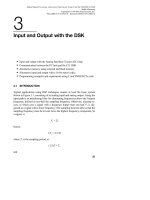
A 32-bit random noise sequence is generated using the following scheme shown
in Figure 3.11:
a) A 32-bit seed or initial value is chosen (for example, 7E521603h).
70
Input and Output with the DSK
FIGURE 3.9 Loop/echo program with interrupt (LOOPI.ASM).
;LOOPI.ASM - LOOP PROGRAM USING INTERRUPT
.start “intsect”,0x809FC5 ;starting address for interrupt
.start “.text”,0x809900 ;starting address for text
.start “.data”,0x809C00 ;starting address for data
.include “AICCOM31.ASM” ;AIC communication routines
.sect “intsect” ;section for interrupt vector
BR ISR ;XINT0 interrupt vector
.data ;data section
AICSEC .word 162Ch,1h,4892h,63h ;Fs = 8 kHz
.entry BEGIN ;start of code
.text ;text section
BEGIN LDP AICSEC ;init to data page 128
CALL AICSET_I ;init AIC
LOOP IDLE ;wait for transmit interrupt
LDI R6,R7 ;output R7=new input in R6
BR LOOP ;branch back to LOOP
ISR CALL AICIO_I ;output R7, R6=input
RETI ;return from interrupt
;SINE8I.ASM - GENERATES A SINE WITH 8 POINTS USING INTERRUPTS
.start “intsect”,0x809FC5 ;starting addr for interrupt
.start “.text”,0x809900 ;starting address for text
.start “.data”,0x809C00 ;starting address for data
.include “AICCOM31.ASM” ;AIC communication routines
.sect “intsect” ;section for interrupt vector
BR ISR ;XINT0 interrupt vector
.data ;data section
AICSEC .word 162Ch,1h,4892h,67h ;Fs = 8 kHz
SINE_ADDR .word SINE_VAL ;starting addr of sine values
.brstart “SINE_BUFF”,16 ;align sine table
SINE_VAL .word 0,707,1000,707,0,-707,-1000,-707 ;sine values
LENGTH .set 8 ;length of circular buffer
.entry BEGIN ;start of code
.text ;text section
BEGIN LDP AICSEC ;init to data page 128
CALL AICSET_I ;init AIC
LDI LENGTH,BK ;BK=size of circular buffer
LDI @SINE_ADDR,AR1 ;AR1=starting addr of sine values
WAIT IDLE ;wait for interrupt
BR WAIT ;branch to wait until interrupt
; INTERRUPT SERVICE ROUTINE
ISR LDI *AR1++%,R7 ;R7=sine value for output
CALL AICIO_I ;call AIC for output
RETI ;return from interrupt
FIGURE 3.10 Sine generation program with interrupt (SINE8I.ASM).
FIGURE 3.11 Pseudorandom noise generator diagram.
71
b) A modulo 2 sum of bits 17, 28, 30, and 31 is performed.
c) The LSB of the result (0 or 1) is tested and scaled to a positive or to a neg-
ative value.
d) The seed value is shifted left by one and the previous resulting bit is
placed in the LSB position and the process repeated.
Figure 3.12 shows the program listing PRNOISE.ASM that generates a
72
Input and Output with the DSK
;PRNOISE.ASM - PSEUDORANDOM NOISE GENERATOR
.start “.text”,0x809900 ;starting address of text
.start “.data”,0x809C00 ;starting address of data
.include “AICCOM31.ASM” ;AIC communication routines
.data ;data section
AICSEC .word 162Ch,1h,4892h,67h ;Fs = 8 kHz
SEED .word 7E521603h ;initial seed value
PLUS .word 400h ;positive level
MINUS .word 0FFFFFC00h ;negative level
.entry BEGIN ;start of code
.text ;text section
BEGIN LDP AICSEC ;init to data page 128
CALL AICSET ;initialize AIC
LDI @SEED,R0 ;R0 =initial seed value
LOOP LDI R0,R4 ;put seed in R4
LSH -31,R4 ;move bit 31 to LSB =>R4
LDI R0,R2 ;R2 = R0 = SEED
LSH -30,R2 ;move bit 30 to LSB =>R2
ADDI R2,R4 ;add bits (31+30) =>R4
LDI R0,R2 ;R2 = R0 = SEED
LSH -28,R2 ;move bit 28 to LSB =>R2
ADDI R2,R4 ;add bits (31+30+28) =>R4
LDI R0,R2 ;R2 = R0 = SEED
LSH -17,R2 ;move bit 17 to LSB =>R2
ADDI R2,R4 ;add bits(31+30+28+17)=>R4
AND 1,R4 ;mask LSB of R4
LDIZ @MINUS,R7 ;if R4=0, R7 = MINUS value
LDINZ @PLUS,R7 ;if R4=1, R7 = PLUS value
LSH 1,R0 ;shift new seed left by 1
OR R4,R0 ;put R4 into LSB of R0
CALL AICIO_P ;output in R7 using AIC routine
BR LOOP ;repeat for next noise sample
FIGURE 3.12 Pseudorandom noise generation program (PRNOISE.ASM).
pseudorandom noise, with the output rate of each noise sample determined by
polling. Note the following from Figure 3.12.
1. The output sequence is scaled by 400h or by 0FFFFFC00h, defined in
PLUS or MINUS in the program, which correspond to ±1024.
2. The instruction LSH -31,R4 is a logical shift and is to the right (with
the minus), which brings bit 31 of the seed value into the LSB location. The se-
lected bits are first moved into the LSB location before being summed.
3. Assemble and run this program. Connect the output to a spectrum analyz-
er. The shareware utility Goldwave (see Section 1.4 and Appendix B) requires a
PC and a sound card to turn Goldwave into a virtual instrument as a spectrum
analyzer. The output appears flat (with averaging) and rolls off at approximately
3550 Hz, the AIC input filter bandwidth.
4. The amplitude level of the noise spectrum is determined by the PLUS and
MINUS scaling factors. Change PLUS and MINUS to 1000h and
0FFFFF000h, respectively, which correspond to ±4096 and verify that the am-
plitude spectrum is higher.
In Chapter 4, we will generate the output random noise (internally) as an in-
put to a filter so that we can observe the characteristics and frequency response
of the filter on a spectrum analyzer.
Example 3.7 Alternative Pseudorandom Noise Generation with
Interrupt Using TMS320C3x Code
Figure 3.13 shows the interrupt-driven program PRNOISEI.ASM that gener-
ates the same output noise as in the previous example. Consider the following.
1. Shifting the seed value 17 locations to the right moves bit 17 to the LSB
position. When the seed value is again shifted by 11, this places bit 28 into the
LSB location (having already been shifted by 17). In the previous example, the
original seed value is reloaded each time before it is shifted, whereas in this ex-
ample it is not.
2. On interrupt, execution proceeds to the interrupt vector address or service
routine specified by ISR, where each generated output sample is determined by
the interrupt rate or sampling rate (even though there is no input).
3. Before the procedure for generating each noise sample is repeated, the
seed value is shifted left by one, and the resulting bit (0 or 1) in R4 is placed in
the LSB position of R0, which now contains the new seed value (shifted by
one). After each noise sample, program execution returns to the IDLE instruc-
tion, either directly or first through the BR WAIT instruction to wait for the
next interrupt to occur, and then the interrupt service routine is repeated.
4. Verify the same type of output noise as in the previous example. Use a
larger sampling rate such as 20 kHz in order to obtain a wider spectrum before
it rolls off. For a sampling rate of 20 kHz, the A and B registers were calculated
previously in Section 3.2, where A = 0x0A14 and B = 0x3E7E.
3.4 Programming Examples Using TMS320C3x and C Code 73
74
Input and Output with the DSK
;PRNOISEI.ASM - ALTERNATIVE NOISE GENERATOR USING INTERRUPT
.start “intsect”,0x809FC5 ;starting address for interrupt
.start “.text”,0x809900 ;starting address for text
.start “.data”,0x809C00 ;starting address for data
.include “AICCOM31.ASM” ;AIC communication routines
.sect “intsect” ;interrupt vector section
BR ISR ;XINT0 interrupt vector
.data ;data section
AICSEC .word 162Ch,1h,4892h,67h ;Fs = 8 kHz
SEED .word 7E521603H ;initial seed value
PLUS .word 1000h ;positive noise level
MINUS .word 0FFFFF000H ;negative noise level
.entry BEGIN ;start of code
.text ;text section
BEGIN LDP AICSEC ;init to data page 128
LDI @SEED,R0 ;R0=initial seed value
LDI 0,R7 ;init R7 (output) tO 0
CALL AICSET_I ;initialize AIC
WAIT IDLE ;wait for interrupt
BR WAIT ;branch to WAIT
; INTERRUPT SERVICE ROUTINE
ISR LDI 0,R4 ;init R4=0
LDI R0,R2 ;put seed in R2
LSH -17,R2 ;move bit 17 TO LSB =>R2
ADDI R2,R4 ;add bit (17) =>R4
LSH -11,R2 ;move bit 28 to LSB =>R2
ADDI R2,R4 ;add bits (28+17) =>R4
LSH -2,R2 ;bit 30 (17+11+2)to LSB=>R2
ADDI R2,R4 ;add bits (30+28+17) =>R4
LSH -1,R2 ;move bit 31 to LSB =>R2
ADDI R2,R4 ;add bits (31+30+28+17)=>R4
AND 1,R4 ;mask LSB of R4
LDIZ @MINUS,R7 ;if R4 = 0, R7 = MINUS
LDINZ @PLUS,R7 ;if R4 = 1, R7 = PLUS
LSH 1,R0 ;shift new seed left by 1
OR R4,R0 ;put R4 into LSB of R0
CALL AICIO_I ;call AIC for output in R7
RETI ;return from interrupt
FIGURE 3.13 Alternative pseudorandom noise generation program with interrupt
(PRNOISEI.ASM).
Example 3.8 Loop/Echo with AIC Data Using C Code
Figure 3.14 shows a listing of the program LOOPALL.C, which incorporates
the AIC data for initialization and input/output communication using polling
(see also the program SINEALL.ASM in Example 3.2). It can serve as a sample
program that contains the code necessary to communicate with the AIC. The ex-
ecutable file LOOPALL.OUT is on disk and can be downloaded and run on the
DSK. Chapter 1 describes the use of the optional tools for compiling and link-
ing C-coded programs. Consider the following.
1. In certain situations, the optimizing C compiler reduces a repetitive state-
ment with a variable that changes as a result of an external event such as an in-
terrupt service routine to a single read statement. To prevent this, the volatile
declaration in the program tells the compiler not to optimize, for example, any
references to BPASE (Figure 3.14), since it is pointing at a peripheral address
808000. We use volatile int *PBASE as a pointer to that memory address.
2. Setting the timer period register to 1 at 808028 produces an output clock
frequency of 6.25 MHz, which can be verified from pin 8 on the DSK board
connector JP1.
3. When the UPDATE_SAMPLE function is called, an output occurs from
the data transmit register at 808048. This output is first shifted left by two to
enable primary AIC communication. Before each output and input, the transmit
buffer is first cleared. An input sample is obtained from the data receive register
at memory location 80804C. The input sample is sign-extended by first shift-
ing the data left by 16 bits and then right by 18 bits. Note that the AIC has a 14-
bit ADC and DAC.
In the next example, we will show a smaller program calling the AIC rou-
tines contained in a separate file.
The executable COFF file is on the accompanying disk. Input a sinusoidal
signal with a frequency between 1 and 3 kHz and an amplitude between 1 and 3
V, and verify the same result as with the loop programs implemented in C3x
code in Examples 3.3 and 3.4. Change the timer period register to double the
AIC master clock to 12.5 MHz. This effectively doubles the sampling frequency
or output rate and increases the bandwidth of the input filter on the AIC.
Example 3.9 Loop/Echo Calling AIC Routines in Separate File,
Using C Code
Figure 3.15 shows a listing of the program LOOPC.C that calls the AIC com-
munication routines contained in the program AICCOMC.C shown in Figure
3.16.
Verify the same result as in Examples 3.3, 3.4, and 3.8 yielding a delayed
output sinusoid with the same frequency as an input sinusoid.
3.4 Programming Examples Using TMS320C3x and C Code 75