Tài liệu 05 Analog-to-Digital Conversion Architectures docx
Bạn đang xem bản rút gọn của tài liệu. Xem và tải ngay bản đầy đủ của tài liệu tại đây (277.77 KB, 16 trang )
Kosonocky, S. & Xiao, P. “Analog-to-Digital Conversion Architectures”
Digital Signal Processing Handbook
Ed. Vijay K. Madisetti and Douglas B. Williams
Boca Raton: CRC Press LLC, 1999
c
1999byCRCPressLLC
5
Analog-to-Digital Conversion
Architectures
Stephen Kosonocky
IBM Corporation
T.J. Watson Research Center
Peter Xiao
NeoParadigm Labs, Inc.
5.1 Introduction
5.2 Fundamentals of A/Dand D/A Conversion
Nonideal A/D and D/A Converters
5.3 Digital-to-Analog Converter Architecture
5.4 Analog-to-Digital Converter Architectures
Flash A/D
•
Successive Approximation A/D Converter
•
Pipelined A/D Converter
•
Cyclic A/D Converter
5.5 Delta-Sigma Oversampling Converter
Delta-Sigma A/D Converter Architecture
References
5.1 Introduction
Digital signal processing methods fundamentally require that signals are quantized at discrete time
instancesandrepresentedasasequenceofwordsconsistingof1’sand0’s. Innature,signalsareusually
nonquantizedandcontinuouslyvariedwithtime. Naturalsignalssuchasairpressurewavesasaresult
of speech are converted by a transducer to a proportional analog electrical signal. Consequently, it
is necessary to perform a conversion of the analog electrical signal to a digital representation or v ice
versa if an analog output is desired. The number of quantization levels used to represent the analog
signal and the rate at which it is sampled is a function of the desired accuracy, bandwidth that is
required,andthecost ofthesystem. Figure5.1showsthebasicelementsofadigitalsignalprocessing
system. The analogsignalisfirstconvertedtoadiscretetimesignalbyasampleandhold circuit. The
FIGURE 5.1: Digital signal processing system.
output of the sample and hold is then applied to an analog-to-digital converter (A/D) circuit where
thesampledanalogsignal is convertedtoadigitallycodedsignal. The digital signalisthenappliedto
c
1999 by CRC Press LLC
thedigitalsignalprocessing(DSP)systemwherethedesiredDSPalgorithmisperformed. Depending
on the application, the output of the DSP system can be used directly in digital form or converted
back to an analog signal by a digital-to-analog converter (D/A). A digital filtering application may
produce an analog signal as its output, whereas a speech recognition system may pass the digital
output of the DSP system to a computer system for further processing. This section will describe
basic converter terminology and a sample of common architectures for both conventional Nyquist
rate converters and oversampled delta-sigma converters.
5.2 Fundamentals of A/D and D/A Conversion
The analog signal can be given as either a voltage signal or current signal, depending on the signal
source. Figure 5.2 shows the ideal transfer characteristics for a 3-bit A/D conversion. The output of
FIGURE 5.2: Ideal transfer characteristics for an A/D converter.
theconverterisann-bit digital code given as,
D =
A
sig
FS
=
b
n
2
n
+
b
n−1
2
n−1
+ +
b
1
2
1
(5.1)
where A
sig
is the analog signal, FS is the analog full scale level, and b
n
is a digital value of either
0 or 1. As shown in the figure, each digital code represents a quantized analog level. The width
of the quantized region is one least-significant bit (LSB) and the ideal response line passes through
the center of each quantized region. T he converse D/A operation can be represented as viewing the
digital code in Fig. 5.2 as the input and the analog signal as the output. An n-bit D/A converter
transfer equation is given as
A
sig
= FS
b
n
2
n
+
b
n−1
2
n−1
+ +
b
1
2
1
(5.2)
whereA
sig
is the analog output signal, FS isthe analog full scale level and b
n
is a binary coefficient.
The resolution of a converter is defined as the smallest distinct change that can be resolved (pro-
c
1999 by CRC Press LLC
duced) at an analog input (output) for an A/D (D/A) converter. This can be expressed as
A
sig
=
FS
2
N
(5.3)
where A
sig
is the smallest reproducible analog signal for an N-bit converter with full scale analog
signal of FS.
Theaccuracyofaconve rter,oftenreferredtoalsoasrelativeaccuracy,istheworst-caseerrorbetween
the actual and the ideal converter output after gain and offset errors are removed [1]. This can be
quantified as the number of equivalent bits of resolution or as a fraction of an LSB.
The conversion rate specifies the rate at which a digital code (analog signal) can be accurately
convertedintoananalogsignal(digitalcode). Accuracyisoftenexpressedasafunctionofconversion
rate and the two areclosely linked. The conversion rate is often an underlying factor in choosing the
converter architecture. The speed and accuracyofanalogcomponentsare a limiting factor. Sensitive
analogoperationscaneither bedoneinparallel,attheexpenseofaccuracy,orcycliclyreusedtoallow
high accuracy with lower conversion speeds.
5.2.1 Nonideal A/D and D/A Converters
Actual A/D and D/A converters exhibit deviations from the ideal characteristics shown in Fig. 5.2.
Integration of a complete converter on a single monolithic circuit or as a macro within a very large
scale integration (VLSI) DSP system presents formidable design challenges. Converter architectures
and design trade-offs are most often dictated by the fabrication process and available device types.
Device parameters such as voltage threshold, physical dimensions, etc. vary across a semiconductor
die. These variations can manifest themselves into errors. The following terms are used to describe
converter nonideal behavior:
1. Offset error, describedinFig.5.3,isad.c. errorbetweentheactualresponsewiththeideal
response. This can usually be removed by trimming techniques.
FIGURE 5.3: Offset error.
2. Gain errorisdefinedasanerrorintheslopeofthetransfercharacteristicshowninFig.5.4,
which can also usually be removed by trimming techniques.
c
1999 by CRC Press LLC
FIGURE 5.4: Gain error.
3. Integral nonlinearity is the measure of worst-case deviation from an ideal line drawn
between the full scale analog signal and zero. This is shown in Fig. 5.5 as a monotonic
nonlinearity.
FIGURE 5.5: Monotonic nonlinearity.
4. Differential nonlinearity is the measure of nonuniform step sizes between adjacent steps
in a converter. This is usually specified as a fraction of an LSB.
5. Monotonicityinaconverterspecifiesthattheoutputwillincreasewithanincreasinginput.
Certainconverterarchitecturescanguaranteemonotonicityforaspecifiednumberofbits
of resolution. A nonmonotonic transfer characteristic is detailed in Fig. 5.6.
6. Settling time for D/A convertersrefers to the time takenfrom a change of the digital code
to the point at which the analog output settles within some tolerance around the final
value.
c
1999 by CRC Press LLC
FIGURE 5.6: Nonmonotonic nonlinearity.
7. Glitches can occur during changes in the output at major transitions, i.e., at 1 MSB, 1/2
MSB,1/4MSB.Duringlargechanges,switchingtimedelaysbetweeninternalsignalpaths
can cause a spike in the output.
The choice of converter architecture can greatly affect the relative weight of each of these errors.
Data converters are often designed for low cost implementation in standard digital processes, i.e.,
digital CMOS, which often do not have well-controlled resistors or capacitors. Absolute values of
these devices can vary by as much as ± 20% under typical process tolerances. Post-fabrication
trimming techniques can be used to compensate for process variations, but at the expense of added
costandcomplexitytothemanufacturingprocess. Aswillbeshown,variousarchitecturaltechniques
can be used to allow high speed or highly accurate data conversion with such variations of process
parameters.
5.3 Digital-to-Analog Converter Architecture
The digital-to-analog (D/A) converter, also known as a DAC, decodes a digital word into a discrete
analog level. Depending on the application, this can be either a voltage or current. Figure 5.7 shows
a hig h level block diagram of a D/A converter. A binary word is latched and decoded and drivesa set
of switches that control a scaling network. A basic analog scaling network can be based on voltage
scaling, current scaling, or charge scaling [1, 2]. The scaling network scales the appropriate analog
level from the analog reference circuit and applies it to the output driver. A simple serial string of
identical resistors between a reference voltage and ground can be used as a voltage scaling network.
Switches can be used to tap voltages off the resistors and apply them to the output driver. Current
scaling approaches are based on sw itched scaled cur rent sources. Charge scaling is achieved by
applying a referencevoltagetoacapacitordivider using scaled capacitorswherethetotalcapacitance
value is determined by the digital code [1]. Choice of the architecture depends on the available
components in the target technology, conversion rate, and resolution. Detailed description of these
trade-offs and designs can be found in the references [1]–[5].
c
1999 by CRC Press LLC
5.4 Analog-to-Digital Converter Architectures
Theanalog-to-digital(A/D)converter,alsoknown asanADC,encodesananalogsignalintoadigital
word. Conventionalconverterswork bysamplingthe timevaryinganalogsignalat asufficientrateto
fully resolve the highest frequency components. According to the sampling theorem, the minimum
sampling rate is twice the frequency of the highest frequency contained in the signal source. The
samplingraterequirementthusbecomesthemajordeterministicfactorinchoosingaproperconverter
architecture. Certain architectures exploit parallelism to achieve high speed operation on the order
of 100’s of MHz, and others which can be used for high accuracy 16-bit resolution for signals with
maximum frequencies on the order of 10’s of KHz.
5.4.1 Flash A/D
TheflashA/D,alsoknownasaparallelA/D,isthehighestspeedarchitectureforA/Dconversionsince
maximumparallelismisused. Figure5.8showsablockdiagramofa3-bitflashA/Dconverter. Aflash
converter requires 2
n
− 1 analog comparators, 2
n
− 1 reference voltages, and a digital encoder. The
reference voltages are required to be evenly space d between 0.5 LSB above the most negative signal
and 1.5 LSB below the most positive signal and spaced 1 LSB apart. Each referencevoltageis applied
to the negative input of a comparator and the analog signal voltage is applied simultaneously to all
the comparators. A thermometer code results at the output of the comparators which is converted
toa digital wordbyencodinglogic. The speed of the converter is limited by the time delay through a
comparatorand the encoding logic. This speed is gained at the expense of accuracy, which is limited
bytheabilitytogenerateevenlyspacedreferencevoltagesandtheprecisionofthecomparators. Each
analog comparator must be precisely matched in order to achieve acceptableperformance at a given
resolution. For these reasons, flash A/D converters are typically used only for very hig h speed low
resolution applications.
5.4.2 Successive Approximation A/D Converter
AsuccessiveapproximationA/DconverterisformedcreatingafeedbacklooparoundaD/Aconverter.
Figure 5.9 shows a block diagram for an 8-bit successive approximation A/D. The operation of the
converter works by initializing the successive approximation register (SAR) to a value where all bits
aresetto0excepttheMSBwhichissetto1. This representsthe mid-levelvalue. The analog signal is
applied to a sample-and-hold (S/H) circuit, and on the first clock cycle the DAC converts the digital
code stored in the SAR into an analog signal. The comparator is used to determine whether the
analog signal is greater or less than the mid level, and control logic determines whether to leave the
MSB set to 1 or to change it back to 0. The process is repeated on the next clock cycle, but instead
the next MSB is tested. For an n-bit converter n clock cycles are required to fully quantize each
sample-and-hold signal. The speed of the successive approximation converter is largely limited by
the speed of the DAC and the time delay through the comparator. This type of converter is widely
used for medium speed and medium accuracy applications. The resolution is limited by the DAC
converter and the comparator.
5.4.3 Pipelined A/D Converter
A pipelined A/D converter achieves high-speed conversion and high accuracy at the expense of
latency in the conversion process. A pipelined A/D converter block diagram is shown in Fig. 5.10.
The conversion process is broken into multiple stages where, at each stage, a partial conversion is
done and the converted bits are shifted down the pipeline in digital registers. Figure 5.11 shows
the detail of a single pipeline stage. The analog signal is applied to a sample-and-hold circuit and
c
1999 by CRC Press LLC
FIGURE 5.7: Basic D/A converter block diagram.
FIGURE 5.8: 3-bit flash A/D converter.
c
1999 by CRC Press LLC
FIGURE 5.9: 8-bit successive approximation A/D converter.
FIGURE 5.10: Pipelined A/D converter.
the output is applied to an n-bit flash ADC where n is less then the total desired resolution. The
outputs of the ADC are connected directly to a DAC, and the output of the DAC is subtracted from
the original analog signal stored in the S/H to produce a residual signal. The residual sig nal is then
amplifiedby2
n
sothatitwillvarywithintheentirefullscalerangeofthenext stageandistransferred
on the next clock cycle. At this point the first stage begins conversion on the next analog sample.
The maximum conversion rate is determined by the time delay through a single stage. Pipelining
allows high resolution conversion without the need for many comparators. An 8-bit converter can
be ideally constructed with k = 4 stages with n = 2 bits of resolution per stage, requiring only 12
total comparators. This can be contrasted with an 8-bit flash converter requiring 255 comparators.
Each pipeline stage adds an additional cycle of latency before the final code is converted. Pipelined
converters also accommodate digital correction schemes for errors generated in the analog circuitry.
Digital correction can be achieved by using higher resolution ADC and DAC circuits in each stage
than required so that errors in the preceding stage can be detected and corrected digitally [5]. Auto
calibrationcanalsobeachievedbyaddingadditionalstagesaftertherequiredstagestoconverterrors
in the DAC values and storing these digitally to be added to the final result [6].
5.4.4 Cyclic A/D Converter
Cyclic A/D converters, also known as algorithmic converters, trade off conversion speed for high
accuracy without the need for calibration or device trimming. Figure5.12 shows a block diagram of
a cyclic A/D converter [5]. Here the same analog components are cyclicly reused for conversion of
each bit for each analog sample. The conversion processworks by initially sampling the input signal
bysettingswitchS1appropriately. Thesampledsignalisthenamplifiedbyafactoroftwoandapplied
c
1999 by CRC Press LLC
FIGURE 5.11: Diagram of single pipelined A/D converter stage.
to a comparator where it is compared to a reference level, Vref. If the voltage exceeds the reference
level, a bit value of 1 is produced and the referencevoltageis subtr acted from the amplified signal by
controlofswitchS2toproducetheresidualvoltageV
e
. Iftheamplifiedsignalislessthanthereference
voltage,Vref,the comparator outputs a 0, and V
e
representstheunchanged amplified signal. On the
remainingcyclesforthesample,switchS1changessothattheresidualvoltageV
e
isappliedtotheS/H
circuit. The cycle is repeated for each remaining bit. Operation on the conversion process produces
a serial stream of digital bit values from output of the comparator. An n-bit converter requires n
conversion cycles for each sampled signal.
FIGURE 5.12: Block diagram of a cyclic A/D converter.
5.5 Delta-Sigma Oversampling Converter
The oversampling delta-sigma A/D converter was first proposed 30 years ago [7], while it only
became popular after the matur ity of the VLSI digital technology. With the advancement of semi-
conductor technology, an increasing portion of signal processing tasks have been shifted from the
usualanalogdomaintodigitaldomain. Fordigitalsystemstointeractwithanalogsignalsources,such
as voice, data, and video, the role of analog-to-digital interface is essential. In voice data processing
and communication, an accurate digital form is often desired to represent the voice. Due to the
large demand of these systems, the cost must be kept at a minimum. All these requirements call
upon a need to implement monolithic high resolution analog-to-digital interfaces in economical
semiconductor technology. However, with the increasing complexity of integration and a trend
of reducing supply voltage, the accuracy of device components and analog signal dynamic r ange
c
1999 by CRC Press LLC
deteriorate. It becomesmoredifficulttorealizehigh resolutionconversionsbyconventional Nyquist
rate converter architecture.
Comparedto Nyquist rate converters, the oversamplingconverters use coarse analog components
at the front end and employ more digital signal processing in the later stages. High resolution
conversions areachievedbytradingoffspeedanddigitalsignal processingcomplexity, both ofwhich
can be easily realized in modern VLSI technology.
TheoversamplingA/DconverterandNyquistrateconverterarecomparedinFig.5.13. Anonover-
sampled A/D converter has an anti-aliasing lowpass filter in the front. The anti-aliasing filter atten-
uates high-frequency components buried in the analog input and prevents them from being aliased
into the signal frequency band. Because the converter is sampled at the Nyquist rate, which is twice
the input signal bandwidth, the anti-aliasing filter’s transition band must be very narrow and its
stop-band must have enough suppression of the out-of-band noise. This requirement makes the
filter very complex and adds to the complexity that a nonoversampled A/D already has.
FIGURE 5.13: (a) Nonoversampled A/D converter. (b) oversampled A/D converter.
Incomparison,anoversampleddelta-sigmaA/Dconverter,asshowninFig.5.13(b),issampledata
higherratethantheinputNyquistrate. Asimplefirst-orderlowpassfilterissufficienttoattenuatethe
noise components at the sampling frequency re gion to avoid the noisealiasing. This is becauseonly
the noise components close to the sampling frequency can be aliased back into the signal band. This
arrangementsimplifiesthedesignandimplementationofthefilter. ThecomplexityoftheA/Ditselfis
muchsimplerthanthenonoversampledA/Dconvertersaswewillseelater. Theonlyextracomplexit y
in the oversampled A/D converters is that more digital signal processing is required after the A/D
conversion. But this becomes less and less an issue with the advancement of the VLSI technology.
In the following sections, we will explain the conversion principle and various architectures of the
oversampling delta-sigma converter.
5.5.1 Delta-Sigma A/D Converter Architecture
Delta-Sigma Oversampling A/D Conver ter Principle
The structure of a first-order delta-sigma converter is shown in Fig. 5.14. The input signal is
c
1999 by CRC Press LLC
FIGURE 5.14: The modulator of a first-order delta-sigma converter. T is the sampling period and n
is the index.
sampled at a frequency f
s
(T = 1/f
s
). A feedback signal from a 1-bit D/A converter is subtracted
from the input and the residue signal is accumulated by an integrator. The output of the integrator
is quantized to generate a 1-bit digital stream. This digital output sets the sign of the feedback. If
the digital output is 1, it feeds back a large negative signal to subtract from the input signal. The
net effect of the feedback loop is to keep the output of the integrator small so that the output digits
always track the amplitudes of the input signal.
The resolution of an A/D converter is determined by the quantization noise generated in the
process. Even though a delta-sigma converter only has an 1-bit quantizer, much higher resolution is
achieved by employing the noise shaping mechanism to move the noise out of the signal band and
later blocking it using a lowpass digital filter.
Quantization is a nonlinear process and the feedback mechanism makes the noise highly depen-
dent on the input signal spectrum. Rigorous treatment of this noise component in a delta-sigma
converter can be found in the literature [8]. Useful information can still be obtained by linearizing
the quantization process. The noise component is approximated by white additive noise uniformly
distributed up to half of the sampling frequency. This approximation is valid because over a long
period of time, the input to the quantizer will spread over a large number of values and appear to
be quasi-random, so the noise introduced is quasi-random as well. Similar to a nonoversampled
A/D converter, the rms value of the noise is e
2
rms
=
2
12
,where is the quantization step. When the
quantizer is sampled at f
s
, the noise power is sampled into a frequency band: 0 ≤ f<f
s
/2 and its
spectral density is
Q(f ) =
√
2 ·e
rms
(5.4)
where f is normalized to f
−s
.
The delta-sigma converter can be generalized as shown in Fig. 5.15. The forward path is modeled
FIGURE 5.15: General feedback system.
bytransfer function B(z) plusthenoise,and the feedback path can be modeled byC(z). The system
c
1999 by CRC Press LLC
output and input transfer function is governed by
Y(z) =
B(z) ·X(z) + Q
1 + B(z) ·C(z)
(5.5)
To achieve high-resolution A/D conversion, the system needs to convert the input signal within a
specified frequency bandwidth and minimize the noise component in that band. One method is to
pass the signal component and block the noise component. This can be expressed as
Y(z) = X(z) + H
ns
(z) · Q, (5.6)
where the input X(z) passes through the system, but the quantization noise is modified by a noise-
shaping function H
ns
(z) .
Comparing Eq. 5.5 to Eq. 5.6, to achieve the noise-shaping effect, the system in Fig. 5.15 needs to
have the following property:
C(z) = 1 −
1
B(z)
(5.7)
B(z) =
1
H
ns
(z)
Now, we can see the delta-sigma A/D convertershown in Fig. 5.14 as a noise-shaping data converter.
Thetransferfunctionoftheintegratorintheforwardpassis
1
1−z
−1
;theD/Aconverterinthefeedback
pathisequivalenttoadelayelementanditstransferfunctionisz
−1
. Theysatisfytherelationrequired
by a noise-shaping converter in Eq. 5.7. Therefore, its noise-shaping function H
ns
(z) is
H
ns
(z) =
1
B(z)
= 1 − z
−1
(5.8)
which is a highpass filtering function. The amplitude of its response is
|H
ns
(z)|=|1 − z
−1
|=2 sin(πf ) (5.9)
where f is the normalized frequency with respect to f
s
. This function is plotted in Fig. 5.16.As
shown in the figure, the noise is evenly distributed across the frequency, before applying the noise
shaping function. The noise power in the signal band is the area of a region highlighted by the grey
colorunderneaththeflatline. Afterapplyingthenoise-shapingfunction, thenoiseinthe signalband
is suppressed to a much lowerlevel and the total noise power left (dark grey region) is much smaller
than the original noise power. The high-frequency noise portion will be filtered by the digital filter.
Therefore, the signal-to-noise ratio of the converter is greatly enhanced.
Quantitatively,thenoisepowerleftinthesignalbandisthe integrationofitsspectrumuptosignal
bandwidth f
b
as
N
2
=
f
b
/f
s
0
|H
ns
(z)|
2
Q
2
df =
2
2
3f
s
f
b
/f
s
0
[
sin(πf )
]
2
df (5.10)
whereQ
2
issubstitutedforthenoisespectral density in E q. 5.4. In a delta-sigma converterthesignal
bandwidth is significantly lower than the sampling frequency. The resulting integration is
N
2
q
=
2π
2
2
9
f
b
f
s
3
. (5.11)
c
1999 by CRC Press LLC
FIGURE 5.16: Plot of noise-shaping effect of the delta-sigma modulator comparing the noise power
leftwithin the basebandf
h
. The noise (cross-hatchedregion)ofafirst-ordermodulatorismuchless
than the noise before shaping (shaded region). Noise from the second-order shaping is even less.
For a sine wave input, the maximum signal amplitude is
2
and its average power is
2
8
. This gives a
peak signal-to-noise ratio (SNR) as
S
2
N
2
=
9
16π
2
f
s
f
b
3
. (5.12)
We can see that the peak SNR is only a function of the frequency ratio
f
s
f
b
. The faster the converter is
sampled, the higher the resolution can be achieved. The expression in Eq. 5.12 can be transformed
into
SNR = 10 log
10
S
2
N
2
= 20 log
10
3
√
2π
+ 9 log
2
M(dB) , (5.13)
whereM isanimportantparametercalledtheoversamplingratio,definedastheratioofthesampling
frequency over the Nyquist sampling frequency 2f
b
. From this expression, we can see that we can
get 9 dB of increase in SNR for every doubling of the sampling frequency. This corresponds to 1.5
bits. For example, if M = 128, we have 11.5 bits more resolution than sampling at the Nyquist rate.
This method allows a high resolution A/D conversion by using only a one-bit quantizer.
We can see that higher resolution is achieved by trading off the input signal bandwidth. In order
to get 1.5 more bits, the bandwidth has to be cut by a half in this structure. To have a more favorable
resolution and bandwidth trade-off, we can go to higher order delta-sigma converters.
Higher-Order Single-Stage Converters
In the first-order delta-sigma converter, the noise-shaping function is H
ns
(z) = 1 − z
−1
.
Higher order converters can allow the noise-shaping function go up to Lth power, given as
H
ns
(z) =
1 − z
−1
L
, (5.14)
c
1999 by CRC Press LLC
where L is an integer greater than one. Thus, the magnitude of this noise-shaping function is
|
H
ns
(z)
|
=
1 − z
−1
L
=
[
2 sin(πf )
]
L
. (5.15)
This function is also plotted in Fig. 5.16 for L = 2. As seen in the figure, more noise from the signal
band is blocked than with the first-order function. Integrating Eq. 5.14 over the signal band allows
calculation of the SNR of an Lth order delta-sigma converter as
S
2
N
2
=
3(2L + 1)
2
2L+2
· π
2L
·
f
s
f
b
2L+1
, (5.16)
which is equivalent to
SNR = 20 log
10
=
√
3(2L + 1)/2
π
L
+ 3(2L + 1) log
2
M(dB) , (5.17)
where M is the oversampling ratio. For every doubling of the sampling frequency, the SNR is
increased by 3(2L + 1)dB, i.e., L + 0.5 bits more resolution. For example, L = 2 adds 2.5 bits and
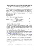
FIGURE 5.17: A plot of the resolution vs. oversampling ratio for different types of delta-sigma
converters and Nyquist sampling converter.
L = 3 adds 3.5 bits of resolution. Therefore, compared to the first-order system, by employing a
higher order delta-sigma converter architecture, the same resolution can be achieved with a lower
samplingfrequency,orahigherinputbandwidthcanbeallowedatthesameresolutionwiththesame
sampling frequency. Figure 5.17 shows a plot of Eq. 5.17 comparing resolution vs. oversampling
ratio for different order delta-sigma converters.
A second-order delta-sigma converter can be realized as shown in Fig. 5.18 w ith two integrators.
Higher order converters can be similarly constructed. However, when the order of the converter
is greater than two, special care must be taken to insure the converter stability [9]. More zeroes
are introduced in the transfer function of the forward path to suppress the signal swing after the
integrators.
c
1999 by CRC Press LLC
FIGURE 5.18: Block diagram of a second order D-S modulator.
Other methods can be used to improve the resolution of the delta-sigma converter. A first-order
and a second-order converter can be cascaded to achieve the same performance as a third-order
converter, but with better stability over the frequency range [10]. A multi-bit quantizer can also
be used to replace the 1-bit quantizer in the architecture presented here [11]. This improves the
resolution at the same sampling speed. Interested readers are referred to reference articles.
In an oversampling converter, the digital decimation filter is also an integral part. Only after the
decimation filter is the resolution of the converter realized. The design of decimation filters are
discussed in other sections of this book and can also be found in the reference article by Candy [12].
References
[1] Grebene, A.B., Bipolar and MOS Analog Integrated Circuit Design, John Wiley & Sons, New
York, 1984.
[2] Sheingold, D.H., Ed.,
Analog-Digital Conversion Handbook, Prentice-Hall, Englewood Cliffs,
NJ, 1986.
[3] Toumazou, C., Lidgey F.J., and Haigh, D.G., eds.,
Analogue IC Design: The Current-Mode
Approach,
Peter Peregrinus Ltd., London, 1990.
[4] Gray, P.R., Hodges, D.A., Broderson, R.W., eds.,
Analog MOS Integrated Circuits, IEEE Press,
New York, 1980.
[5] Gray, P.R., Wooley, B.A., Broderson, R.W., eds.,
Analog MOS Integrated Circuits, II, IEEE
Press, New York, 1989.
[6] Lee, S.H, Song B.S, Digital-domain calibration of multistep analog-to-digital converters,
IEEE
J. Solid-State Circuits,
27: (12) 1679–1688, Dec., 1992.
[7] Inose, H. and Yasuda, Y., A unity bit coding method by negative feedback,
Proc. IEEE, 51:
1524–1535, Nov., 1963.
[8] Gray, R.M., Oversampled sigma-delta modulation,
IEEE Trans. Commun.,35: 481–489, May,
1987.
[9] Chao, K.C-H., Nadeem, S., Lee, W.L., Sodini, C.G., A higher order topology for interpolative
modulatorsforoversampledA/Dconverters,
IEEETrans.CircuitsandSyst.,CAS-37: 309–318,
March, 1990.
[10] Matsuya, Y., Uchimura, K., Iwata, A., Kobayashi, T., Ishikawa, M., and Yoshitoma, T., A 16-bit
oversampling A-to-D conversion technology using triple-integration noise shaping,
IEEE J.
Solid-State Circuits,
SC-22: 921–929, Dec., 1987.
[11] Larson, L.E., Cataltepe, T., and Temes, G.C., Multibit oversampled
− A/D converter with
digital error correction,
Electron. Lett., 24: 1051–1052, Aug., 1988.
[12] Candy, J.C.,Decimationforsigmadeltamodulation,
IEEETrans. Commun.,COM-24: 72–76,
Jan., 1986.
c
1999 by CRC Press LLC