Tài liệu Vẽ kỹ thuật với Autocad 2005 P2 docx
Bạn đang xem bản rút gọn của tài liệu. Xem và tải ngay bản đầy đủ của tài liệu tại đây (483.23 KB, 10 trang )
A hierarchy of title bars
Like most Windows programs, AutoCAD has a title bar at the top of its pro-
gram window that reminds you which program you’re in (not that you’d ever
mistake the AutoCAD window for, say, Microsoft Word!).
ߜ At the right side of the title bar is the standard set of three Windows
control buttons: Minimize, Maximize/Restore, and Close.
ߜ Each drawing window within the AutoCAD program window has its own
title bar. You use the control buttons on a drawing window’s title bar to
minimize, maximize/un-maximize, or close that drawing, not the entire
AutoCAD program.
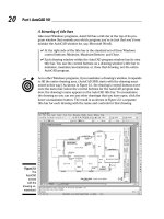
As in other Windows programs, if you maximize a drawing’s window, it expands
to fill the entire drawing area. (AutoCAD 2005 starts with the drawing maxi-
mized in this way.) As shown in Figure 2-1, the drawing’s control buttons move
onto the menu bar, below the control buttons for the AutoCAD program win-
dow; the drawing’s name appears in the AutoCAD title bar. To un-maximize
the drawing so you can see any other drawings that you have open, click the
lower un-maximize button. The result is as shown in Figure 2-2: a separate
title bar for each drawing with the name and controls for that drawing.
Figure 2-2:
The
AutoCAD
screen
with the
drawing un-
maximized.
20
Part I: AutoCAD 101
d571389 Ch02.qxd 4/12/04 9:43 AM Page 20
Making choices from the menu bar
The menu bar contains the names of all the primary menus in your version of
AutoCAD. As with any program that’s new to you, it’s worth spending a few
minutes perusing the menus in order to familiarize yourself with the com-
mands and their arrangement. (If your menu bar doesn’t include the Express
menu, see the end of Chapter 1 for installation instructions.)
Cruising the toolbars
As in other Windows programs, the toolbars in AutoCAD 2005 provide rapid
access to the most commonly used AutoCAD commands. AutoCAD ships with
toolbars in this default arrangement (as shown in Figure 2-3):
ߜ Standard toolbar: Located on top, just below the menu bar; file manage-
ment and other common Windows functions, plus some specialized
AutoCAD stuff such as zooming and panning.
ߜ Styles toolbar: To the right of the Standard toolbar; analogous to the
left part of the Formatting toolbar in Microsoft programs, but formatting
of AutoCAD’s text, dimension, and table styles. (Table styles are new in
AutoCAD 2005.) Chapters 9 and 10 cover these features.
ߜ Layers toolbar: Beneath the Standard toolbar; commands and a drop-
down list for manipulating layers, which are AutoCAD’s fundamental
tools for organizing and formatting objects. Chapter 4 contains the layer
lowdown.
ߜ Properties toolbar: To the right of the Layers toolbar; analogous to the
right part of the Formatting toolbar in Microsoft programs, but formatting
of AutoCAD’s properties, such as colors, linetypes, and lineweights. See
Chapter 4 when you’re ready to play with AutoCAD’s object properties.
ߜ Draw toolbar: Vertically down the far-left edge of the screen; the most
commonly used commands from the Draw menu. Chapter 5 covers most
of the items on this toolbar.
21
Chapter 2: Le Tour de AutoCAD 2005
Hot-wiring the menu bar
Some standard tips and tricks for Windows are
especially useful in AutoCAD. Control-key short-
cuts for the most popular functions — Ctrl+S to
save, Ctrl+O to open a file, and Ctrl+P to print —
work the same way in AutoCAD as in most other
Windows programs. Use them!
Also worth exploring are the Alt-key shortcuts,
which are available for all menu choices, not just
the most popular ones. To fly around the menus,
just press and hold the Alt key and then press
the letters on your keyboard that correspond to
the underlined letters on the menu bar and in the
menu choices. To bring up the SAVEAS com-
mand, for example, just press and hold the Alt key,
press F for File, and then press A for Save As.
d571389 Ch02.qxd 4/12/04 9:43 AM Page 21
ߜ Modify toolbar: Vertically down the far-right edge of the screen; the
most commonly used commands from the Modify menu. Chapter 8
shows you how to use almost everything on this toolbar.
ߜ Draw Order toolbar: Beneath the Modify toolbar; commands for con-
trolling which objects appear on top of which other objects. Chapter 13
mentions these features.
You can rearrange, open, and close toolbars as in other Windows programs:
ߜ To move a toolbar, point to its border (the double-line control handle at
the leading edge of the toolbar is the easiest part to grab), click, and drag.
ߜ To open or close toolbars, right-click on any toolbar button and choose
from the list of available toolbars, as shown in Figure 2-3.
The AutoCAD screen in Figure 2-3 shows the default toolbar arrangement,
which works fine for most people. Feel free to close the Draw Order toolbar;
you aren’t likely to use its features frequently. You may want to turn on a
couple of additional toolbars, such as Object Snap and Dimension, as you dis-
cover and make use of additional features. Throughout this book, I point out
when a particular toolbar may be useful.
Standard toolbar
Draw Order toolbar
Draw toolbar
Layer toolbar
Properties toolbar
Styles toolbar
Modify toolbar
Figure 2-3:
A toolbar
tasting.
22
Part I: AutoCAD 101
d571389 Ch02.qxd 4/12/04 9:43 AM Page 22
If you’re not satisfied with just rearranging the stock AutoCAD toolbars, you
can customize their contents or even create new ones. The procedures are
beyond the scope of this book; they involve bouncing among the Commands,
Toolbars, and Properties tabs on the Customize dialog box in not entirely
intuitive ways. Resist slicing and dicing the stock AutoCAD toolbars until
you’re at least somewhat familiar with them. If you want to get creative there-
after, go to the Contents tab of the AutoCAD 2005 online help and choose
Customization Guide➪Basic Customization➪Create Custom Toolbars.
AutoCAD toolbar buttons provide ToolTips, those short text descriptions that
appear in little yellow boxes when you pause the cursor over a toolbar button.
A longer description of the icon’s function appears in the status bar at the
bottom of the screen.
Looking for Mr. Status Bar
The status bar appears at the bottom of the AutoCAD screen, as shown in
Figure 2-4. The status bar displays and allows you to change several impor-
tant settings that affect how you draw and edit in the current drawing. Some
of these settings won’t make complete sense until you’ve used the AutoCAD
commands that they influence, but here’s a brief description, with pointers to
detailed descriptions of how to use each setting elsewhere in this book:
ߜ Coordinates of the cursor: The cursor coordinates readout displays the
current X,Y,Z location of the cursor in the drawing area, with respect to
the origin point (whose coordinates are 0,0,0). It’s a bit like having a GPS
(Global Positioning System) device in your drawing. Chapter 4 describes
AutoCAD’s coordinate conventions and how to use this area of the
status bar.
23
Chapter 2: Le Tour de AutoCAD 2005
The toolbars that ET AutoCAD
If you’ve installed the Express Tools, you’ll also
see a flock of Express Tools toolbars, whose
labels begin with “ET:”, floating over the draw-
ing area. These four small toolbars collect some
of the most popular Express Tools. You’ll proba-
bly want to close most of these or at least dock
any favorites along the margin of the AutoCAD
window.
The toolbars are extensions to AutoCAD, not
part of the core program, so turning them on is
a little more complicated than just using the
right-click toolbars menu. Right-click on any
toolbar, choose Customize, click the Toolbars
tab on the Customize dialog box, and choose the
EXPRESS Menu Group. Now the Toolbars list
displays the names of the four Express Tools
toolbars; click the check boxes next to the
names in order to toggle each toolbar on or off.
d571389 Ch02.qxd 4/12/04 9:43 AM Page 23
If the coordinates in the lower-left corner of the screen are grayed out,
then coordinate tracking is turned off. Click the coordinates so that they
appear in dark lettering that changes when you move the cursor in the
drawing area.
ߜ SNAP, GRID, and ORTHO mode buttons: These three buttons control
three of AutoCAD’s tools for ensuring precision drawing and editing:
• Snap constrains the cursor to regularly spaced hot spots, enabling
you to draw objects a fixed distance apart more easily.
• Grid displays a series of regularly spaced dots, which serve as a
distance reference.
• Ortho constrains the cursor to horizontal and vertical relative
movement, which makes drawing orthogonal (straight horizontal
and vertical) lines easy.
See Chapter 3 for instructions on how to configure these modes and
Chapter 4 for information about why, when, and how to use them in
actual drawing operations.
ߜ POLAR tracking mode button: Polar tracking causes the cursor to
prefer certain angles when you draw and edit objects. By default, the
preferred angles are multiples of 90 degrees, but you can specify other
angle increments, such as 45 or 30 degrees. See Chapter 4 for instruc-
tions to specify the polar tracking angles that you prefer. Clicking the
POLAR button toggles polar tracking on or off. Ortho and polar tracking
are mutually exclusive — turning on one mode disables the other.
ߜ Running Object Snap (OSNAP) and Object Snap Tracking (OTRACK)
buttons: Object snap is another AutoCAD tool for ensuring precision
drawing and editing. You use object snaps to grab points on existing
objects — for example, the endpoint of a line or the center of a circle.
• When you turn on running object snap, AutoCAD continues to hunt
for object snap points. Chapter 4 contains detailed instructions on
how to use this feature.
• When you turn on object snap tracking, AutoCAD hunts in a more
sophisticated way for points that are derived from object snap
points. Chapter 4 briefly describes this advanced feature.
Cursor coordinates
Snap on/off
Ortho on/off
Running object on/off
Lineweight display on/off
Polar tracking on/off
Object snap tracking on/off
Cursor in model space or paper space
Manage Xrefs
Status bar menu
Communication center
Figure 2-4:
Status (bar)
check.
24
Part I: AutoCAD 101
d571389 Ch02.qxd 4/12/04 9:43 AM Page 24
AutoCAD LT doesn’t include the object snap tracking feature, so you
won’t see an OTRACK button on its status bar.
ߜ Lineweight (LWT) display mode button: One of the properties that you
can assign to objects in AutoCAD is lineweight — the thickness that lines
appear when you plot the drawing. This button controls whether you
see the lineweights on the screen. (This button doesn’t control whether
lineweights appear on plots; that’s a separate setting in the Plot dialog
box.) Chapter 4 gives you the skinny (and the wide) on lineweights.
ߜ MODEL/PAPER space button: As I describe in the section “Main course:
The drawing area” later in this chapter, the drawing area is composed of
overlapping tabbed areas labeled Model, Layout1, and Layout2 by default.
The Model tab displays a part of the drawing called model space, where
you create most of your drawing. Each of the remaining tabs displays a
paper space layout, where you can compose a plotable view with a title
block. A completed layout will include one or more viewports, which
reveal some or all the objects in model space at a particular scale.
The MODEL/PAPER status bar button (not to be confused with the Model
tab) comes into play after you click one of the paper space layout tabs.
The MODEL/PAPER button provides a means for moving the cursor
between model and paper space while remaining in the particular layout.
• When the MODEL/PAPER button says MODEL, drawing and editing
operations take place in model space, inside a viewport.
• When the button says PAPER, drawing and editing operations take
place in paper space on the current layout.
Don’t worry if you find model space and paper space a little disorienting
at first. The paper space layout setup information in Chapter 3 and plot-
ting instructions in Chapter 12 will help you get your bearings and navi-
gate with confidence.
ߜ Maximize/Minimize Viewport button (paper space layouts only): When
you’re looking at one of the Layout tabs instead of the Model tab, the
status bar displays an additional Maximize Viewport button. Click this
button to expand the current paper space viewport so that it fills the
entire drawing area. Click the button — now called Minimize Viewport —
again to restore the viewport to its normal size. (Chapter 3 describes
viewports.)
ߜ Communication Center: This button opens a dialog box containing
recent AutoCAD-related headlines that Autodesk thinks you may find
useful. The headlines are grouped into categories called channels: Live
Update Maintenance Patches, Articles and Tips, Product Support
Information, and so on. Each headline is a link to a Web page with more
information, such as how to download a software update or fix a prob-
lem. Click the Settings button to select channels you see in the
Communication Center window.
ߜ Manage Xrefs: You won’t see this combination button and notification
symbol until you open a drawing that contains xrefs (external DWG files
25
Chapter 2: Le Tour de AutoCAD 2005
d571389 Ch02.qxd 4/12/04 9:43 AM Page 25
that are incorporated into the current drawing). Chapter 13 tells you
how to use xrefs and what the Manage Xrefs button does.
ߜ Status Bar Menu: When you click the easy-to-miss downward-pointing
arrow near the right edge of the status bar, you open a menu with
options for toggling off or on each status bar button. Now you can deco-
rate your status bar to your taste.
You can open dialog boxes for configuring many of the status bar button
functions by right-clicking the status bar button and choosing Settings.
Chapters 3 and 4 give you specific guidance about when and how to change
these settings.
A button’s appearance shows whether the setting is turned on or off.
Depressed, or down, means on; raised, or up, means off. If you’re unclear
whether a setting is on or off, click its button; its mode will change and the
new setting will be reflected on the command line —
<Osnap off>, for exam-
ple. Click again to restore the previous setting.
Take an order: The command line area
If the title bars, menu bar, and status bar are the Windows equivalent of com-
fort food — familiar, nourishing, and unthreatening — then the command
line area, shown in Figure 2-5, must be the steak tartare or blood sausage of
the AutoCAD screen feast. It looks weird, turns the stomachs of newcomers,
and delights AutoCAD aficionados. The hard truth is that you have to come
to like — or at least tolerate — the command line if you want to become at
all comfortable using AutoCAD.
You need to get up close and personal with the command line for four reasons:
ߜ The command line area is AutoCAD’s primary communications con-
duit with you. This is the most important reason to pay attention to the
command line. AutoCAD frequently displays prompts, warnings, and
error messages in the command line area. If you don’t keep an eye on
this area, you’ll miss a lot of vital information. You’ll continually be frus-
trated, because you won’t “hear” what AutoCAD is trying to tell you.
ߜ The command line is an efficient way to run some commands and the
only way to run a few others. Instead of clicking a toolbar button or a
Figure 2-5:
Obey the
command
line.
26
Part I: AutoCAD 101
d571389 Ch02.qxd 4/12/04 9:43 AM Page 26
menu choice, you can start a command by typing its command name and
then pressing the Enter key. Even better, you can type the keyboard short-
cut for a command name and press Enter. Most of the keyboard shortcuts
for command names are just one or two letters — for example, L for the
LINE command and CP for the COPY command. Most people who dis-
cover how to use the shortcuts for the commands that they run most fre-
quently find that their AutoCAD productivity improves noticeably. Even if
you’re not worried about increasing your productivity with this technique,
there are some commands that aren’t on the toolbars or pull-down menus.
If you want to run those commands, you have to type them!
ߜ After you’ve started a command — whether from a toolbar, from a
menu, or by typing — the command line is where AutoCAD prompts
you with options for that command.
You activate one of these options by typing the uppercase letter(s) in
the option and pressing Enter.
In many cases, you can activate a command’s options by right-clicking in
the drawing area and choosing the desired option from the right-click
menu, instead of by typing the letter(s) for the option and pressing
Enter. But if you don’t watch the command line, you probably won’t real-
ize that there are any options!
ߜ You sometimes need to type coordinates at the command line to specify
precise points or distances. Chapter 4 describes this technique in detail.
You don’t have to click in the command line area to type command names,
keyboard shortcuts, or command options there. AutoCAD knows that your
typing is supposed to go to the command line. The only exception is when
you’re within a text command (you’re adding a text note to the drawing itself);
in that case, the text appears in the drawing, not in the command line area.
The following sequence demonstrates how you use the command line area to
run commands, view and select options, and pay attention to messages from
AutoCAD:
1. Type L and press Enter.
AutoCAD starts the LINE command and displays the following prompt in
the command line area:
LINE Specify first point:
2. Click a point anywhere in the drawing area.
The command line prompt changes to:
Specify next point or [Undo]:
AutoCAD always displays command options in brackets. In this case, the
Undo option appears in brackets. To activate the option, type the letter(s)
shown in uppercase and press Enter. (You can type the option letter(s) in
lowercase or uppercase.)
27
Chapter 2: Le Tour de AutoCAD 2005
d571389 Ch02.qxd 4/12/04 9:43 AM Page 27
3. Click another point anywhere in the drawing area.
AutoCAD draws the first line segment.
4. Click a third point anywhere in the drawing area.
AutoCAD draws the second line segment. The command line prompt
changes to:
Specify next point or [Close/Undo]:
AutoCAD now displays two options, Close and Undo, separated by a
slash.
5. Type U and press Enter.
AutoCAD undoes the second line segment.
6. Type 3,2 (without any spaces) and press Enter.
AutoCAD draws a new line segment to the point whose the X coordinate
is 3 and the Y coordinate is 2.
7. Click several more points anywhere in the drawing area.
AutoCAD draws additional line segments.
8. Type X and press Enter.
AutoCAD displays an error message (because X isn’t a valid option of
the LINE command) and reprompts for another point:
Point or option keyword required.
Specify next point or [Close/Undo]:
Option keyword is programmer jargon for the letter(s) shown in upper-
case that you type to activate a command option. This error message is
AutoCAD’s way of saying “I don’t understand what you mean by typing
‘X.’ Either specify a point or type a letter that I do understand.”
9. Type C and press Enter.
AutoCAD draws a final line segment, which creates a closed figure, and
ends the LINE command. The naked command prompt returns, indicat-
ing that AutoCAD is ready for the next command:
Command:
10. Press the F2 key.
AutoCAD displays the AutoCAD Text Window, which is simply an
enlarged, scrollable version of the command line area, as shown in
Figure 2-6.
The normal three-line command line area usually shows you what you
need to see, but occasionally you’ll want to review a larger chunk of com-
mand line history (“what was AutoCAD trying to tell me a minute ago?!”).
11. Press the F2 key again.
AutoCAD closes the AutoCAD Text Window.
28
Part I: AutoCAD 101
d571389 Ch02.qxd 4/12/04 9:43 AM Page 28
Here are a few other tips and tricks for using the command line effectively:
ߜ Use the Esc key to bail out of the current operation. There will be
times when you get confused about what you’re doing in AutoCAD
and/or what you’re seeing in the command line area. If you need to bail
out of the current operation, just press the Esc key one or more times
until you see the naked command prompt —
Command: at the bottom of
the command line area, with nothing after it. As in most other Windows
programs, Esc is the cancel key. Unlike many other Windows programs,
AutoCAD keeps you well informed of whether an operation is in
progress. The naked command prompt indicates that AutoCAD is in a
quiescent state, waiting for your next command.
ߜ Press Enter to accept the default action. Some command prompts
include a default action in angled brackets. For example, the first prompt
of the POLygon command is
Enter number of sides <4>:
The default here is four sides, and you can accept it simply by pressing
the Enter key. (That is, you don’t have to type 4 first.)
AutoCAD uses two kinds of brackets in command line prompts.
• Command options appear in regular brackets: [Close/Undo].
To activate a command option, type the letter(s) that appear in
uppercase and then press Enter.
Figure 2-6:
My how
you’ve
grown: F2
expands the
command
line area to
a command
text
window.
29
Chapter 2: Le Tour de AutoCAD 2005
d571389 Ch02.qxd 4/12/04 9:43 AM Page 29