Tài liệu LUBRICATION OF MACHINE ELEMENTS P1 pdf
Bạn đang xem bản rút gọn của tài liệu. Xem và tải ngay bản đầy đủ của tài liệu tại đây (1006.9 KB, 17 trang )
By
the
middle
of
this century
two
distinct regimes
of
lubrication were generally recognized.
The first
of
these
was
hydrodynamic lubrication.
The
development
of the
understanding
of
this lubrication
regime began with
the
classical experiments
of
Tower,
1
in
which
the
existence
of a film was
detected
from
measurements
of
pressure within
the
lubricant,
and of
Petrov,
2
who
reached
the
same conclusion
from
friction
measurements. This work
was
closely followed
by
Reynolds' celebrated analytical
paper
3
in
which
he
used
a
reduced
form
of the
Navier-Stokes
equations
in
association with
the
continuity equation
to
generate
a
second-order
differential
equation
for the
pressure
in the
narrow,
converging
gap of a
bearing contact. Such
a
pressure enables
a
load
to be
transmitted between
the
surfaces
with very
low
friction
since
the
surfaces
are
completely separated
by a film of fluid. In
such
a
situation
it is the
physical properties
of the
lubricant, notably
the
dynamic viscosity, that dictate
the
behavior
of the
contact.
The
second lubrication regime clearly recognized
by
1950
was
boundary lubrication.
The
under-
standing
of
this lubrication regime
is
normally attributed
to
Hardy
and
Doubleday,
4
-
5
who
found
that
very
thin
films
adhering
to
surfaces were
often
sufficient
to
assist relative sliding. They concluded
that
under such circumstances
the
chemical composition
of the fluid is
important,
and
they introduced
the
term "boundary
lubrication."
Boundary lubrication
is at the
opposite
end of the
lubrication
Mechanical
Engineers' Handbook,
2nd
ed., Edited
by
Myer
Kutz.
ISBN
0-471-13007-9
©
1998 John Wiley
&
Sons, Inc.
CHAPTER
21
LUBRICATION
OF
MACHINE
ELEMENTS
Bernard
J.
Hamrock
Department
of
Mechanical
Engineering
Ohio
State University
Columbus,
Ohio
SYMBOLS
508
21.1 LUBRICATION
FUNDAMENTALS
512
21.1.1
Conformal
and
Nonconformal
Surfaces
512
21.1.2
Bearing Selection
513
21.1.3
Lubricants
516
21.1.4
Lubrication Regimes
518
21.1.5
Relevant Equations
520
21.2 HYDRODYNAMIC
AND
HYDROSTATIC
LUBRICATION
523
21.2.1
Liquid-Lubricated
Hydrodynamic
Journal
Bearings
524
21.2.2
Liquid-Lubricated
Hydrodynamic
Thrust
Bearings
530
21.2.3
Hydrostatic Bearings
536
21.2.4 Gas-Lubricated
Hydrodynamic Bearings
545
21.3 ELASTOHYDRODYNAMIC
LUBRICATION
556
21.3.1
Contact
Stresses
and
Deformations
558
21.3.2 Dimensionless Grouping
566
21.3.3
Hard-EHL
Results
568
21.3.4
Soft-EHL Results
572
21.3.5
Film Thickness
for
Different
Regimes
of
Fluid-Film
Lubrication
573
21.3.6
Rolling-Element Bearings
576
21.4
BOUNDARYLUBRICATION
616
21.4.1
Formation
of
Films
618
21.4.2
Physical Properties
of
Boundary
Films
619
21.4.3
Film Thickness
621
21.4.4
Effect
of
Operating
Variables
621
21.4.5
Extreme-Pressure (EP)
Lubricants
623
spectrum
from
hydrodynamic
lubrication.
In
boundary lubrication
it is the
physical
and
chemical
properties
of
thin
films of
molecular proportions
and the
surfaces
to
which they
are
attached that
determine contact behavior.
The
lubricant viscosity
is not an
influential
parameter.
In
the
last
30
years research
has
been devoted
to a
better understanding
and
more precise
definition
of
other lubrication regimes between these extremes.
One
such lubrication regime occurs
in
noncon-
formal
contacts, where
the
pressures
are
high
and the
bearing surfaces deform elastically.
In
this
situation
the
viscosity
of the
lubricant
may
rise considerably,
and
this
further
assists
the
formation
of
an
effective
fluid film. A
lubricated contact
in
which such
effects
are to be
found
is
said
to be
operating
elastohydrodynamically.
Significant
progress
has
been made
in our
understanding
of the
mechanism
of
elastohydrodynamic
lubrication, generally viewed
as
reaching maturity.
This chapter describes
briefly
the
science
of
these three lubrication regimes (hydrodynamic, elas-
tohydrodynamic,
and
boundary)
and
then demonstrates
how
this science
is
used
in the
design
of
machine elements.
SYMBOLS
A
p
total projected
pad
area,
m
2
a
b
groove width ratio
a
f
bearing-pad load
coefficient
B
total conformity
of
ball bearing
b
semiminor
axis
of
contact,
m;
width
of
pad,
m
b
length ratio,
b
s
lb
r
b
g
length
of
feed
groove region,
m
b
r
length
of
ridge region,
m
b
s
length
of
step region,
m
C
dynamic load capacity,
N
C
1
load
coefficient,
FIp
0
Rl
c
radial clearance
of
journal bearing,
m
c'
pivot circle clearance,
m
c
b
bearing clearance
at pad
minimum
film
thickness (Fig.
21.16),
m
c
d
orifice
discharge
coefficient
D
distance between race curvature centers,
m
D
material
factor
D
x
diameter
of
contact ellipse along
x
axis,
m
D
y
diameter
of
contact ellipse along
y
axis,
m
d
diameter
of
rolling element
or
diameter
of
journal,
m
d
a
overall diameter
of
ball bearing (Fig. 21.76),
m
d
b
bore diameter
of
ball bearing,
m
d
c
diameter
of
capillary tube,
m
df
inner-race diameter
of
ball bearing,
m
d
0
outer-race diameter
of
ball bearing,
m
d
0
diameter
of
orifice,
m
E
modulus
of
elasticity,
NYm
2
/1
-
v
2
a
1 -
vlY
1
E'
effective
elastic modulus,
2
I
1
I ,
NYm
2
\
E
0
E
b
/
E
metallurgical processing
factor
&
elliptic integral
of
second kind
e
eccentricity
of
journal bearing,
m
F
applied normal load,
N
F'
load
per
unit length,
N/m
F
lubrication
factor
5
elliptic integral
of first
kind
F
c
pad
load component along line
of
centers (Fig. 21.41),
N
F
e
rolling-element-bearing equivalent load,
N
F
r
applied radial load,
N
F
5
pad
load component normal
to
line
of
centers (Fig. 21.41),
N
F
t
applied thrust load,
N
/
race conformity ratio
f
c
coefficient
dependent
on
materials
and
rolling-element bearing type (Table
21.19)
G
dimensionless materials parameter
G
speed
effect
factor
G
f
groove factor
g
e
dimensionless elasticity parameter,
W
8
^IU
2
g
v
dimensionless viscosity parameter,
GW
3
JU
2
H
dimensionless
film
thickness,
hiR
x
H
misalignment factor
H
a
dimensionless
film
thickness ratio,
h
s
lh
r
H
b
pad
pumping power,
N
m/sec
H
0
power consumed
in
friction
per
pad,
W
H
f
pad
power
coefficient
H
min
dimensionless minimum
film
thickness,
h
min
/R
x
fi
min
dimensionless minimum
film
thickness,
H
min
(W/U)
2
Hp
dimensionless pivot
film
thickness,
h
p
/c
H
t
dimensionless
trailing-edge
film
thickness,
h
t
lc
h film
thickness,
m
h
t
film
thickness ratio,
H
1
Ih
0
h
{
inlet
film
thickness,
m
h
t
leading-edge
film
thickness,
m
/z
min
minimum
film
thickness,
m
h
0
outlet
film
thickness,
m
h
p
film
thickness
at
pivot,
m
h
r
film
thickness
in
ridge region,
m
h
s
film
thickness
in
step region,
m
h
t
film
thickness
at
trailing edge,
m
/Z
0
film
constant,
m
J
number
of
stress cycles
K
load deflection constant
K
dimensionless
stiffness
coefficient,
cK
p
lpJ^l
K
a
dimensionless
stiffness,
—c
dW/dc
K
p
film
stiffness,
N/m
K
1
load-deflection constant
for a
roller bearing
K
15
load-deflection constant
for a
ball bearing
K
00
dimensionless
stiffness,
cKplpJtl
k
ellipticity parameter,
D
y
ID
x
k
c
capillary tube constant,
m
3
k
0
orifice constant,
m
4
/N
1/2
sec
L
fatigue
life
L
0
adjusted fatigue
life
L
10
fatigue
life
where
90% of
bearing population will endure
L
50
fatigue
life
where
50% of
bearing population will endure
/
bearing length,
m
1
0
length
of
capillary tube,
m
l
r
roller
effective
length,
m
l
t
roller
length,
m
l
v
length dimension
in
stress volume,
m
1
1
total axial length
of
groove,
m
M
probability
of
failure
M
stability parameter,
mp
a
h
5
r
/2R
5
/rf
m
number
of
rows
of
rolling elements
m
mass supported
by
bearing,
N
sec
2
/m
m
p
preload
factor
N
rotational speed,
rps
N
R
Reynolds number
n
number
of
rolling elements
or
number
of
pads
or
grooves
P
dimensionless pressure,
piE'
P
d
diametral clearance,
m
P
e
free
endplay,
m
p
pressure,
N/m
2
p
a
ambient pressure,
N/m
2
P
1
lift
pressure,
N/m
2
/?
max
maximum pressure,
N/m
2
p
r
recess pressure,
N/m
2
p
s
bearing supply pressure,
N/m
2
Q
volume
flow of
lubricant,
m
3
/sec
Q
dimensionless
flow,
3r]Q/7rp
a
h
3
r
Q
0
volume
flow of
lubricant
in
capillary,
m
3
/sec
Q
0
volume
flow of
lubricant
in
orifice,
m
3
/sec
Q
s
volume side
flow of
lubricant,
m
3
/sec
q
constant,
TT/2
- 1
q
f
bearing-pad
flow
coefficient
R
curvature
sum on
shaft
or
bearing radius,
m
R
groove length
fraction,
(R
0
-
R
8
)/(R
0
-
R
1
)
R
g
groove radius (Fig. 21.60),
m
R
0
orifice
radius,
m
R
x
effective
radius
in x
direction,
m
Ry
effective
radius
in
3;
direction,
m
R
1
outer radius
of
sector thrust bearing,
m
R
2
inner radius
of
sector thrust bearing,
m
r
race curvature radius,
m
r
c
roller corner radius,
m
S
probability
of
survival
Sm
Sommerfeld
number
for
journal bearings,
r]Nd
3
l/2Fc
2
Sm
t
Sommerfeld number
for
thrust bearings,
j]ubl
2
IFhl
s
shoulder height,
m
T
tangential force,
N
f
dimensionless torque,
6
T
r
lirpJ(R\
+
R%)
h
r
h
c
T
0
critical temperature
T
r
torque,
N m
U
dimensionless speed parameter,
urj
Q
/E'R
x
u
mean
surface
velocity
in
direction
of
motion,
m/sec
v
elementary volume,
m
3
N
dimensionless load parameter,
FIE'R
2
W
dimensionless load capacity,
F/pJ(b
r
+
b
s
+
b
g
)
W
00
dimensionless load,
l.5G
f
F/irp
a
(R^
-
R
2
,)
X,
Y
factors
for
calculation
of
equivalent load
;c,v,z
coordinate system
x
distance
from
inlet edge
of pad to
pivot,
m
a.
radius ratio,
RyIR
x
a
a
offset
factor
a
b
groove width ratio,
b
s
l(b
r
+
b
s
)
a
p
angular extent
of
pad,
deg
a
r
radius ratio,
R
2
IR
1
(3
contact angle,
deg
/3'
iterated value
of
contact angle,
deg
p
a
groove angle,
deg
fi
f
free
or
initial contact angle,
deg
P
p
angle between load direction
and
pivot,
deg
F
curvature
difference
y
groove length ratio,
I
1
Il
A
rms
surface
finish,
m
8
total elastic deformation,
m
e
eccentricity
ratio,
elc
TJ
absolute viscosity
of
lubricant,
N
sec/m
2
r\
k
kinematic viscosity,
Wp,
m
2
/sec
Tfo
viscosity
at
atmospheric pressure,
N
sec/m
2
6
angle used
to
define
shoulder height,
deg
0
dimensionless step location,
OJ(B
1
+
O
0
)
O
g
angular extent
of
lubrication
feed
groove,
deg
0
1
angular extent
of ridge
region,
deg
0
0
angular extent
of
step region,
deg
A
film
parameter (ratio
of
minimum
film
thickness
to
composite surface roughness)
A
c
dimensionless
bearing
number,
3>j]a)(R*
-
R
2
^Ip
0
H
2
A
7
dimensionless bearing number,
6rja)R
2
/p
a
c
2
A,
dimensionless bearing number,
6rjul/p
a
h
2
A
length-to-width ratio
A
a
length ratio,
(b
r
+
b
s
+
b
g
)ll
X
b
(1 +
2/Sa)-
1
IJL
coefficient
of
friction,
TIF
v
Poisson's
ratio
£
pressure-viscosity
coefficient
of
lubricant,
m
2
/N
g
p
angle between line
of
centers
and pad
leading edge,
deg
p
lubricant density,
N
sec
2
/m
4
PQ
density
at
atmospheric pressure,
N
sec
2
/m
4
cr
max
maximum Hertzian
stress,
N/m
2
T
shear stress,
N/m
2
T
0
maximum shear stress,
N/m
2
4>
attitude angle
in
journal bearings,
deg
4>
p
angle between
pad
leading edge
and
pivot,
deg
^
angular location,
deg
ifj
t
angular limit
of
if/,
deg
*l/
s
step location parameter,
b
s
l(b
r
+
b
s
+
b
g
)
a)
angular velocity,
rad/sec
a}
B
angular velocity
of
rolling-element race contact, rad/sec
a)
b
angular velocity
of
rolling element about
its own
center,
rad/sec
a)
c
angular velocity
of
rolling element about
shaft
center,
rad/sec
a>
d
rotor whirl
frequency,
rad/sec
lo
d
whirl
frequency
ratio,
(o
d
/a)j
o)j
journal rotational speed, rad/sec
Sub-
scripts
a
solid
a
b
solid
b
EHL
elastohydrodynamic
lubrication
e
elastic
HL
hydrodynamic
lubrication
1
inner
Fig.
21.1
Conformal surfaces. (From Ref.
6.)
iv
isoviscous
o
outer
pv
piezoviscous
r rigid
x,y,z
coordinate system
21.1 LUBRICATION FUNDAMENTALS
A
lubricant
is any
substance that
is
used
to
reduce
friction
and
wear
and to
provide smooth running
and
a
satisfactory
life
for
machine elements. Most
lubricants
are
liquids
(like
minerals
oils,
the
synthetic
esters
and
silicone
fluids, and
water),
but
they
may be
solids (such
as
polytetrafluorethylene)
for
use in dry
bearings,
or
gases (such
as
air)
for use in gas
bearings.
An
understanding
of the
physical
and
chemical interactions between
the
lubricant
and the
tribological
surfaces
is
necessary
if
the
machine elements
are to be
provided with satisfactory life.
To
help
in the
understanding
of
this
tribological behavior,
the first
section describes some lubrication fundamentals.
21.1.1
Conformal
and
Nonconformal Surfaces
Hydrodynamic
lubrication
is
generally characterized
by
surfaces that
are
conformal;
that
is, the
sur-
faces
fit
snugly into each other with
a
high degree
of
geometrical conformity
(as
shown
in
Fig.
21.1),
so
that
the
load
is
carried over
a
relatively large area. Furthermore,
the
load-carrying surface remains
essentially constant while
the
load
is
increased. Fluid-film journal bearings
(as
shown
in
Fig.
21.1)
and
slider bearings exhibit conformal surfaces.
In
journal bearings
the
radial clearance between
the
shaft
and
bearing
is
typically one-thousandth
of the
shaft
diameter;
in
slider
bearings
the
inclination
of
the
bearing surface
to the
runner
is
typically
one
part
in a
thousand.
These
converging surfaces,
coupled with
the
fact
that there
is
relative motion
and a
viscous
fluid
separating
the
surfaces, enable
a
positive pressure
to be
developed
and
exhibit
a
capacity
to
support
a
normal applied load.
The
magnitude
of the
pressure developed
/5 not
generally large enough
to
cause significant
elastic
defor-
mation
of the
surfaces.
The
minimum
film
thickness
in a
hydrodynamically
lubricated bearing
is a
function
of
applied load, speed, lubricant viscosity,
and
geometry.
The
relationship between
the
minimum
film
thickness
h
min
and the
speed
u and
applied normal load
F is
given
as
M
1/2
(^mIn)HL
«
M
(2Ll)
More coverage
of
hydrodynamic
lubrication
can be
found
in
Section 21.2.
Many
machine elements have contacting surfaces that
do not
conform
to
each other very well,
as
shown
in
Fig. 21.2
for a
rolling-element bearing.
The
full
burden
of the
load must then
be
carried
by
a
very small contact area.
In
general,
the
contact areas between
nonconformal
surfaces enlarge
considerably
with increasing load,
but
they
are
still smaller than
the
contact areas between conformal
Fig.
21.2
Nonconformal surfaces. (From
Ref.
6.)
surfaces. Some examples
of
nonconformal
surfaces
are
mating gear teeth, cams
and
followers,
and
rolling-element bearings
(as
shown
in
Fig.
21.2).
The
mode
of
lubrication normally
found
in
these
nonconformal
contacts
is
elastohydrodynamic
lubrication.
The
requirements necessary
for
hydrody-
namic
lubrication (converging surfaces, relative motion,
and
viscous
fluid) are
also required
for
elas-
tohydrodynamic lubrication.
The
relationship between
the
minimum
film
thickness
and
normal applied load
and
speed
for an
elastohydrodynamically
lubricated contact
is
№min)EHL
«
F^™
(21.2)
(/W)EHL
«
«°'
68
(21.3)
Comparing
the
results
of
Eqs.
(21.2)
and
(21.3)
with that obtained
for
hydrodynamic
lubrication
expressed
in Eq.
(21.1)
indicates that:
1. The
exponent
on the
normal applied load
is
nearly seven times larger
for
hydrodynamic
lubrication
than
for
elastohydrodynamic lubrication. This implies that
in
elastohydrodynamic
lubrication
the film
thickness
is
only slightly
affected
by
load while
in
hydrodynamic lubri-
cation
it is
significantly
affected
by
load.
2. The
exponent
on
mean velocity
is
slightly higher
for
elastohydrodynamic lubrication
than
that
found
for
hydrodynamic lubrication.
More discussion
of
elastohydrodynamic lubrication
can be
found
in
Section 21.3.
The
load
per
unit area
in
conformal
bearings
is
relatively low, typically averaging only
1
MN/m
2
and
seldom over
7
MN/m
2
.
By
contrast,
the
load
per
unit area
in
nonconformal contacts
will generally exceed
700
MN/m
2
even
at
modest applied loads.
These
high pressures result
in
elastic
deformation
of the
bearing materials such that elliptical contact areas
are
formed
for
oil-film
gener-
ation
and
load support.
The
significance
of the
high contact pressures
is
that they result
in a
consid-
erable increase
in fluid
viscosity. Inasmuch
as
viscosity
is a
measure
of a fluid's
resistance
to flow,
this
increase greatly enhances
the
lubricant's ability
to
support load without being squeezed
out of
the
contact zone.
The
high contact pressures
in
nonconforming
surfaces therefore result
in
both
an
elastic deformation
of the
surfaces
and
large increases
in the fluid's
viscosity.
The
minimum
film
thickness
is a
function
of the
parameters
found
for
hydrodynamic lubrication with
the
addition
of an
effective
modulus
of
elasticity parameter
for the
bearing materials
and a
pressure-viscosity
coefficient
for
the
lubricant.
21.1.2
Bearing Selection
Ball bearings
are
used
in
many kinds
of
machines
and
devices
with rotating parts.
The
designer
is
often
confronted with decisions
on
whether
a
nonconformal bearing such
as a
rolling-element bearing
or
a
conformal bearing such
as a
hydrodynamic bearing should
be
used
in a
particular application.
The
following characteristics make rolling-element bearings more
desirable
than hydrodynamic bear-
ings
in
many situations:
1. Low
starting
and
good operating friction
2. The
ability
to
support combined radial
and
thrust loads
3.
Less
sensitivity
to
interruptions
in
lubrication
4. No
self-excited instabilities
5.
Good low-temperature starting
Within
reasonable limits changes
in
load,
speed,
and
operating temperature have
but
little
effect
on
the
satisfactory performance
of
rolling-element bearings.
The
following characteristics make nonconformal bearings such
as
rolling-element bearings
less
desirable
than
conformal (hydrodynamic) bearings:
1.
Finite fatigue life subject
to
wide
fluctuations
2.
Large space required
in the
radial direction
3. Low
damping capacity
4.
High noise level
5.
More severe alignment requirements
6.
Higher cost
Each type
of
bearing
has its
particular strong points,
and
care should
be
taken
in
choosing
the
most
appropriate type
of
bearing
for a
given application.
The
Engineering Services Data Unit
documents
7
'
8
provide
an
excellent guide
to the
selection
of
the
type
of
journal
or
thrust bearing most likely
to
give
the
required performance when considering
the
load, speed,
and
geometry
of the
bearing.
The
following types
of
bearings were considered:
1.
Rubbing bearings, where
the two
bearing surfaces
rub
together (e.g.,
unlubricated
bushings
made
from
materials based
on
nylon,
polytetrafluoroethylene,
also known
as
PTFE,
and
carbon).
2.
Oil-impregnated porous metal bearings, where
a
porous metal bushing
is
impregnated with
lubricant
and
thus
gives
a
self-lubricating
effect
(as in
sintered-iron
and
sintered-bronze
bearings).
3.
Rolling-element bearings, where relative motion
is
facilitated
by
interposing rolling elements
between stationary
and
moving components
(as in
ball, roller,
and
needle bearings).
4.
Hydrodynamic
film
bearings, where
the
surfaces
in
relative motion
are
kept apart
by
pressures
generated
hydrodynamically
in the
lubricant
film.
Figure
21.3,
reproduced
from
the
Engineering
Sciences
Data Unit
publication,
7
gives
a
guide
to
the
typical load that
can be
carried
at
various speeds,
for a
nominal
life
of
10,000
hr at
room
temperature,
by
journal bearings
of
various types
on
shafts
of the
diameters quoted.
The
heavy curves
Fig.
21.3
General guide
to
journal bearing type. (Except
for
roller bearings, curves
are
drawn
for
bearings with width equal
to
diameter.
A
medium-viscosity mineral
oil
lubricant
is
assumed
for
hydrodynamic
bearings.)
(From
Ref.
7.)
Rubbing bearings
Oil-impregnated porous
metal
bearings
Rolling
bearings
Hydrodynamic
oil-film
bearings
indicate
the
preferred type
of
journal bearing
for a
particular load, speed,
and
diameter
and
thus
divide
the
graph into distinct regions. From Fig. 21.3
it is
observed that rolling-element bearings
are
preferred
at
lower speeds
and
hydrodynamic
oil film
bearings
are
preferred
at
higher speeds. Rubbing
bearings
and
oil-impregnated porous metal bearings
are not
preferred
for any of the
speeds, loads,
or
shaft
diameters considered. Also,
as the
shaft
diameter
is
increased,
the
transitional point
at
which
hydrodynamic bearings
are
preferred over rolling-element bearings moves
to the
left.
The
applied load
and
speed
are
usually known,
and
this enables
a
preliminary assessment
to be
made
of the
type
of
journal bearing most likely
to be
suitable
for a
particular application.
In
many
cases
the
shaft
diameter will have been determined
by
other considerations,
and
Fig. 21.3
can be
used
to find the
type
of
journal bearing that will give adequate load capacity
at the
required speed.
These
curves
are
based
upon good engineering practice
and
commercially available parts. Higher
loads
and
speeds
or
smaller
shaft
diameters
are
possible with exceptionally high engineering standards
or
specially produced materials. Except
for
rolling-element bearings
the
curves
are
drawn
for
bearings
with
a
width equal
to the
diameter.
A
medium-viscosity mineral
oil
lubricant
is
assumed
for the
hydrodynamic bearings.
Similarly, Fig. 21.4, reproduced
from
the
Engineering Sciences Data Unit
publication,
8
gives
a
guide
to the
typical maximum load that
can be
carried
at
various speeds
for a
nominal
life
of
10,000
hr
at
room temperature
by
thrust bearings
of the
various diameters quoted.
The
heavy curves again
indicate
the
preferred type
of
bearing
for a
particular load, speed,
and
diameter
and
thus divide
the
graph
into
major
regions.
As
with
the
journal bearing results (Fig.
21.3)
at the
hydrodynamic bearing
is
preferred
at
lower speeds.
A
difference between Figs. 21.3
and
21.4
is
that
at
very
low
speeds
Fig.
21.4
General guide
to
thrust bearing type. (Except
for
roller bearings, curves
are
drawn
for
typical
ratios
of
inside
to
outside diameter.
A
medium-viscosity mineral
oil
lubricant
is as-
sumed
for
hydrodynamic bearings.)
(From
Ref.
8.)
Rubbing bearings
Oi
I-impregnated
porous
metal
bearings
Rolling
bearings
Hydrodynamic
oil-film
bearings
there
is a
portion
of the
latter
figure
in
which
the
rubbing bearing
is
preferred. Also,
as the
shaft
diameter
is
increased,
the
transitional point
at
which
hydrodynamic
bearings
are
preferred over
rolling-element bearings moves
to the
left.
Note also
from
this
figure
that oil-impregnated porous
metal bearings
are not
preferred
for any of the
speeds, loads,
or
shaft
diameters
considered.
21.1.3
Lubricants
Both
oils
and
greases
are
extensively used
as
lubricants
for all
types
of
machine elements over wide
range
of
speeds, pressures,
and
operating temperatures. Frequently,
the
choice
is
determined
by
considerations other than lubrication requirements.
The
requirements
of the
lubricant
for
successful
operation
of
nonconformal
contacts such
as in
rolling-element bearings
and
gears
are
considerably
more stringent than those
for
conformal
bearings
and
therefore will
be the
primary concern
in
this
section.
Because
of its fluidity oil has
several advantages over
grease:
It can
enter
the
loaded conjunction
most
readily
to flush
away contaminants, such
as
water
and
dirt, and, particularly,
to
transfer heat
from
heavily loaded machine elements. Grease, however,
is
extensively used because
it
permits
simplified
designs
of
housings
and
enclosures, which require less maintenance,
and
because
it is
more
effective
in
sealing against dirt
and
contaminants.
Viscosity
In
hydrodynamic
and
elastohydrodynamic
lubrication
the
most important physical property
of a
lubricant
is its
viscosity.
The
viscosity
of a fluid may be
associated with
its
resistance
to flow,
that
is,
with
the
resistance arising
from
intermolecular
forces
and
internal
friction
as the
molecules move
past
each other. Thick
fluids,
like molasses, have relatively high viscosity; they
do not flow
easily.
Thinner
fluids,
like water, have lower viscosity; they
flow
very easily.
The
relationship
for
internal friction
in a
viscous
fluid (as
proposed
by
Newton)
9
can be
written
as
,=
„£
(21.4)
where
T =
internal shear stress
in the fluid in the
direction
of
motion
77
=
coefficient
of
absolute
or
dynamic viscosity
or
coefficient
of
internal friction
duldz
=
velocity gradient perpendicular
to the
direction
of
motion
(i.e.,
shear rate)
It
follows
from
Eq.
(21.4) that
the
unit
of
dynamic viscosity must
be the
unit
of
shear stress divided
by
the
unit
of
shear rate.
In the
newton-meter-second system
the
unit
of
shear stress
is the
newton
per
square meter while that
of
shear rate
is the
inverse second. Hence
the
unit
of
dynamic viscosity
will
be
newton
per
square meter multiplied
by
second,
or N
sec/m
2
.
In the SI
system
the
unit
of
pressure
or
stress
(N/m
2
)
is
known
as
pascal, abbreviated
Pa, and it is
becoming increasingly common
to
refer
to the SI
unit
of
viscosity
as the
pascal-second
(Pa
sec).
In the cgs
system, where
the
dyne
is the
unit
of
force, dynamic viscosity
is
expressed
as
dyne-second
per
square centimeter. This unit
is
called
the
poise, with
its
submultiple
the
centipoise
(1
cP =
10~
2
P) of a
more convenient magnitude
for
many lubricants used
in
practice.
Conversion
of
dynamic viscosity
from
one
system
to
another
can be
facilitated
by
Table
21.1.
To
convert
from
a
unit
in the
column
on the
left-hand side
of the
table
to a
unit
at the top of the
table,
multiply
by the
corresponding value given
in the
table.
For
example,
17 =
0.04
N
sec/m
2
=
0.04
X
1.45
x
10~
4
lbf
sec/in.
2
= 5.8 X
10~
6
lbf
sec/in.
2
.
One
English
and
three metric systems
are
presented—all
based
on
force, length,
and
time. Metric units
are the
centipoise,
the
kilogram force-
Table
21.1
Viscosity
Conversion
To—
cP
kgf
s/m
2
N
s/m
2
lbf
s/in
2
Tb
Convert
From—
Multiply
By—
cP 1
1.02
X
10~
4
10~
3
1.45
X
10~
7
kgf
s/m
2
9.807
X
10
3
1
9.807
1.422
X
10~
3
N
s/m
2
10
3
1.02
x
IQ-
1
1
1.45
X
10~
4
lbf
s/in
2
6.9 x
IQ
6
7.034
X
IQ
2
6.9 X
IQ
3
1
second
per
square meter,
and the
newton-second
per
square meter
(or Pa
sec).
The
English unit
is
pound
force-second
per
square inch,
or
reyn,
in
honor
of
Osborne
Reynolds.
In
many situations
it is
convenient
to use the
kinematic
viscosity
rather than
the
dynamic viscosity.
The
kinematic viscosity
%
is
equal
to the
dynamic viscosity
77
divided
by the
density
p of the fluid
(%
=
rj/p).
The
ratio
is
literally kinematic,
all
trace
of
force
or
mass cancelling out.
The
unit
of
kinematic viscosity
may be
written
in SI
units
as
square meters
per
second
or in
English units
as
square inches
per
second
or, in cgs
units,
as
square centimeters
per
second.
The
name stoke,
in
honor
of
Sir
George Gabriel Stokes,
was
proposed
for the cgs
unit
by Max
Jakob
in
1928.
The
centistoke,
or
one-hundredth part,
is an
everyday unit
of
more convenient size, corresponding
to the
centipoise.
The
viscosity
of a
given lubricant varies within
a
given machine element
as a
result
of the
nonuniformity
of
pressure
or
temperature prevailing
in the
lubricant
film.
Indeed, many lubricated
machine elements operate over ranges
of
pressure
or
temperature
so
extensive that
the
consequent
variations
in the
viscosity
of the
lubricant
may
become substantial and,
in
turn,
may
dominate
the
operating
characteristics
of
machine
elements.
Consequently,
an
adequate knowledge
of the
viscosity-pressure
and
viscosity-pressure-temperature
relationships
of
lubricants
is
indispensable.
Oil
Lubrication
Except
for a few
special requirements, petroleum oils
satisfy
most operating conditions
in
machine
elements.
High-quality products,
free
from
adulterants that
can
have
an
abrasive
or
lapping action,
are
recommended. Animal
or
vegetable oils
or
petroleum oils
of
poor quality tend
to
oxidize,
to
develop acids,
and to
form
sludge
or
resinlike deposits
on the
bearing surfaces. They thus penalize
bearing performance
or
endurance.
A
composite
of
recommended lubricant kinematic viscosities
at
38
0
C
(10O
0
F)
is
shown
in
Fig.
21.5.
The
ordinate
of
this
figure is the
speed factor, which
is
bearing bore size measured
in
millimeters
multiplied
by the
speed
in
revolutions
per
minute.
In
many rolling-element-bearing applications
an
Fig.
21.5
Recommended lubricant viscosities
for
ball bearings.
(From
Ref.
10.)
oil
equivalent
to an
SAE-IO
motor
oil [4 X
10"
6
m
2
/sec,
or 40 cS, at
38
0
C
(10O
0
F)]
or a
light turbine
oil is the
most
frequent
choice.
For a
number
of
military applications where
the
operational requirements span
the
temperature
range
-54 to
204
0
C
(—65
to
40O
0
F),
synthetic oils
are
used. Ester lubricants
are
most frequently
employed
in
this temperature range.
In
applications where temperatures
exceed
26O
0
C
(50O
0
F),
most
synthetics
will quickly break down,
and
either
a
solid
lubricant
(e.g.,
MoS
2
)
or a
polyphenyl
ether
is
recommended.
A
more detailed discussion
of
synthetic lubricants
can be
found
in
Bisson
and
Anderson.
11
Grease
Lubrication
The
simplest method
of
lubricating
a
bearing
is to
apply grease, because
of its
relatively
nonfluid
characteristics.
The
danger
of
leakage
is
reduced,
and the
housing
and
enclosure
can be
simpler
and
less costly than those used with
oil.
Grease
can be
packed into bearings
and
retained with inexpensive
enclosures,
but
packing should
not be
excessive
and the
manufacturer's recommendations should
be
closely adhered
to.
The
major
limitation
of
grease lubrication
is
that
it is not
particularly
useful
in
high-speed appli-
cations.
In
general,
it is not
employed
for
speed factors over
200,000,
although selected greases have
been
used
successfully
for
higher speed factors with special designs.
Greases vary widely
in
properties depending
on the
type
and
grade
or
consistency.
For
this reason
few
specific
recommendations
can be
made. Greases used
for
most bearing operating conditions
consist
of
petroleum, diester, polyester,
or
silicone oils thickened with sodium
or
lithium soaps
or
with
more recently developed nonsoap thickeners. General characteristics
of
greases
are as
follows:
1.
Petroleum
oil
greases
are
best
for
general-purpose operation
from
-34 to
149
0
C
(-30
to
30O
0
F).
2.
Diester
oil
greases
are
designed
for
low-temperature
service down
to
-54
0
C
(-65
0
F).
3.
Ester-based greases
are
similar
to
diester
oil
greases
but
have better high-temperature char-
acteristics, covering
the
range
from
-73 to
177
0
C
(-100
to
35O
0
F).
4.
Silicone
oil
greases
are
used
for
both high-
and
low-temperature operation, over
the
widest
temperature range
of all
greases
[-73
to
232
0
C
(-100
to
45O
0
F)],
but
have
the
disadvantage
of
low
load-carrying capacity.
5.
Fluorosilicone
oil
greases have
all of the
desirable features
of
silicone
oil
greases plus good
load capacity
and
resistance
to
fuels,
solvents,
and
corrosive substances. They have
a
very
low
volatility
in
vacuum down
to
10~
7
torr,
which makes them
useful
in
aerospace
applications.
6.
Perfluorinated
oil
greases have
a
high degree
of
chemical inertness
and are
completely
non-
flammable.
They have good load-carrying capacity
and can
operate
at
temperatures
as
high
as
28O
0
C
(55O
0
F)
for
long periods, which makes them
useful
in the
chemical processing
and
aerospace industries, where high reliability
justifies
the
additional cost.
Grease consistency
is
important since grease will slump badly
and
churn excessively when
too
soft
and
fail
to
lubricate when
too
hard. Either condition causes improper lubrication, excessive
temperature
rise, and
poor performance
and can
shorten machine element
life.
A
valuable guide
to
the
estimation
of the
useful
life
of
grease
in
rolling-element bearings
has
been published
by the
Engineering Sciences Data
Unit.
12
It
has
recently been demonstrated
by
Aihara
and
Dowson
13
and by
Wilson
14
that
the film
thickness
in
grease-lubricated components
can be
calculated with adquate accuracy
by
using
the
viscosity
of
the
base
oil in the
elastohydrodynamic equation
(see
Section 21.3). This enables
the
elastohydro-
dynamic
lubrication
film
thickness
formulas
to be
applied with
confidence
to
grease-lubricated
ma-
chine elements.
21.1.4
Lubrication Regimes
If
a
machine element
is
adequately designed
and
lubricated,
the
lubricated surfaces
are
separated
by
a
lubricant
film.
Endurance testing
of
ball bearings,
as
reported
by
Tallian
et
al.,
15
has
demonstrated
that
when
the
lubricant
film is
thick enough
to
separate
the
contacting bodies, fatigue
life
of the
bearing
is
greatly extended. Conversely, when
the film is not
thick enough
to
provide
full
separation
between
the
asperities
in the
contact zone,
the
life
of the
bearing
is
adversely
affected
by the
high
shear resulting
from
direct
metal-to-metal
contact.
To
establish
the
effect
of film
thickness
on the
life
of the
machine element,
we first
introduce
a
relevant
parameter
A. The
relationship between
A and the
minimum
film
thickness
h
min
is
defined
to
be
A
•
d^
(21
-
5)
where
A
a
=
rms
surface
finish
of
surface
a
A^
= rms
surface
finish
of
surface
b
Hence
A
is
just
the
minimum
film
thickness
in
units
of the
composite roughness
of the two
bearing
surfaces.
Hydrodynamic
Lubrication Regime
Hydrodynamic
lubrication occurs when
the
lubricant
film is
sufficiently
thick
to
prevent
the
opposite
solids
from
coming into contact. This condition
is
often
referred
to as the
ideal
form
of
lubrication
since
it
provides
low
friction
and a
high resistance
to
wear.
The
lubrication
of the
contact
is
governed
by
the
bulk physical properties
of the
lubricant, notably viscosity,
and the
frictional
characteristics
arise purely
from
the
shearing
of the
viscous lubricant.
The
pressure developed
in the oil film of
hydrodynamically
lubricated bearings
is due to two
factors:
1. The
geometry
of the
moving surfaces produces
a
convergent
film
shape.
2. The
viscosity
of the
liquid results
in a
resistance
to flow.
The
lubricant
films are
normally many times thicker than
the
surface roughness
so
that
the
physical
properties
of the
lubricant dictate contact behavior.
The film
thickness normally exceeds
10~
6
m. For
hydrodynamic
lubrication
the film
parameter
A,
defined
in Eq.
(21.5),
is an
excess
of 10 and may
even
rise to
100. Films
of
this thickness
are
clearly also insensitive
to
chemical action
in
surface
layers
of
molecular proportions.
For
normal load support
to
occur
in
bearings, positive pressure
profiles
must develop over
the
length
of the
bearing. Three
different
forms
of
hydrodynamic lubrication
are
presented
in
Fig. 21.6.
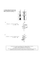
Fig.
21.6
Mechanisms
of
load support
for
hydrodynamic
lubrication,
(a)
Slider
bearing,
(b)
Squeeze
film
bearing,
(c)
Externally pressurized bearing.
Figure
21.6«
shows
a
slider bearing.
For a
positive load
to be
developed
in the
slider bearing shown
in
Fig.
21.6a
the
lubricant
film
thickness must
be
decreasing
in the
direction
of
sliding.
A
squeeze
film
bearing
is
another mechanism
of
load support
of
hydrodynamic
lubrication,
and
it is
illustrated
in
Fig.
21.6b.
The
squeeze action
is the
normal approach
of the
bearing surfaces.
The
squeeze mechanism
of
pressure generation provides
a
valuable cushioning
effect
when
the
bearing
surfaces
tend
to be
pressed together.
Positive
pressures will
be
generated when
the film
thickness
is
diminishing.
An
externally pressurized bearing
is yet a
third mechanism
of
load support
of
hydrodynamic
lubrication,
and it is
illustrated
in
Fig.
21.6c.
The
pressure drop across
the
bearing
is
used
to
support
the
load.
The
load capacity
is
independent
of the
motion
of the
bearing
and the
viscosity
of the
lubricant. There
is no
problem
of
contact
at
starting
and
stopping
as
with
the
other hydrodynamically
lubricated bearings because pressure
is
applied before starting
and is
maintained until
after
stopping.
Hydrodynamically lubricated bearings
are
discussed
further
in
Section 21.2.
Elastohydrodynamic
Lubrication
Regime
Elastohydrodynamic
lubrication
is a
form
of
hydrodynamic lubrication where elastic deformation
of
the
bearing surfaces becomes
significant.
It is
usually associated with highly stressed machine com-
ponents
of low
conformity. There
are two
distinct
forms
of
elastohydrodynamic
lubrication (EHL).
Hard
EHL. Hard
EHL
relates
to
materials
of
high elastic modulus, such
as
metals.
In
this
form
of
lubrication both
the
elastic deformation
and the
pressure-viscosity
effects
are
equally important.
Engineering applications
in
which elastohydrodynamic lubrication
are
important
for
high-elastic-
modulus materials include gears
and
rolling-element bearings.
Soft
EHL.
Soft
EHL
relates
to
materials
of low
elastic
modulus, such
as
rubber.
For
these
materials
the
elastic distortions
are
large, even with light loads. Another feature
of the
elastohydro-
dynamics
of
low-elastic-modulus materials
is the
negligible
effect
of the
relatively
low
pressures
on
the
viscosity
of the
lubricating
fluid.
Engineering applications
in
which elastohydrodynamic lubri-
cation
are
important
for
low-elastic-modulus materials include seals, human joints, tires,
and a
number
of
lubricated
elastomeric
material machine elements.
The
common factors
in
hard
and
soft
EHL are
that
the
local elastic deformation
of the
solids
provides coherent
fluid films and
that asperity interaction
is
largely prevented. Elastohydrodynamic
lubrication normally occurs
in
contacts where
the
minimum
film
thickness
is in the
range
0.1
^m
<
^min
—10
Ann and the film
parameter
A is in the
range
3
<
A < 10.
Elastohydrodynamic lubrication
is
discussed
further
in
Section 21.3.
Boundary
Lubrication
Regime
If
in a
lubricated contact
the
pressures
become
too
high,
the
running speeds
too
low,
or the
surface
roughness
too
great, penetration
of the
lubricant
film
will occur. Contact will take place between
the
asperities.
The
friction will
rise
and
approach that encountered
in dry
friction
between solids. More
importantly, wear will take place. Adding
a
small quantity
of
certain active organic compounds
to
the
lubricating
oil
can, however, extend
the
life
of the
machine elements. These additives
are
present
in
small quantities
(< 1%) and
function
by
forming low-shear-strength surface
films
strongly attached
to the
metal surfaces. Although they
are
sometimes only
one or two
molecules thick, such
films are
able
to
prevent
metal-to-metal
contact.
Some boundary lubricants
are
long-chain molecules with
an
active
end
group, typically
an
alcohol,
an
amine,
or a
fatty
acid. When such
a
material, dissolved
in a
mineral oil, meets
a
metal
or
other
solid surface,
the
active
end
group attaches itself
to the
solid
and
gradually builds
up a
surface layer.
The
surface
films
vary
in
thickness
from
5 X
10~
9
to
10~
8
m
depending
on
molecular size,
and the
film
parameter
A is
less than unity
(A < 1).
Boundary lubrication
is
discussed
further
in
Section
21.4.
Figure 21.7 illustrates
the film
conditions existing
in
hydrodynamic, elastohydrodynamic,
and
boundary
lubrication.
The
surface slopes
in
this
figure are
greatly distorted
for the
purpose
of
illus-
tration.
To
scale, real surfaces would appear
as
gently rolling hills rather than sharp peaks.
21.1.5
Relevant
Equations
This section presents
the
equations
frequently
used
in
hydrodynamic
and
elastohydrodynamic lubri-
cation theory. They
are not
relevant
to
boundary lubrication since
in
this lubrication regime bulk
fluid
effects
are
negligible.
The
differential equation governing
the
pressure distribution
in
hydrodynami-
cally
and
elastohydrodynamically
lubricated machine elements
is
known
as the
Reynolds equation.
For
steady-state
hydrodynamic lubrication
the
Reynolds equation normally appears
as
±f*,*)
+
±
(*,*)
=
,2,,,«*
(21
.
6)
dx
\
dx/
dy
\
dyj
dx
Fig.
21.7
Film conditions
of
lubrication regimes,
(a)
Hydrodynamic
and
elastohydrodynamic
lubrication—surfaces
separated
by
bulk lubricant
film,
(b)
Boundary
lubrication—performance
essentially dependent
on
boundary film.
where
h — film
shape measured
in the z
direction,
m
p
=
pressure,
N/m
2
77
=
lubricant viscosity,
N
sec/m
2
u
=
mean velocity,
(u
a
+
u
b
)/2,
m/sec
Solutions
of Eq.
(21.6)
are
rarely achieved analytically,
and
approximate numerical solutions
are
sought.
For
elastohydrodynamic lubrication
the
steady-state
form
of the
Reynolds equation normally
ap-
pears
as
l/£*\
+±
/£*\
12||
**>
dx
\
T]
dx/
dy
\
T]
dy/
dx
where
p is
lubricant density
in N
sec
2
/m
2
.
The
essential
difference
between Eqs. (21.6)
and
(21.7)
is
that
Eq.
(21.7) allows
for
variation
of
viscosity
and
density
in the
jc
and y
directions. Equations
(21.6)
and
(21.7) allow
for the
bearing surfaces
to be of finite
length
in the y
direction. Side leakage,
or flow in the y
direction,
is
associated with
the
second term
in
Eqs. (21.6)
and
(21.7).
The
solution
of
Eq.
(21.7)
is
considerably more
difficult
than that
of Eq.
(21.6);
therefore, only numerical solutions
are
available.
The
viscosity
of a fluid may be
associated with
the
resistance
to flow,
with
the
resistance arising
from
the
intermolecular
forces
and
internal friction
as the
molecules move past each other. Because
of
the
much larger pressure variation
in the
lubricant conjunction,
the
viscosity
of the
lubricant
for
elastohydrodynamic lubrication does
not
remain constant
as is
approximately true
for
hydrodynamic
lubrication.
As
long
ago as
1893,
Barus
16
proposed
the
following formula
for the
isothermal
viscosity-pressure
dependence
of
liquids:
77
=
W*P
(21.8)
where
T
70
=
viscosity
at
atmospheric pressure
f
=
pressure-viscosity
coefficient
of
lubricant
The
pressure-viscosity
coefficient
£
characterizes
the
liquid considered
and
depends
in
most cases
only
on
temperature,
not on
pressure.
Table
21.2 lists
the
absolute viscosities
of 12
lubricants
at
atmospheric pressure
and
three tem-
peratures
as
obtained
from
Jones
et
al.
17
These values would correspond
to
T
70
to be
used
in Eq.
(21.8)
for the
particular
fluid and
temperature
to be
used.
The 12 fluids
with
manufacturer
and
manufacturer's
designation
are
shown
in
Table 21.3.
The
pressure-viscosity
coefficients
£,
expressed
in
square meters
per
newton,
for
these
12 fluids at
three
different
temperatures
are
shown
in
Table
21.4.
For a
comparable change
in
pressure
the
relative density change
is
smaller
than
the
viscosity
change. However, very high pressures exist
in
elastohydrodynamic
films, and the
liquid
can no
longer
be
considered
as an
incompressible medium. From Dowson
and
Higginson
18
the
density
can be
written
as
/
0.6p
\
'
=
M
1
+
rn^j
(21
-
9)
where
p is
given
in
gigapascals.
Table
21.2
Absolute Viscosities
of
Test Fluids
at
Atmospheric Pressure
and
Three
Temperatures (From Ref.
17)
Temperature,
0
C
_38
99
149
Test
Fluid
Absolute Viscosity,
77,
cP
Advanced ester 25.3 4.75 2.06
Formulated advanced ester 27.6 4.96
2.15
Polyalkyl aromatic 25.5 4.08 1.80
Polyalkyl aromatic
+ 10 wt %
heavy resin 32.2 4.97 2.03
Synthetic
paraffinic
oil
(lot
3) 414
34.3 10.9
Synthetic
paraffinic
oil
(lot
4) 375
34.7 10.1
Synthetic
paraffinic
oil
(lot
4) +
antiwear
additive
375
34.7
10.1
Synthetic
paraffinic
oil
(lot
2) +
antiwear additive
370
32.0 9.93
C-ether 29.5 4.67 2.20
Superrefined
naphthenic mineral
oil
68.1 6.86 2.74
Synthetic hydrocarbon (traction
fluid)
34.3 3.53 1.62
Fluorinated
polyether
181
20.2 6.68
The film
shape appearing
in Eq.
(21.7)
can be
written with
sufficient
accuracy
as
h
=
ho
+
^
+
2R
+
8
^
(2UO)
where
/I
0
=
constant,
m
5(*oO
=
tota
l
elastic
deformation,
m
R
x
=
effective
radius
in x
direction,
m
R
y
=
effective
radius
in y
direction,
m
The
elastic deformation
can be
written,
from
standard elasticity theory,
in the
form
Table
21.3
Fluids with Manufacturer
and
Manufacturer's Designation
(From
Ref.
17)
Test
Fluid Manufacturer Designation
Advanced
ester Shell
Oil Co.
Aeroshell® turbine
oil
555
(base oil)
Formulated advanced ester Shell
Oil Co.
Aeroshell® turbine
oil
555
(WRGL-358)
Polyalkyl aromatic Continental
Oil Co.
DN-600
Synthetic
paraffinic
oil
(lot
3)
Mobil
Oil
Corp.
XRM
109F3
Synthetic
paraffinic
oil
(lot
4) XRM
109F4
Synthetic
paraffinic
oil +
antiwear
XRM
177F2
additive (lot
2)
Synthetic
paraffinic
oil +
antiwear
XRM
177F4
additive (lot
4)
C-ether Monsanto
Co.
MCS-418
Superrefined
naphthenic mineral
oil
Humble
Oil and FN
2961
Refining
Co.
Synthetic
hydrocarbon (traction Monsanto
Co.
MCS-460
fluid)
Fluorinated polyether DuPont
Co. PR 143 AB
(Lot
10)
2 f f
p(x,y)
dx.dy,
^>°
^JI
[(,-W-W"
(2U1)
where
/1
-
v\
1 -
I/A'
1
E'
= 2
——+
——
(21.12)
V^
^b
I
and
v =
Poisson's
ratio
E
=
modulus
of
elasticity,
N/m
2
Therefore,
Eq.
(21.6)
is
normally involved
in
hydrodynamic
lubrication situations, while Eqs.
(21.7)-(21.11)
are
normally involved
in
elastohydrodynamic lubrication situations.
21.2
HYDRODYNAMIC
AND
HYDROSTATIC
LUBRICATION
Surfaces
lubricated
hydrodynamically
are
normally
conformal
as
pointed
out in
Section
21.1.1.
The
conformal
nature
of the
surfaces
can
take
its
form
either
as a
thrust bearing
or as a
journal bearing,
both
of
which will
be
considered
in
this section. Three features must exist
for
hydrodynamic lubri-
cation
to
occur:
1. A
viscous
fluid
must separate
the
lubricated surfaces.
2.
There must
be
relative motion between
the
surfaces.
3. The
geometry
of the film
shape must
be
larger
in the
inlet than
at the
outlet
so
that
a
convergent wedge
of
lubricant
is
formed.
If
feature
2 is
absent, lubrication
can
still
be
achieved
by
establishing relative motion between
the
fluid
and
the
surfaces through external
pressurization.
This
is
discussed
further
in
Section
21.2.3.
In
hydrodynamic lubrication
the
entire
friction
arises
from
the
shearing
of the
lubricant
film so
that
it is
determined
by the
viscosity
of the
oil:
the
thinner
(or
less viscous)
the
oil,
the
lower
the
friction.
The
great advantages
of
hydrodynamic lubrication
are
that
the
friction
can be
very
low
(IJL
=*
0.001)
and,
in the
ideal case, there
is no
wear
of the
moving parts.
The
main problems
in
hydrodynamic lubrication
are
associated with starting
or
stopping since
the oil film
thickness theo-
retically
is
zero when
the
speed
is
zero.
The
emphasis
in
this section
is on
hydrodynamic
and
hydrostatic lubrication. This section
is not
intended
to be all
inclusive
but
rather
to
typify
the
situations existing
in
hydrodynamic
and
hydrostatic
lubrication.
For
additional information
the
reader
is
recommended
to
investigate Gross
et
al.,
19
Reiger,
20
Pinkus
and
Sternlicht,
21
and
Rippel.
22
Table
21.4
Pressure-Viscosity
Coefficients
for
Test
Fluids
at
Three
Temperatures
(From
Ref.
17)
Test
Fluid
Advanced ester
Formulated advanced ester
Polyalkyl
aromatic
Polyalkyl
aromatic
+ 10 wt %
heavy resin
Synthetic
paraffinic
oil
(lot
3)
Synthetic
paraffinic
oil
(lot
4)
Synthetic
paraffinic
oil
(lot
4) +
antiwear
additive
Synthetic
paraffinic
oil
(lot
2) +
antiwear additive
C-ether
Superrefined
naphthenic mineral
oil
Synthetic
hydrocarbon (traction
fluid)
Fluorinated
polyether
Temperature,
0
C
38 99 149
Pressure-viscosity
Coefficient,
f,
m
2
/N
1.28
X
10~
8
0.987
X
10~
8
0.851
X
IO"
8
1.37 1.00 .874
1.58 1.25 1.01
1.70 1.28 1.06
1.77 1.51 1.09
1.99 1.51 1.29
1.96 1.55 1.25
1.81 1.37 1.13
1.80 .980 .795
2.51 1.54 1.27
3.12 1.71 .939
4.17 3.24 3.02