Tài liệu Lecture Notes in Control and Information SciencesEditors: M. Thoma pdf
Bạn đang xem bản rút gọn của tài liệu. Xem và tải ngay bản đầy đủ của tài liệu tại đây (6.38 MB, 201 trang )
Lecture Notes
in Control and Information Sciences 300
Editors: M. Thoma · M. Morari
Springer
Berlin
Heidelberg
NewYork
Hong Kong
London
Milan
Paris
Tokyo
M. Nakamura S. Goto N. Kyura
Mechatronic
Servo System
Control
Problems in Industries
and their Theoretical Solutions
Translated by Tao Zhang
With 79 Figures and 21 Tables
13
Series Advisory Board
A. Bensoussan · P. Fleming · M.J. Grimble · P. Kokotovic ·
A.B. Kurzhanski · H. Kwakernaak · J.N. Tsitsiklis
Authors
Masatoshi Nakamura Satoru Goto
Department of Advanced Systems Department of Advanced Systems
Control Engineering Control Engineering
Saga University Saga University
Japan Japan
Nobuhiro Kyura Translator:
Department of Electrical and Tao Zhang
Communication Engineering Intelligent Systems Research Division
Kyushu School of Engineering National Institute of Informatics
Kinki University Japan
Japan
Translation from the Japanese edition
© Morikita Shuppan Co., Ltd. 1998
All Rights Reserved.
ISSN 0170-8643
ISBN 3-540-21096-2 Springer-Verlag Berlin Heidelberg New York
Library of Congress Control Number: 2004103117
This work is subject to copyright. All rights are reserved, whether the whole or part of the mate-
rial is concerned, specifically the rights of translation, reprinting, reuse of illustrations, recitation,
broadcasting, reproduction on microfilm or in other ways, and storage in data banks. Duplication
of this publication or parts thereof is permitted only under the provisions of the German Copyright
Law of September 9, 1965, in its current version, and permission for use must always be obtained
from Springer-Verlag. Violations are liable for prosecution under German Copyright Law.
Springer-Verlag is a part of Springer Science+Business Media
springeronline.com
© Springer-Verlag Berlin Heidelberg 2004
Printed in Germany
The use of general descriptive names, registered names, trademarks, etc. in this publication does
not imply, even in the absence of a specific statement, that such names are exempt from the relevant
protective laws and regulations and therefore free for general use.
Typesetting: Data conversion by the authors.
Final processing by PTP-Berlin Protago-TeX-Production GmbH, Berlin
Cover-Design: design & production GmbH, Heidelberg
Printed on acid-free paper 62/3020Yu-543210
From theMain Author
As amain author of Mechatronic ServoSystem Control (in Japanese), Iwould
like to express my thanks to Dr. Zhang Taowho translatedour book into
English. The authors, myself, Dr. Goto and Prof. Kyurapublishedthe original
book whichmainly consisted of theauthors’ originalresearchachievement
of mechatronic servosystems control duringlast overten years. Theoriginal
book wasfortunately awarded as thebest book fromthe SocietyofInstrument
andControl Engineering (SICE in Japan) in 2001. Moreover, the book was
alreadytranslatedintoKorea language by aKorean publisher. As the authors
believethatour book is effective forstudents and engineerswho areinvolved
in the field of Mechatronic Controland Robotics, we have been intended
the translationofitinEnglish. The authorsthemselves made the Japanese-
English dictionaryfor theterminologies in the book, andask to Dr. Zhang
Taofor thetranslation of thebookbyuse of thedictionary.Dr. Zhang Tao
hascompletedthe translation by use of his every night times duringlast
severalmonths. Iwould like to showmygreatgratitude forhis effort for the
translation. Ialso express my great thanks to Prof. JeffreyJohnsonand Dr.
MikeRichards(Open UniversityinUK) who helped the final checkofthe
translation.
November 2002 Main author Masatoshi NAKAMURA
From theTranslator
Since the term ”Mechatronics” wasfirst introducedbyaYaskawa Electric en-
gineerin1969, andits rigorous definition wasgiven by atechnical committee,
i.e., The International Federation forthe TheoryofMachinesand Mecha-
nism(IFToMM), as “ Mechatronics is the synergistic combination of precision
mechanical engineering,electronic control, and systemsthinking in design of
productsand manufacturing processes”, the developmentofmechatronic tech-
niques has led to widespread adoption of electronics in machinery.Atthe same
time,asone of thekey techniques of mechatronics, servocontrol system has
been well defined for various kinds of mechanical system.Atpresent, mecha-
tronic techniques areessential for advanced mechanical engineering. Further-
more, the introductionofservocontrol system designtoengineers engaged in
mechanical engineering is thought to be indispensable.
As aresearcher on mechatronic technique, when Ifirstly readthe Japanese
version of this book ”Mechatronic ServoSystem Control”, written by Prof.
Nakamura,Dr. Goto andProf. Kyura,Iwasattracted by its meticulous study
on the issues of mechatronic servocontrol system arisingfrommechanical en-
gineeringaswell as the significance of application. Additionally,Iarouseda
strong desiretotransferits valuable achievements to whole researchersand
engineers who areengaginginthe mechatronic techniques or willingtoob-
tain knowledgerelated with mechatronic techniques. After Iheard that this
book wasawarded the 2001 Works Reward of TheSocietyofInstrument and
Control Engineers (SICE),and Prof. Nakamura alsohad thesame desire to
translate it into other languages forreaders, Iexpressed my strongwish to be
responsible fortranslating thisbookintoEnglish. With deeptrust andgreat
encouragementfromProf. Nakamura,Istarted this challengingprojectfrom
oneyear ago.
Through the great efforts, the English version of ”Mechatronic ServoCon-
trol System” wasfinished recently. As Iread the English version of this book
once again,Ihave alsoobtainedgreatenlightenment fromit, particularly for
my furtherresearchonmechatronic techniques. From thecontentsofthis
book, Ibelieveall readerswill share the same feeling. The profit of this book
VI
II
Fr
om
the
Tr
anslator
will be reflected notonly in the researchorteachingonmechatronic tech-
niques, butalso for engineersworking on mechanical engineering.
Finally, Ialso want to express my great gratitude to Prof. Nakamura,
Dr. Goto andProf. Kyura to distribute suchagreat valuable book on their
achievements within several decades of yearstowhole readers.For thekindly
help from Dr. D. Kushida duringthe periodofmytranslation,especially
the valuable review of this book fromProf. JeffreyJohnsonand Dr. Mike
Richards, Open University ,UK, Itransfermydeep appreciate to them.
Because of my insufficiency of knowledge on translation between Japanese
and
English,
therem
igh
th
ave
some
mistake
si
nt
his
bo
ok.
It
will
be
ve
ry
kind
if
yo
uc
an
indicate
them
to
me
andI
will
mak
em
yb
est
efforts
con
tin
uously
to improve them.
November 2002 TaoZHANG
Preface
The editorand composerisengaginginthe study on systemscontrol and
theirapplicationsinuniversity. As one of his researchfields, with aplenty of
opportunities of discussion with Kyura,who is long-term working on theservo
controller design and its application in mechatronic industry, on thecontrol
of mechatronic machine during the past tenyears, the cooperativeresearch
has been made greatly progress. These discussion meetings were heldseveral
times once ayear. Achievements on the items of these discussion meetings were
compiledintoreports, eachofwhichhas between 50
∼ 100 pages.Then, many
valuable commends were obtained fromKyurainterms of these achievements.
Moreover, new researchdirections were found. The distributionsofco-authors
arethat,
Kyura illustratedthe issuesonthe controlinthe servoparts of an indus-
trial robotadoptedinindustry,numerical control working machine, three-
dimensional measurementmachine,amechatronic machinecalled achip
mounter, etc.;
Nakamura explainedtheseissues in systems control theory and formulized
the obtained crucial points of problem solution;
Goto made computer simulations for the solution of these problems as
well as verifiedthe appropriation of thesedistinct theoretical results by us-
ing mechatr onics-relatedexperimental devices in the laboratory.Inaddition,
amongthe undergraduate students,master students,doctor students who
have interests in the control of mechatronic servosystem, some items were
allocatedtothem andthe relevantachievements were obtained by research
supervision. So far, about60conference presentationsaswell as 20 reviewed
papers on the mechatronic control have been completed.
Based on the above researchstory,the motivation of writingthis book was
written down. Through the question answeringinthe conference forpresenting
the obtained researchachievementordealing with the paper reviewers or the
conversation in thevisiting the universities or researchinstituteswhichare
doing researchonrobot manipulator, we feltstrongly that alot of researchers
XP
reface
or engineershave manymisunderstandingonthe alreadysolved problems in
industry.
In fact,accordingtothe words of coauthor Kyura,the strategiesfor the
encountered problems in the servocontroller designinindustry depending on
theexperien ce with trial errors of designersand engineers arejust responding
to the demandofthe world. These technologieshave notbecome distinct in
the so-called know-howworld.Since they are not logical strategies, even suc-
cessfully performing them, there arestill manycasesthatthe understandable
explanation can notbeobtained. In industry,eventhe clarification of theun-
desiredp
oin
ts
wa
sc
onducted
concretely
,t
he
cont
en
ts
are
not
announced.
It
is
still
in
the
presen
tc
onditiont
hatw
hy
the
go
od
pursuiti
sh
ardly
realized.
Throughthe collab oration,the essence of problems encountered in indus-
try wasanalyzedand formulizedlogicallyand mathematically. Accordingto
the solution of derived equations and the verification of justifiabilityofthese
results, many useful itemswere obtained.Atthe presenttime, these items
are summarized systematically.The opaquetechnologies under the name of
know-howuntil noware explaineddistinctly.Therefore, many researchers or
engineers canknowthem widelyand effectively use them. These are the mo-
tivationofwriting thisbook.
The problems discussed in this book arebase donthe common needs of
industriesrather than thepending problem areasofone researchengineer in
industry.The resultsfor them,whichwere being caughtempirically until now,
are clarified logically.Therefore, the resultsare adaptedfor areal machine,
and various performancesorcontrol methodsofcontroller designpreviously
determinedwith the experience of an expert can noware decidedlogically
basedonthe adopte dresults. Moreover, aknow-howonly suitable forspecial
situations until now, is changed into amorecomplicated andmoreingenious
universal technology.This book is unique in handling these problems.
The organization of this book is that, thedesign of the servocontroller of
mechatronic servosystem is with respect to the fieldsofmodeling, analysis and
controller design control. It is from the introduction to the following chapters
till 7.
In theintroduction, the outlineofmechatronic servosystem and its main
points of the problem in industryare given.
In chapter2,theseproblems aresolved reasonably,whichare the achieve-
ments of cooperativeresearchofco-authors. In eachchapter, main points are
attached.
The presentconditions andproblems in industry,main results, significant
of resultsaswell as the explanation of the main points of applications about
eachitem are conducted at the commencementofeachchapter.
It is acceptable even if thereader reads this book fromthe beginning.For
thereader who wantstolearn with the purpose of understanding, it is also
good to learn eachsection of one chapte rfor dealing with the problems which
arecombinedfromthe problems personallyheld and described in introduction.
In eachsection of eachchapter, main points are inserted at the beginning of
PrefaceX
I
eachsection for recommending the text readingthoroughly.The contents of
eachsection are based on one of authors’ papers whichisspecified with the
quotation article number in the place of the bibliographylist. Finally,the
book contains an index,aglossaryofterms, acollection of symbols anda
description of theexperimental devices used in our experiments.
During preparation, the book wasread with distr ibu tion of sections of this
book by seven master students of dep artmentofadvancedsystems control and
engineering, graduate school of science and engineering, Saga university(Mr.
ShigetoAoki,Mr. TatsuroKatafuchi, Mr. DaisukeKushida,Mr. KentaShira-
masa,M
r.Sho
jiro
Ya
magami,
Mr.M
asashi
Ta
mu
ra,M
r.
Minoru
Nishiza
wa
).
Referringt
ot
heiri
mpressions
of
the
bo
ok,
theb
oo
kw
as
revised
to
impro
ve
readability. The significance of the problems took up it in this book andthe ef-
forts areinmaking the essence of aproblemtothe formula appropriately.The
keys to solution of manyformulas are the easily adopted basis of classicalcon-
trol (Laplacetransformation)ormodern control (differential equation) learnt
with the universitybachelor degree,and the most fundamental knowledge in
the control theory explained in appendix. Therefore, not only the enterprise
directly related with system control or postgraduate students of universityor
researchers,but alsothe undergraduate students with the purpose to makethe
theorylearntinuniversityintopracticecan be expected to read it widely.We
expect that the knowledge obtained from this book can be adoptedwidely in
mechatronic in du stri es, and expect simultaneously that the researchplanted
the root in this kind of ground will be expanded at the researchinstitute etc.
of an enterpriseand, expecially and university.
At the end of the preface, since the materials of this book areall ob-
tained from the cooperativeresearch, the conditions of cooperativeresearch,
thoughts and feelings aroused from the cooperativeresearch, are written as
below, though it mayberedundant.
1. The cooperativeresearcher should be proficientineachfield.
2.
Keep
frequen
td
iscussion
for
al
ongt
ime
among
co
op
erativ
er
esearc
hers.
3. Respect the views of the partner mutually.
4. Fine mutual human relations.
Concerning the writingofthis book, Mr. Kojiro Kobayashi, Department
of productionofthe Morikitapress, andMr. Shoji Ishida,Departmentof
compilationofthe Morikitapress, took careofitvery much.All my great
gratitude arehere expressed.
October 1998 Editor-composer Masatoshi NAKAMURA
1
OutlineofMechatronic ServoSystems
The mechatronic servosystem is the major theme studied in this book. In
particular,the servosystem adopted in an electric servomotor is explainedin
this chapter. Severalitems of its utilization from the developmentstagetothe
presentaswell as its performances. The so-called mechanismmachine (called
as mechatronic servosystem at the following), i.e., the servosystem adopted
in the numerical control machineorindustrialrobot, is generallydifferent
from the servosystem intro du ced in the textbookofautomaticcontrol, which
is very important when discussing the mechatronic servosystem.
Firstly,the control pattern assigned in mechatronic servosystem is illus-
trated.The properties of currentservosystem satisfying the control pattern
and its utilization are introduced. Next, as the discussion items, the analysis
on mechatronic servosystem and its utilization are carried out.
1.1
Emergence
of
Mec
hatronic
Serv
oS
ystems
1.1.1 Control Pattern of Mechatronic Servo Systems
The mechatronic servosystem, as the control system satisfying the motion
conditionsoftransferaxis of numerical control machine, wasoriginally(about
1967) created when developingthe DC servomotor .Then, in 1975 by Yaskawa
Electric,the velocitycontrol equipment(servodriver unit)unifiedthe compen-
satorofcontrol system andpoweramplifier wassold.Initially, it wasmainly
adoptedfor thetransferaxis control of working machine. From 1980, it was
alsoadoptedfor theposition andvelocitycontrols of various kinds of mecha-
nisms suchasthe industrial robot. At the generation of this mechatronic servo
system, the control pattern,asthe startpointofservosystem construction,
is according to the following.
1. The velocityoffset for step-shapetorquedistur bance is below
n [rpm] (gen-
erally below1[rpm]).
M. Nakamura et al.: Mechatronic Servo System Control, LNCIS 300, pp. 1–15, 2004.
Springer-Verlag Berlin Heidelberg 2004
21
Outline
of
Mec
hatronic
Serv
oS
ystems
2. Thevelocitycontrol ratioisone to severalthousands (minimum1[rpm]
and maximum 3000–5000[rpm]).
3. The capabilityofpoweramplifier is effectively adopted (regulationtime
is shortened from the rated currentacceleration/decelerationadoptedfor
limitedvalue) .
Concerning the above three items, their necessityand significantinappli-
cation areintroducedrespectively.Inthe transferaxis of aworking machine,
the pattern is determined from the motionofinstalled in tools forcutting
or rotative cutting. Therehas thecontactofthe blades of thesetools with
proc
essed
prod
uct
andt
he
load
to
transfer
axisa
se
nt
eringt
oo
ls
is
the
motion
friction
torque
added
constan
tly
.W
hen
starting
the
pro
cess,t
here
is
negative
force of processing in the transferaxis installed in tools. Certainly,the degree
of negative force is different fromthe processing state.The negative force con-
ducted at this time can be regarded as thestep-sh apetorqu eload.This torque
load is added as thetorquedisturbance to motorincontrol system.Therefore,
at this time,the velocityoffset is appeared, and the error of processed shape
with designed shapeisgenerated by the transfer axis. Hence, thereexists the
phenomenon of unexpected velocityoffset duetotorquedisturbance.
The second item is necessary when acircular trajectory cannot be ap-
proximatedbyapolygon. In order to realize the circular trajectory,itisvery
difficult to accurately generate analogous sinusoidal or cosine instructions.
Therefore, when generating the circular trajectory,the straight-line command
approx
imating
the
circular
tra
jectory
by
po
lygoni
sg
iv
en
with
considering
the
velocityfor thetwo-axis servosystem constructing aplane. In order to move
with constantspeed along one edge of the polygon, two axesmust move ac-
cording
to
the
ve
lo
cit
yr
atioc
orrespo
nding
to
the
axisi
ncline.A
tt
he
edges
orthogonal between
x axisand y axis, theirvelocityisinfinite. To understand
thiscase easily, the velocitycommandofdriving system causing oneaxis mo-
tion
should
be
needed
fromz
ero
to
infinite
in
theory
.I
nf
act,t
he
edgen
um
be
r
of approximatedpolygon is determinedbythe velo citycontrol ratioofthe
driving system which can actually be implemented.
The
thirdi
tem
is
required
by
op
erational
efficiency
andp
owe
ra
mplifier
economics. The operational efficiency is evaluated by the actual operation
time of the mechanism for an element, for example, the time of mechanism
motionfrombeginningtoend. Therefore, the time without cutting by knifeis
expected to be minimum. Moreover, areduction in the time needed to reach
the constant speed (regulation time of speed) is also attempted. However,
it is notpermittedtocost so much forthis purpose.Ingeneral, the cost
of apoweramplifier is affected greatly by its outputvoltage andpermitted
maximalcurrent. Thus, in the velocitycontrol, it is requiredthatthe power
amplifier is adop tedwith its maximalcapability(allowance current)and the
acceleration/deceleration time is shortened.
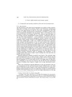
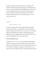
The structure of amechatronic servosystem designed for satisfying these
performancesisillustrated in Fig.1.1 for DC motor. As an aid to understand-
1.1E
mergence
of
Mec
hatronic
Serv
oS
ystems
3
ing the figure, generally,the position control is designed as ratio control and
the velocityaswell as currentminor-loop in its insideisdesigned. Moreover,
in the structure of poweramplifier, PWM amplifier is alwaysadopted. The
carrierfrequencyofbasicwave when usingthis PWM is fromseveral to afew
dozens [kHz] is used.
The structurecomponentofthis mechatronic servosystem is changed from
the originalDCservomotor to an AC servomotor.Moreover, the controller
using position, velocity, currentloopcan be alsochanged into asoftware servo
system with asof tware algorithms using amicro processor, from the original
hardwa
re
computing
amplifier.
1.1.2 Characteristic of Servo SystemApplications
The emergence and structureofmechatronics have been briefly introduced in
the former part. In order to understand that the usage of this mechatronic
servosystem is differentfromthe general servosystem, the main points are
listed as below.
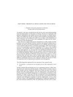
1. In amechatronic servosystem, thereare two typesofcontrol. Oneispo-
sition control (PTP:pointtopoint) emphasizing the arriving time and
stop position from anyposition withoutconsidering the response route.
Anotheristhe contourcontrol (contouring or CP:continuouspath)em-
phasizing the motiontrajectory fromthe current position to thenext
position (positionateachmoment andits motionvelocity). These shapes
are shown in Fig.1.2. The former one is the robot arm for elementassem-
bly,spotwelding, etc, or used for the control of moving axis of mechanism
for drilling ahole.The latter oneisthe armofweldingrobot, painting
robot, laser cuttingrobot, etc, or usedfor thecontrol of transfer axi s
of mechanismimplementing anythree-dimensional shapeprocessing (ma-
chine center, etc).
2. In the contour control, the servosystem, as aposition control system,
requiresstrict velocitycontrol formanykindsofresponse. Concerning
the robot for welding, the importance of velocitycontrol can be easily
K
K ( T s +1)
T s
K ( T s+1)
T s
1
( T s+1)
K
K s+1
1
L s+ R
K
1
J s
1
s
1
N
1
N
K
1
J s
1
s
D
p
i
i aa 1
oaa
τ
M
L
L
L
v
2
a
-
-
1
T s+1
f
v
K
e
s
-
G
G
P o s i t ion
c ontrol p a rt
P o s i t ion
c ontroller
V eloc i ty
c ontrol p a rt
V eloc i ty
c ontroller
C urrent
c ontroller
C urrent
c ontrol p a rt
V eloc i ty
filt e r
A x i s
r e s ona n c e
filt e r
P o w e r
a mplifier
A mplifier
p a rt
M o t o r
M o t o r
elec tri c te r m
T o r q u e
c onsta n t
S p r ing
c onsta n t
M e c h a nis m
p a rt
G e a r
G e a r
Fig. 1.1. Construction of position control system of one-axis mechatronic servo
system
41
Outline
of
Mec
hatronic
Serv
oS
ystems
understood.Inelectric weldingusing an automatic weldingmachine,after
setting voltageand current,the motion velocityofthe torch(the tool
spraying the finesolventcontinuouslyafterturning on thevoltage) is
determinedaccordingtothe heatrate given alongthe curveofweldin g.
Therefore, the motionvelocityofthis torchischanging while the given
heatrate is alsochanging.Ifthe overheat rate is throwninto, themouth
of relevantpartisopened andthe appropriate weldingwhichshould be
with little given heat rate is impossible. In addition, for apainting robot,
if the motionvelocityofpainting canischanged, the spot of painting is
easily
appe
ared.B
esides,
in
the
cuttingo
pe
ration
of
va
rious
materials,
ke
epingt
he
constan
tc
utting
ve
lo
cit
yc
an
guaran
teet
he
cutting
quality
.
3. In thecontourcontrol, an overshoot in theposition control system should
notoccur.Inmanycases, velocitycontrol system is alsoregulated so that
the overshoot cannotoccur.Inthe various kinds of actualprocesses,the
generation of overshoot of position will cause fataldefect of shape. For
example, in the process of constructing ashaft, if an overshoot occurs,
the radiusofthe part becomes smaller, reducingthe strength of this part.
Moreover, if the vibratedtrajectory exists insufficiency of shape, it cannot
be revised at thelatermotion.
4. Theobjectivecommandtoservosystem is obtained correctly before con-
trolinmanycases. It can be said that, the elementsize, setting method,
etc, of operation object of robot or process object of working machine can
be completely known before starting the desiredoperation.Inaddition,
the motion velocityatthis time is alsodefinitely determined.Therefore,
the tract information necessary formotion is knownbefore starting con-
trol. In addition, it can be supposed that external disturbance is mixed
into the control system. When the mixed disturbance overthe supposi-
tion,concerning the safetyofequipment, the motionofcontrol system
should be stopped and the powersource fordriving should be isolated
P
P
P
i
i-1
i+1
x
y
0
Fig. 1.2. PTP control and CP control
1.1E
mergence
of
Mec
hatronic
Serv
oS
ystems
5
as faraspossible.Thatistosay,the motormust be selected from the
clearly discussed results on thenecessary maximaltorquefor executing
op eration.Inaddition, the size of continuouslymixed disturbance must
be belowthe continuous rated torque of motor.
5. In manyservosystems, afeedbacksystem can be only established based
on theinformation of servoactuator, butnot according to the information
of eachmoveable tipormotion tip. It meansthat, the detectorofposition
andvelocityinthe opposite loadside of motor(side without load) is
installed and thenthe feedback system of actuatorcontrol is resembled
by
the
obtained
information.
This
kind
of
con
trol
system
is
called
as
emi-
closed
lo
op.
Generally
,i
ti
sv
ery
difficult
to
construct
the
feedbac
ks
ystem
by motiontip informationinmanymechanism machines. The structureof
afull-closedlooponthe feedback of moveable tipinformation adoptedin
some parts is shown in Fig.1.3. In addition, almost all mechanic structures
of industrial six-freedom degree robots are semi-closed loop. The relation
with servoactuator is briefly shown in Fig.1.4. The structureofthis kind
of semi-closed loop cannotbeobtainedinthe mechatronic servosystem as
same as the general feedbacksystem. Fortaking into account the system
as same as the general feedbacksystem, the condition is that the system
should be rigidlyunifiedwith the actuatorwhen mechanismiswithin the
control region according to the desired motioncommand.
6. Theactuator installed in the mechanism structured for multi-axis move-
able mechanismgenerally corresponds to the forward motionofone actua-
toraswell as rotationofone axis(freedomdegree). The arbitrary curve in
three-dimensional space implemented by simultaneous control of multiple
axes is given in aservosystem as the command of time function about
the position for desired motionineachindependent axis. Theprecondi-
tion in control system is that axisisregarded as independence. In fact,
for example, in the case of amulti-axisrobot arm, th ereactionofone axis
motion affect sother axes, i.e., axis interference occurs. This axis interfer-
ence is very important when tryingtominimize it in mechanism design.
Moreover, in amechatronic servosystem, when considering one axis, the
effect from other axes duetoits reaction is regarded as the disturbance.
D e t e c t o r
Actua t o r M e c h a nis mpa rt
U pper c ontroller
S e rvodr i v e r
Fig. 1.3. Structure of industrial servosystem
61
Outline
of
Mec
hatronic
Serv
oS
ystems
Fig. 1.4. Structure of industrial robot and arrangementofactuator
And forreducing the effect in control to aminimum, the motionofaxis
should be changed as be capable of independence.
7. The generationofobjectivereference input for realizing mechanism move-
mentstructured with amulti-axismechanism is by the servosystem in
whichthe independentmotion of eachaxis includingintroducedmachine
mech
anismc
an
be
realized.
The
featureso
fr
eference
input
is
regulated
for
keepin gthe consistenceofeachaxis. In almost all cases, position control
system is regarded as a1st order system. The feedforward gain should be
iden
tical.
If
regulating
lik
et
his,i
ti
sv
ery
easy
to
implemen
tt
he
algorithm
of referenceinput generation to amulti-axisservosystem for anyspatial
curve.
8.
Fo
rr
ealizing
an
arbitrary
curve
in
three-dimensional
space,
in
most
of
cases,the curveisapproximatedbyafoldedline. As its results, the refer-
ence input to eachaxis servosystem is renewed in eachgiven coordinate
po
in
ta
nd
the
ramp
input
with
va
rious
slop
ea
nglesi
sg
iv
en
con
tin
uously
.
The velocityofeachaxis is calculated for making the given synthetic
velocityasadesiredvelocity. In addition, in the case of performing the
acceleration/deceleration control at start/stop point, the reference input
for simultaneous start/stop of all axes, i.e., same command to eachaxis
at acceleration/decelerationpoint, is generated.
9. Thedata regarded as objective referenceinput to servosystem from the
uppercontrol device, suchascomputerorspecial control, should be given
according to the designatedperiod(designatedtime interval). Therefore,
the
reference
input
for
serv
os
ystem
is
describ
ed
with
the
form
of
av
elo
cit
y
1.2I
ssues
in
Mec
hatronic
Serv
oS
ystems
7
command.Here, the periodofthis commandortime interval is called as
the system clock of theservosystem in the controller or servodata rate of
thecontroller.Since this reference time interval is selected based on the
prop ertyofthe servosystem depend entonthe mechanismpartstructure
and related with the capabilityofcontrol devise, itsvaluerepresents the
synthetic performance of amachine.Inthe numerical control device of
aworking machine, several [ms] as well as ten and several or several ten
times [ms] are adopted.
The knowledge of industrial expects cannot be understood definitely.
Therefore, so far, the theoretical analysi sonthe properties of thecontrol
system
structure,
as
we
ll
as
the
va
rious
prope
rties
of
mech
atronic
serv
os
ys-
tem taking into accountits utilization, as above,cannotbefound. Forthis
purpose ,inthis book, stepping on theutilizationofmechatronic servosystem,
various adoptedcontrol methodsand realizedcontrol performancesbythese
methods are firstly discussedtheoreticallyorarguably as themain point, and
then the discussion on the developmentinthe future is added.
1.2Issues in Mechatronic ServoSystems
In order to understand the current mechatronic servosystem and develop
serv
os
ystems
with
be
tter
pe
rformance
thana
tp
resen
t,
thiss
erv
os
ystem
must be investigated from various points of view. The discussion points are
listed as below.
1. Modelingofamechatronic servosystem
2. Performance of oneaxis in amechatronic servosystem
3. Performance of multiple axes in amechatronic servosystem
4. Command to servosystem
The above viewpoints come from the system components of servosystem
in theory.Itmeans that aservosystem is one of the system components for es-
tablishingamechanism machineand needed to knowthatinwhichstep servo
system can be thoughtasgood enough so that the system is constructed effi-
ciently,desired mechanism as well as performancesisrealized, etc. Therefore,
the description sequence of subsequentchapters is different fromthe expla-
nation sequence in this chapter. Each section is divided by the items listed
above.
1.2.1 Discussion on ModelingofaMechatronicServoSystem
From theview of usingthe model of mechatronic servosystem, this model
should be dividedintotwo points. One is the model with the servosystem not
only taking into accountthe mechanismstructurebut alsothe load.Another
is
the
mo
del
comb
iningt
he
mo
deled
mech
anisms
tructurea
nd
serv
os
ystem.
81
Outline
of
Mec
hatronic
Serv
oS
ystems
Forthe mechanismperf orming orthogonal motion, various discussionscan be
carried out only by the former modeling. But for the machineasanarticulated
robot, the latter modelingisalso necessary.
(1) Modelingofthe Overall MechatronicServoSystem
In the mechatronic servosystem adopted in anymechanism, suchasanumeri-
cal control working machine, industrial robot, etc., representing the industrial
mechanism machine, the propertyofprevious or presentservosystem can be
expressed by K
p
.Ingeneral, the value of K
p
is the high rigid of huge ma-
chine. In the general rotation plate, machinecenter, etc, the value of K
p
is
35–40[1/s]. In an industrial rob ot, the value of K
p
is 15[1/s]. It is naturally
the most simple approximation1st order system in control system. However,
concerning the mechatronic servosystem, it should be considered whichcon-
ditions must be satisfied in its internal structure, and additionally,itisnearly
not clear about the usageconditionofthis 1st order delay system. Actually,if
the maximalspeed used in this machineisabout 1/10 speedregion, this ap-
proximationcan model the whole system quite well. However, if it is number
for one speed, it will have big deviation with theactual system.
In analyzing the currentservosystem, the mechanism is thoughttocom-
bine with shaft of motor whichisasrigid. Under this precondition, the servo
motorfor adriving mechanismisselected. The control parameter regulation
of suchaservosystem is also followingthis consideration.Therefore, the 1st
order approximation with preconditionispursuedtobeclarified
[4
]
.However,
in fact,itisdifficult to satisfy this precondition duetovariousrestraints.
High-speed and high-precision motionofmechatronics machines has been the
objectiveinrecentyears. Forfinding outthe controlstrategy,itisrequired to
mo
del
con
trol
system
correctly
.
Concerning about this problem, it is explained in 2.1 and 2.2.
(2)
Mo
delingo
fa
Multi-Join
tedR
ob
ot
Generally, in the multi-jointed industrial robot, orthogonal motion(in working
coordinate)data is generatedbyusing coordinate calculationbasedoninverse
kinematics.B
yt
he
serv
os
ystem
for
join
ta
ngle
cont
rol(
in
join
tc
oo
rdinate),
the motion can be realizedinworking coordinate system as theorthogonal co-
ordinate system.The inverse kinematics calculation of orthogonal coordinate
va
lue
is
pe
rformeda
te
ac
hr
eference
input
time
in
terv
al.
When given two points for performing orthogonal motion,with high-speed
motion, the phenomenon of deviation of several millimeters in the motion
trajectory of the line between two points is apparent. The motionvelocityof
this time is about 1[m/s]. The reference input time interval of robot controller
is generally adopted with about 20[ms]. This velocityislowerthanthe velocity
of appearing centrifugal force rated with two times velocityfor general issue
or collision ratedwith two axesvelocityintegral. Therefore, the trajectory
1.2I
ssues
in
Mec
hatronic
Serv
oS
ystems
9
deviation is difficulttoconsider basedontheseeffects. But if lengthening the
reference input time interval or whether or not orthogonal motionhappening,
severalreasons should be considered.
When the velocityofpresentcontourcontrol is below25[m /min], the tra-
jectory deviation does notoccur.Therefore, in the controlbasedonthe previ-
ousposition decisioncontrol concept, the trajectory precisioncan be required.
In the position decision control, the motion with the highest velocityallowed
by this robot can be performedinalmost all cases. In the actual examples of
these kindsofapplication,suchashard-cutting,spot-welding, etc, the posi-
tion
va
riation
(tra
jectory
precision)
is
seve
ral[
mm].
Recen
tly
,t
he
follow
ing
is
also
required.
In order to analyze the control strategy for satisfying these requirements,
the correct modelingfor multi-jointed robot is needed. The relevantdetail
description is given in section 2.3.The discussedmodeling combining the
modelingofthe whole servosystem in the former part, the importance of
modelingcontrol system in future mechanis mmachinesisillustrated.
1.2.2Discussion on the Performance of One AxisinaMechatronic
ServoSystem
In ausual, mechatronic servosystem consists of multi-axis mechanism. When
taking into accountthe performance of amechanism machine, the analysis
on
mu
lti-axis
serv
os
ystem
mu
st
be
carried
out.
Ho
we
ve
r,
the
structure
for
thisactuator is basically independentfor oneaxis. Forthe basicfeature of
amechatronic servosystem, the discussion based on the state of one axis
structurei
ss
ufficient
.
Hence, thereare two problems on discrete time interval when analyzing the
oneaxis performance of mechatronic servosystem. One is that the structureof
curren
tm
ec
hatronic serv
os
ystems
are
almost
all
soft
wa
re
serv
os
ystems
and
they must be thoughtofcoming fromthe sampling controlsystems. Therefore,
the data renewal time interval of control system is determined by sampling
frequency
.I
ng
eneral
mec
hatronic
serv
os
ystem,
theree
xist
same
dela
yt
ime
and 0th order hold with this time interval. Therefore, this time interval greatly
affects the characteristicofclosed-loop control system.
Another is that, the uppercontroller seen fromthe servosystem, i.e., the
computerusing for internal trajectory calculationofthe controller, is per-
formedinatime interval providingcommandgiven in the servosystem. From
therelationbetween this time interval and performance of thecontrol system,
theoverall mechatronic servosystem performance of amechatronic machine
can be determined. From this pointofview, the value of these discrete time
intervals are very important foranalyzing the performance of amechatronic
servosystem.
10
1O
utline
of
Mec
hatronic
Serv
oS
ystems
(1)Proper Sampling Frequency
In themiddle of 1980s, microprocessor (CPU), i.e., digital signal processor
(DSP)became cheaper. These processors are equippedintoclosed-loop of
servosystem. Hence, servosystem is constructed and movementcan be re-
markably flexible. Software servosystems were developed.
Theseservosystems were developed in thelaboratorybelonging to one of
authors. From theexperiments, an experience rule, wasobtained. The eigen-
value of position control system usingfor amechatronic machinebasedonthe
realizedsoftware servofromthe analoguevelocityofacontrol device cannot
be overabout 1/30 sampling frequency. Moreover, the velocitycontrol system
is madebythe software servosystem and its insidecan be found similarwith
the analogue pattern.
The great difference herebetween the general sampling control system and
the control system used in the mechanism machineisthe delay time. In the
usually equippedprocess control, comparing with the sampling time interval,
thecon sumedtime for working outthe state in put andoperation value can be
neglected. However, in the servosystem of amechanism machine, this cannot
be successful.
If the software servosystem adopted in amechanism machineisthe object
of simulation, various unknown parts areclosed up.How to set the prop erty
of poweramplifier with PWM pattern,and howtocatchthe timing of state
input andthe dynamicofoperation output canbeobtained.
In general, in asoftware servosystem, avery big sampling frequency is
adopted.Namely,under the restraintofhardwarecost,the maximalsampling
frequencyisselected.Indetermining the sampling frequency by this way,the
performance boundary of theservosystem when usingthis frequencyisnot
distinct.Eventhoughexpecting to raise its performance,whichcomponentof
control system should be improvedisalso unknown.
In section 3.1,the quite simpleformofmechatronic servosystem wasana-
lyzed. The relation between the performance of acontrol system andsampling
time interval when considering the utilization situation of aservosystem was
clarified.
(2) Reference Input Time Interval
When considering the characteristicofamechatronic servosystem as intro-
duced before, andregarding the loop structureofacontrol system about
actuator above investigation of servosystem characteristicasthe identical
importantitem with its controller design, howtoprovide the commandto
servosystem is aproblem. Thisproblemisabout the form of time functionof
command.The problemofcommandcontaining the way of data given must
be discussed.
In the discussion of this commandsystem, with the currentcontroller
structure, as th eitem about the control performance of aservosystem, the
1.2I
ssues
in
Mec
hatronic
Serv
oS
ystems
11
time intervalofgiven data to the servosystem through the interface from the
uppercontroller is expected. Generally,inthe controller of themechanism
machine, the data to the servosystem is given in adesignated period. This
designatedperiodiscalled thereference input time interval. This is also called
the (controller) system clock.
This reference input time interval is discrete width as the data to the servo
system. Within this interval, the command function of eachaxis is calculated.
Then,this calculatedvalueisobtainedinthe servosystem with the state of
zero order hold. From this,the motion of theservosystem generates velocity
pe
rio
dic
va
riation
reliedo
nt
his
time
in
terv
al
andt
ra
jectory
deterioration.
Previously,
the
reference
input
time
in
terv
al
is
obtained
as
the
va
lue
rep-
resenting the controller performance.Atpresent, in the newly develop ed con-
troller,this value has the trendtobeminimal. However, dominatedbythe
development of themicroprocessor, the desired performance is expected to
be realizedwithout great cost. Therefore, the reasonable explanation of the
relationship between this reference input time interval and various generated
phenomenonisalmost non-existent.
The competition of mechatronic product cost is rapidlyincreased. High
performance is requiredmeanwhile keepingthe current situation. In this sit-
uation, the performance of servodriver unit,the performance of theupper
controller (reference input time interval, etc) as well as the characteristicof
loadare analyzedcomprehensively.Bytaking these performancesobtained
the balance whenobserving these performancesrespectively as the whole, it
is very important to realize these desired performancescomprehensively.As
the first stagefor analyzing them, fromthe view of theservosystem char-
acteristicofone axis, thediscussion on the reference input time interval is
carried out in section 3.2 and 3.3.
(3) Quantization Error and ControlPerformance of Control
System
Thestructureofthe software servosystem wasdeveloped from only the po-
sition controller software to both velocitycontroller andcurrentcontroller
software, fromthe development of utilizedCPS, i.e.,DSP.Inthe construction
of thecontrol system,high response performance is generallyrequired from its
internal minor-loop. In the electric servosystem, currentfeedbackloopisthe
inner-most loop.How resolution of currentdetection is expected for satisfying
the required performance of servosystem is an important item to discuss in
the stageofdesigning hardware constructing servosystem.
As usual, although the control performancesabout the position and veloc-
ityofthe servosystem were clear, the theoretical equationsfor expressing the
designwhichthe controlperformance must be satisfied about its internal is
unknown. In view of theconcretecircuit structure, the discussion of the item
on quantizationerrorisformulated. However, the analysissolution on various
in
ternalp
arameters
relation
to
thec
on
trol
system
structure
is
ve
ry
difficult
12
1O
utline
of
Mec
hatronic
Serv
oS
ystems
to solve. Its difficulty would be estimated by taking into accountthe equation
expression of poweramplifier of PWM pattern.Fromthis pointofview, in
almost all presentcases, thequantizationscale of control system internal, i.e.,
resolution is determined based on experience.
Here, for the current(torque) loop of the motor, the most internal loop
of mechatronic servosystem, the relationship between the necessary perfor-
mance in the controlsystem and the resolution of currentdetection part is
investigated. In order to clarify the main issue on considering the current
structureofthe mechatronic servosystem, the foreseen whole control system
is
considered
and
the
problems
are
form
ulated.
On
these
problems,
is
discussed
in
ch
apter4
,a
ftera
nalyzing
the
resolution
of position detection firstly in section 4.1,the torque resolution is investigated
in section 4.2.Fromthe formulation illustratedhere, the resolution of torque
command considering velocityvariation ratioasacontrol performance is clear.
According to thisresult, the necessityofidenticalprecisionwith the necessary
resolution in currentdetection is clear. Moreover, in the case of zero-zoneof
poweramplifier, i.e., nonlinear characteristic, it is easytoevaluate that the
high resolution is necessary from the obtained results here.
1.2.3Discussion on the Performance of aMulti-AxisMechatronic
Servo System
The
basic
part
of
on
discussion
on
mec
hatronic
serv
os
ystems
can
be
carried
out as aone-axisservosystem. However, wheninvestigatingthe performance
of mechanismmachines, theymust be investigated as multiple axes. The mo-
tion
of
mu
lti-axis
serv
os
ystems
causing
basic
phenomena
duet
ot
orques
at-
uration can be found. Whenusing aservosystem in the state of one axis,
thereisalmost no problem in the induced phenomenon duetotorquesat-
uration
fromt
he
serv
os
ystem
pe
rformance
po
in
to
fv
iew.
Ho
we
ve
r,
if
this
phenomenon occursinthe multi-axis contour control, it will produce great
effects on servosystem performance.Theseproblems arediscussed in section
5.1
and
5.2.
(1)
To
rque
Saturation
Generally,
in
mec
hatronic
serv
os
ystems,
the
ratio
of
maximalt
orquet
hatc
an
be usedinratedtorqueand acceleration/deceleration is about1:3∼ 5. In actual
servosystems, constantcoulombfriction frommotion resistance occupies a
big part of rated torque when the servosystem is set into the mechanism. It
means that, the opposite force in operation is regarded as the torque load.
In order to allowthesetorques in thecontrol system when performing the
movementalong astraightline, their values are reduced remarkably.Hence,
in contour control, the servosystem must guarantee themovementalong the
straightline. When clarifyingthe application conditionofthe mechatronic
system,i
tm
ust
grasp
that
in
whic
hs
cale
torque
reac
hes
saturationi
nt
he
1.2I
ssues
in
Mec
hatronic
Serv
oS
ystems
13
state of capable motionofthe mechanis maswell as in whichdegree control
performance deterioratesdue to torque saturation.
Themechatronic servosystem design should select aservomotor forthe
driving mechanisminmanycasesexcept the stageofresearch. Therefore, in
servomotor selection,the velocityprofile (stage form) fordriving is designed
andacceleration/decelerationaswell as constantmotion torquefor designated
parameters (acceleration time,maximal velocity, etc) are calculated. In the
mechatronic servosystem driven by the motorselected as above,itisalmost
impossible to consider clearly the torque reflecting the actual adopted status.
In
section
5.1,fi
rstly
,t
he
measuremen
tm
etho
do
ft
orques
aturation
is
show
n.
Basedo
nt
his
metho
d,
the
torque
saturation
of
thea
ctual
mec
hanism
with the differentstatuses of asingle motorcan be known. Moreover, from
graspingthe occurred phenomenon when existing torque saturationasinthe
ab ove illustration, the reason of actual phenomena can be definitely judged.
Foravoidingtorquesaturation naturally, the actuatorcapable of exporting
torque with big capacity is needed to use. In reality, the correct motionis
more importantthanchanging the application method.For this purpose,itis
necessary to knowthe simpleavoidance method, whichisdiscussed in section
5.2.
(2) Master-Slave Synchronous PositioningControl
Them
aster-sla
ve
sync
hronous
po
sitioning
con
trol
metho
di
st
he
cont
rolt
hat
must satisfy the ratio relationbetween the movementofone axisand that
of another axisbetween two axes. This control is generatedfromthe motion
pe
rformance
requiredi
nt
he
tapping
pro
cess
of
them
ac
hining
cent
er.
In
the
tappingprocess,the 1st axisisthe master axisofthe machiningcenter. This
axis is moving as the control system performing startand stop forstageform
driving
installed
in
the
rotational
to
ols.T
he
transfera
xis
as
the
second
axis
should be traced, namely synchronized. So then it performs aparallel move-
mentasaposition control part. When the tapper, atoolfor standing tap
forr
otation
mo
ve
men
tk
ept
in
the
master
axis,
is
rotated
once,
the
transfer
axis must be movedcorrectone pitch of thespring.Since this correct motion
cannot be guaranteed,the tool calledasoft-tapp er is used to keep the tap-
perthroughthe spring andthe synchronous errorofrotation andtransferis
absorbed.
However, since thissoft-tapperisvery expensive, for the decrease of run-
ningcost fortapping,high-precision master-slave synchronous positioning
control is demanded. In themiddle of the 1980s, not only wasthe present
soft-tapper adopted, but alsothe general tapping process wasrealized. At
this time, the rotationtimes of master axis is from 3000 to 4000[rpm].
In order to improve productioninthe future,high-speed master axis ro-
tationnumberisdemanded .For therelevanthigh-level spring, high-p recision
master-slave synchronous positioning control is required as well. The relevant
14
1O
utline
of
Mec
hatronic
Serv
oS
ystems
discussion is carriedout in section7.1. In addition, the possibilityofadapt-
ing thismaster-slave synchronous positioningcontrol in contourcontrol is
explainedinsection 7.2.
1.2.4 Discussion on the CommandofMechatronic Servo Systems
Forimproving the motionperformance of the whole mechatronic servosystem,
the methodfor providing the commandtothe servosystem at eachmoment
is avery importantfactor.Itmeans that the final desired motionofcurrent
mechatr onic servosystems should be approximatedfromthe known informa-
tion before the beginning of control. As thepreconditionofuse state of present
servosystem, the revision methodfor theknown commandfor realizing the
desiredmotion is analyzedinchapter6.
(1) Modified TaughtData Method
The contour control for athree-dimensional curveinthe presentindustrial
robot, the curve is approximated by afolded line. In the contourcontrol, the
locus(position) as the form and its motionspeed are the important control
parameters. As usual, the ramp input with adesignated slopefor eachaxis
as its command is introduced.
In
suc
ha
kind
of
rob
ot
pe
rforming
thisc
on
trol,
when
giv
en
three
po
in
ts
and angles are describ ed by aline trajectory,atthe corner part, the trajec-
tory
deviatesf
romt
he
corner
po
in
td
ep
ending
on
the
ve
lo
cit
y.
Certainly
,t
he
ve
lo
cit
yi
sa
lso
decreased.
Fo
rd
ealing
with
this
kind
of
situation,
skilled
op-
eratorofteachingissuccessfully carriedout by given taughtdata variedfrom
the
finaln
eeded
shap
ef
or
eliminating
the
deviation
fromt
he
corner
po
in
ti
n
con
tin
uous
motion.
This
metho
di
si
llustrated
concretely
for
realizing
desired
motionbyrevising commandstoservosystem.
When
approx
imating
ar
ob
ot
armb
ya
1st
order
delay
system
and
assum-
ing
it
as
an
orthogonal
co
ordinate
rob
ot,
concerningt
he
quite
long
straight
line, the theoretical explanation of this phenomenon realizing skilled operator
can
be
easily
carried
out.
Ho
we
ve
r,
it
is
kno
wn
thatt
his
metho
di
sa
lmost
im-
po
ssible
by
the
ab
ove
form
ulation
when
it
is
adoptedf
or
theg
eneral
mu
lti-axis
mechatronic servosystem.
In
sections
6.1,6
.2
and
6.3,t
he
solutiono
ft
he
metho
df
or
impro
ving
the
effective motionperformance by the taughtpointwhichisacircular trajec-
tory butnot lineartrajectory,namely thecomposedtrajectory is given.Here,
taking the taughtpointinformation as thedesired final robot motion, the
analysis solutionfor theissue, that howthe taught pointinformation is re-
visedtobegiven in aservosystem so that the desired motioncan be desired,
is illustrated. The flowchartisexpected to rememberthe solutionwhose roots
must be definitely usedinamechatronic servosystem.
The command methodadoptedinthis book is notonly introducedin
this
ch
apter,
but
alsoc
onsideredf
or
thep
erformance
improve
men
to
ft
he