Tài liệu What is a PLC Starters pdf
Bạn đang xem bản rút gọn của tài liệu. Xem và tải ngay bản đầy đủ của tài liệu tại đây (627.63 KB, 68 trang )
Starters
What is a PLC?
A PLC (i.e. Programmable Logic Controller) is a device that was invented to replace the
necessary sequential relay circuits for machine control. The PLC works by looking at its inputs
and depending upon their state, turning on/off its outputs. The user enters a program, usually via
software, that gives the desired results.
PLCs are used in many "real world" applications. If there is industry present, chances are good
that there is a plc present. If you are involved in machining, packaging, material handling,
automated assembly or countless other industries you are probably already using them. If you are
not, you are wasting money and time. Almost any application that needs some type of electrical
control has a need for a plc.
For example, let's assume that when a switch turns on we want to turn a solenoid on for 5
seconds and then turn it off regardless of how long the switch is on for. We can do this with a
simple external timer. But what if the process included 10 switches and solenoids? We would
need 10 external timers. What if the process also needed to count how many times the switches
individually turned on? We need a lot of external counters.
As you can see the bigger the process the more of a need we have for a PLC. We can simply
program the PLC to count its inputs and turn the solenoids on for the specified time.
This site gives you enough information to be able to write programs far more complicated than
the simple one above. We will take a look at what is considered to be the "top 20" plc instructions.
It can be safely estimated that with a firm understanding of these instructions one can solve more
than 80% of the applications in existence.
That's right, more than 80%! Of course we'll learn more than just these instructions to help you
solve almost ALL your potential plc applications.
PLC History
In the late 1960's PLCs were first introduced. The primary reason for designing such a device
was eliminating the large cost involved in replacing the complicated relay based machine control
systems. Bedford Associates (Bedford, MA) proposed something called a Modular Digital
Controller (MODICON) to a major US car manufacturer. Other companies at the time proposed
computer based schemes, one of which was based upon the PDP-8. The MODICON 084 brought
the world's first PLC into commercial production.
When production requirements changed so did the control system. This becomes very expensive
when the change is frequent. Since relays are mechanical devices they also have a limited
lifetime which required strict adhesion to maintenance schedules. Troubleshooting was also quite
tedious when so many relays are involved. Now picture a machine control panel that included
many, possibly hundreds or thousands, of individual relays. The size could be mind boggling.
How about the complicated initial wiring of so many individual devices! These relays would be
individually wired together in a manner that would yield the desired outcome. Were there
problems? You bet!
These "new controllers" also had to be easily programmed by maintenance and plant engineers.
The lifetime had to be long and programming changes easily performed. They also had to survive
the harsh industrial environment. That's a lot to ask! The answers were to use a programming
technique most people were already familiar with and replace mechanical parts with solid-state
ones.
In the mid70's the dominant PLC technologies were sequencer state-machines and the bit-slice
based CPU. The AMD 2901 and 2903 were quite popular in Modicon and A-B PLCs.
Conventional microprocessors lacked the power to quickly solve PLC logic in all but the smallest
PLCs. As conventional microprocessors evolved, larger and larger PLCs were being based upon
them. However, even today some are still based upon the 2903.(ref A-B's PLC-3) Modicon has
yet to build a faster PLC than their 984A/B/X which was based upon the 2901.
Communications abilities began to appear in approximately 1973. The first such system was
Modicon's Modbus. The PLC could now talk to other PLCs and they could be far away from the
actual machine they were controlling. They could also now be used to send and receive varying
voltages to allow them to enter the analog world. Unfortunately, the lack of standardization
coupled with continually changing technology has made PLC communications a nightmare of
incompatible protocols and physical networks. Still, it was a great decade for the PLC!
The 80's saw an attempt to standardize communications with General Motor's manufacturing
automation protocol(MAP). It was also a time for reducing the size of the PLC and making them
software programmable through symbolic programming on personal computers instead of
dedicated programming terminals or handheld programmers. Today the world's smallest PLC is
about the size of a single control relay!
The 90's have seen a gradual reduction in the introduction of new protocols, and the
modernization of the physical layers of some of the more popular protocols that survived the
1980's. The latest standard (IEC 1131-3) has tried to merge plc programming languages under
one international standard. We now have PLCs that are programmable in function block
diagrams, instruction lists, C and structured text all at the same time! PC's are also being used to
replace PLCs in some applications. The original company who commissioned the MODICON 084
has actually switched to a PC based control system.
Theory of Operation
The Internal
The PLC mainly consists of a CPU, memory areas, and appropriate circuits to receive
input/output data. We can actually consider the PLC to be a box full of hundreds or thousands of
separate relays, counters, timers and data storage locations. Do these counters, timers, etc.
really exist? No, they don't "physically" exist but rather they are simulated and can be considered
software counters, timers, etc. These internal relays are simulated through bit locations in
registers. (more on that later)
What does each part do?
• INPUT RELAYS-(contacts)These are connected to the outside world. They physically
exist and receive signals from switches, sensors, etc. Typically they are not relays but
rather they are transistors.
• INTERNAL UTILITY RELAYS-(contacts) These do not receive signals from the outside
world nor do they physically exist. They are simulated relays and are what enables a PLC
to eliminate external relays. There are also some special relays that are dedicated to
performing only one task. Some are always on while some are always off. Some are on
only once during power-on and are typically used for initializing data that was stored.
• COUNTERS-These again do not physically exist. They are simulated counters and they
can be programmed to count pulses. Typically these counters can count up, down or both
up and down. Since they are simulated they are limited in their counting speed. Some
manufacturers also include high-speed counters that are hardware based. We can think
of these as physically existing. Most times these counters can count up, down or up and
down.
• TIMERS-These also do not physically exist. They come in many varieties and
increments. The most common type is an on-delay type. Others include off-delay and
both retentive and non-retentive types. Increments vary from 1ms through 1s.
• OUTPUT RELAYS-(coils)These are connected to the outside world. They physically exist
and send on/off signals to solenoids, lights, etc. They can be transistors, relays, or triacs
depending upon the model chosen.
• DATA STORAGE-Typically there are registers assigned to simply store data. They are
usually used as temporary storage for math or data manipulation. They can also typically
be used to store data when power is removed from the PLC. Upon power-up they will still
have the same contents as before power was removed. Very convenient and necessary!!
How it works - PLC Operation
A PLC works by continually scanning a program. We can think of this scan cycle as consisting
of 3 important steps. There are typically more than 3 but we can focus on the important parts and
not worry about the others. Typically the others are checking the system and updating the current
internal counter and timer values.
Step 1-CHECK INPUT STATUS-First the PLC takes a look at each input to determine if it is on or
off. In other words, is the sensor connected to the first input on? How about the second input?
How about the third It records this data into its memory to be used during the next step.
Step 2-EXECUTE PROGRAM-Next the PLC executes your program one instruction at a time.
Maybe your program said that if the first input was on then it should turn on the first output. Since
it already knows which inputs are on/off from the previous step it will be able to decide whether
the first output should be turned on based on the state of the first input. It will store the execution
results for use later during the next step.
Step 3-UPDATE OUTPUT STATUS-Finally the PLC updates the status of the outputs. It updates
the outputs based on which inputs were on during the first step and the results of executing your
program during the second step. Based on the example in step 2 it would now turn on the first
output because the first input was on and your program said to turn on the first output when this
condition is true.
After the third step the PLC goes back to step one and repeats the steps continuously. One scan
time is defined as the time it takes to execute the 3 steps listed above.
Response Time
The total response time of the PLC is a fact we have to consider when shopping for a PLC. Just
like our brains, the PLC takes a certain amount of time to react to changes. In many applications
speed is not a concern, in others though
If you take a moment to look away from this text you might see a picture on the wall. Your eyes
actually see the picture before your brain says "Oh, there's a picture on the wall". In this example
your eyes can be considered the sensor. The eyes are connected to the input circuit of your brain.
The input circuit of your brain takes a certain amount of time to realize that your eyes saw
something. (If you have been drinking alcohol this input response time would be longer!)
Eventually your brain realizes that the eyes have seen something and it processes the data. It
then sends an output signal to your mouth. Your mouth receives this data and begins to respond
to it. Eventually your mouth utters the words "Gee, that's a really ugly picture!".
Notice in this example we had to respond to 3 things:
INPUT- It took a certain amount of time for the brain to notice the input signal
from the eyes.
EXECUTION- It took a certain amount of time to process the information
received from the eyes. Consider the program to be: If the eyes see an ugly
picture then output appropriate words to the mouth.
OUTPUT- The mouth receives a signal from the brain and eventually spits (no
pun intended) out the words "Gee, that's a really ugly picture!"
Response Time Concerns
Now that we know about response time, here's what it really means to the application. The PLC
can only see an input turn on/off when it's looking. In other words, it only looks at its inputs during
the check input status part of the scan.
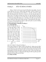
In the diagram, input 1 is not seen until scan 2. This is because when input 1 turned on, scan 1
had already finished looking at the inputs.
Input 2 is not seen until scan 3. This is also because when the input turned on scan 2 had already
finished looking at the inputs.
Input 3 is never seen. This is because when scan 3 was looking at the inputs, signal 3 was not on
yet. It turns off before scan 4 looks at the inputs. Therefore signal 3 is never seen by the plc.
To avoid this we say that the input should be on
for at least 1 input delay time + one scan time.
But what if it was not possible for the input to be on this long? Then the plc doesn't see the input
turn on. Therefore it becomes a paper weight! Not true of course there must be a way to get
around this. Actually there are 2 ways.
Pulse stretch function. This function extends the length
of the input signal until the plc looks at the inputs during
the next scan.( i.e. it stretches the duration of the pulse.)
Interrupt function. This function interrupts the scan to
process a special routine that you have written. i.e. As
soon as the input turns on, regardless of where the scan
currently is, the plc immediately stops what its doing and
executes an interrupt routine. (A routine can be thought
of as a mini program outside of the main program.) After
its done executing the interrupt routine, it goes back to
the point it left off at and continues on with the normal
scan process.
Now let's consider the longest time for an output to actually turn on. Let's assume that when a
switch turns on we need to turn on a load connected to the plc output.
The diagram below shows the longest delay (worst case because the input is not seen until scan
2) for the output to turn on after the input has turned on.
The maximum delay is thus 2 scan cycles - 1 input delay time.
It's not so difficult, now is it ?
Creating Programs
Relays
Now that we understand how the PLC processes inputs, outputs, and the actual program we are
almost ready to start writing a program. But first lets see how a relay actually works. After all, the
main purpose of a plc is to replace "real-world" relays.
We can think of a relay as an electromagnetic switch. Apply a voltage to the coil and a magnetic
field is generated. This magnetic field sucks the contacts of the relay in, causing them to make a
connection. These contacts can be considered to be a switch. They allow current to flow between
2 points thereby closing the circuit.
Let's consider the following example. Here we simply turn on a bell (Lunch time!) whenever a
switch is closed. We have 3 real-world parts. A switch, a relay and a bell. Whenever the switch
closes we apply a current to a bell causing it to sound.
Notice in the picture that we have 2 separate circuits. The bottom(blue) indicates the DC part. The
top(red) indicates the AC part.
Here we are using a dc relay to control an AC circuit. That's the fun of relays! When the switch is
open no current can flow through the coil of the relay. As soon as the switch is closed, however,
current runs through the coil causing a magnetic field to build up. This magnetic field causes the
contacts of the relay to close. Now AC current flows through the bell and we hear it. Lunch time!
A typical industrial relay
Replacing Relays
Next, lets use a plc in place of the relay. (Note that this might not be very cost effective for this
application but it does demonstrate the basics we need.) The first thing that's necessary is to
create what's called a ladder diagram. After seeing a few of these it will become obvious why its
called a ladder diagram. We have to create one of these because, unfortunately, a plc doesn't
understand a schematic diagram. It only recognizes code. Fortunately most PLCs have software
which convert ladder diagrams into code. This shields us from actually learning the plc's code.
First step- We have to translate all of the items we're using into symbols the plc understands.
The plc doesn't understand terms like switch, relay, bell, etc. It prefers input, output, coil, contact,
etc. It doesn't care what the actual input or output device actually is. It only cares that its an input
or an output.
First we replace the battery with a symbol. This symbol is common to all ladder diagrams. We
draw what are called bus bars. These simply look like two vertical bars. One on each side of the
diagram. Think of the left one as being + voltage and the right one as being ground. Further think
of the current (logic) flow as being from left to right.
Next we give the inputs a symbol. In this basic example we have one real world input. (i.e. the
switch) We give the input that the switch will be connected to, to the symbol shown below. This
symbol can also be used as the contact of a relay.
A contact symbol
Next we give the outputs a symbol. In this example we use one output (i.e. the bell). We give the
output that the bell will be physically connected to the symbol shown below. This symbol is used
as the coil of a relay.
A coil symbol
The AC supply is an external supply so we don't put it in our ladder. The plc only cares about
which output it turns on and not what's physically connected to it.
Second step- We must tell the plc where everything is located. In other words we have to give all
the devices an address. Where is the switch going to be physically connected to the plc? How
about the bell? We start with a blank road map in the PLCs town and give each item an address.
Could you find your friends if you didn't know their address? You know they live in the same town
but which house? The plc town has a lot of houses (inputs and outputs) but we have to figure out
who lives where (what device is connected where). We'll get further into the addressing scheme
later. The plc manufacturers each do it a different way! For now let's say that our input will be
called "0000". The output will be called "500".
Final step- We have to convert the schematic into a logical sequence of events. This is much
easier than it sounds. The program we're going to write tells the plc what to do when certain
events take place. In our example we have to tell the plc what to do when the operator turns on
the switch. Obviously we want the bell to sound but the plc doesn't know that. It's a pretty stupid
device, isn't it!
The picture above is the final converted diagram. Notice that we eliminated the real world relay
from needing a symbol. It's actually "inferred" from the diagram. Huh? Don't worry, you'll see what
we mean as we do more examples.
Basic Instructions
Now let's examine some of the basic instructions is greater detail to see more
about what each one does.
Load
The load (LD) instruction is a normally open contact. It is sometimes also called examine if on.
(XIO) (as in examine the input to see if its physically on) The symbol for a load instruction is
shown below.
A LoaD (contact) symbol
This is used when an input signal is needed to be present for the symbol to turn on. When the
physical input is on we can say that the instruction is True. We examine the input for an on signal.
If the input is physically on then the symbol is on. An on condition is also referred to as a logic 1
state.
This symbol normally can be used for internal inputs, external inputs and external output
contacts. Remember that internal relays don't physically exist. They are simulated (software)
relays.
LoadBar
The LoaDBar instruction is a normally closed contact. It is sometimes also called LoaDNot or
examine if closed. (XIC) (as in examine the input to see if its physically closed) The symbol for a
loadbar instruction is shown below.
A LoaDNot (normally closed contact) symbol
This is used when an input signal does not need to be present for the symbol to turn on. When
the physical input is off we can say that the instruction is True. We examine the input for an off
signal. If the input is physically off then the symbol is on. An off condition is also referred to as a
logic 0 state.
This symbol normally can be used for internal inputs, external inputs and sometimes, external
output contacts. Remember again that internal relays don't physically exist. They are simulated
(software) relays. It is the exact opposite of the Load instruction.
*NOTE- With most PLCs this instruction (Load or Loadbar) MUST be the first symbol on the left of
the ladder.
Logic State Load LoadBar
0 False True
1 True False
Out
The Out instruction is sometimes also called an OutputEnergize instruction. The output instruction
is like a relay coil. Its symbol looks as shown below.
An OUT (coil) symbol
When there is a path of True instructions preceding this on the ladder rung, it will also be True.
When the instruction is True it is physically On. We can think of this instruction as a normally open
output. This instruction can be used for internal coils and external outputs.
Outbar
The Outbar instruction is sometimes also called an OutNot instruction. Some vendors don't have
this instruction. The outbar instruction is like a normally closed relay coil. Its symbol looks like that
shown below.
An OUTBar (normally closed coil) symbol
When there is a path of False instructions preceding this on the ladder rung, it will be True. When
the instruction is True it is physically On. We can think of this instruction as a normally closed
output. This instruction can be used for internal coils and external outputs. It is the exact opposite
of the Out instruction.
Logic State Out OutBar
0 False True
1 True False
A Simple Example
N ow let's compare a simple ladder diagram with its real world external physically connected
relay circuit and SEE the differences.
In the above circuit, the coil will be energized when there is a closed loop between the + and -
terminals of the battery. We can simulate this same circuit with a ladder diagram. A ladder
diagram consists of individual rungs just like on a real ladder. Each rung must contain one or
more inputs and one or more outputs. The first instruction on a rung must always be an input
instruction and the last instruction on a rung should always be an output (or its equivalent).
Notice in this simple one rung ladder diagram we have recreated the external circuit above with a
ladder diagram. Here we used the Load and Out instructions. Some manufacturers require that
every ladder diagram include an END instruction on the last rung. Some PLCs also require an
ENDH instruction on the rung after the END rung.
Next we'll trace the registers. Registers? Let's see
PLC Registers
We'll now take the previous example and change switch 2 (SW2) to a normally closed symbol
(loadbar instruction). SW1 will be physically OFF and SW2 will be physically ON initially. The
ladder diagram now looks like this:
Notice also that we now gave each symbol (or instruction) an address. This address sets aside a
certain storage area in the PLCs data files so that the status of the instruction (i.e. true/false) can
be stored. Many PLCs use 16 slot or bit storage locations. In the example above we are using
two different storage locations or registers.
REGISTER 00
15 14 13 12 11 10 09 08 07 06 05 04 03 02 01 00
1 0
REGISTER 05
15 14 13 12 11 10 09 08 07 06 05 04 03 02 01 00
0
In the tables above we can see that in register 00, bit 00 (i.e. input 0000) was a logic 0 and bit 01
(i.e. input 0001) was a logic 1. Register 05 shows that bit 00 (i.e. output 0500) was a logic 0. The
logic 0 or 1 indicates whether an instruction is False or True. *Although most of the items in the
register tables above are empty, they should each contain a 0. They were left blank to emphasize
the locations we were concerned with.
LOGICAL CONDITION OF SYMBOL
LOGIC BITS LD LDB OUT
Logic 0 False True False
Logic 1 True False True
The plc will only energize an output when all conditions on the rung are TRUE. So, looking at the
table above, we see that in the previous example SW1 has to be logic 1 and SW2 must be logic
0. Then and ONLY then will the coil be true (i.e. energized). If any of the instructions on the rung
before the output (coil) are false then the output (coil) will be false (not energized).
Let's now look at a truth table of our previous program to further illustrate this important point. Our
truth table will show ALL possible combinations of the status of the two inputs.
Inputs Outputs Register Logic Bits
SW1(LD) SW2(LDB) COIL(OUT) SW1(LD) SW2(LDB) COIL(OUT)
False True False 0 0 0
False False False 0 1 0
True True True 1 0 1
True False False 1 1 0
Notice from the chart that as the inputs change their states over time, so will the output. The
output is only true (energized) when all preceding instructions on the rung are true.
A Level Application
Now that we've seen how registers work, let's process a program like PLCs do to enhance our
understanding of how the program gets scanned.
Let's consider the following application:
We are controlling lubricating oil being dispensed from a tank. This is possible by using two
sensors. We put one near the bottom and one near the top, as shown in the picture below.
Here, we want the fill motor to pump lubricating oil into the tank until the high level sensor turns
on. At that point we want to turn off the motor until the level falls below the low level sensor. Then
we should turn on the fill motor and repeat the process.
Here we have a need for 3 I/O (i.e. Inputs/Outputs). 2 are inputs (the sensors) and 1 is an output
(the fill motor). Both of our inputs will be NC (normally closed) fiber-optic level sensors. When
they are NOT immersed in liquid they will be ON. When they are immersed in liquid they will be
OFF.
We will give each input and output device an address. This lets the plc know where they are
physically connected. The addresses are shown in the following tables:
Inputs Address Output Address Internal Utility Relay
Low 0000 Motor 0500 1000
High 0001
Below is what the ladder diagram will actually look like. Notice that we are using an internal utility
relay in this example. You can use the contacts of these relays as many times as required. Here
they are used twice to simulate a relay with 2 sets of contacts. Remember, these relays DO NOT
physically exist in the plc but rather they are bits in a register that you can use to SIMULATE a
relay.
We should always remember that the most common reason for using PLCs in our applications is
for replacing real-world relays. The internal utility relays make this action possible. It's impossible
to indicate how many internal relays are included with each brand of plc. Some include 100's
while other include 1000's while still others include 10's of 1000's! Typically, plc size (not physical
size but rather I/O size) is the deciding factor. If we are using a micro-plc with a few I/O we don't
need many internal relays. If however, we are using a large plc with 100's or 1000's of I/O we'll
certainly need many more internal relays.
If ever there is a question as to whether or not the manufacturer supplies enough internal relays,
consult their specification sheets. In all but the largest of large applications, the supplied amount
should be MORE than enough.
The Program Scan
Let's watch what happens in this program scan by scan.
Initially the tank is empty. Therefore, input 0000 is TRUE and input 0001 is also TRUE.
Scan 1 Scan 2-100
Gradually the tank fills because 500(fill motor) is on.
After 100 scans the oil level rises above the low level sensor and it becomes open. (i.e. FALSE)
Scan 101-1000
Notice that even when the low level sensor is false there is still a path of true logic from left to
right. This is why we used an internal relay. Relay 1000 is latching the output (500) on. It will stay
this way until there is no true logic path from left to right.(i.e. when 0001 becomes false)
After 1000 scans the oil level rises above the high level sensor at it also becomes open (i.e. false)
Scan 1001 Scan 1002
Since there is no more true logic path, output 500 is no longer energized (true) and therefore the
motor turns off.
After 1050 scans the oil level falls below the high level sensor and it will become true again.
Scan 1050
Notice that even though the high level sensor became true there still is NO continuous true logic
path and therefore coil 1000 remains false!
After 2000 scans the oil level falls below the low level sensor and it will also become true again.
At this point the logic will appear the same as SCAN 1 above and the logic will repeat as
illustrated above.
Main Instruction Set
Latch Instructions
Now that we understand how inputs and outputs are processed by the plc, let's look at a
variation of our regular outputs. Regular output coils are of course an essential part of our
programs but we must remember that they are only TRUE when ALL INSTRUCTIONS before
them on the rung are also TRUE. What happens if they are not? Then of course, the output will
become false.(turn off)
Think back to the lunch bell example we did a few chapters ago. What would've happened if we
couldn't find a "push on/push off" switch? Then we would've had to keep pressing the button for
as long as we wanted the bell to sound. (A momentary switch) The latching instructions let us use
momentary switches and program the plc so that when we push one the output turns on and
when we push another the output turns off.
Maybe now you're saying to yourself "What the heck is he talking about?". (It's also what I'm
thinking!) So let's do a real world example.
Picture the remote control for your TV. It has a button for ON and another for OFF. (mine does,
anyway) When I push the ON button the TV turns on. When I push the OFF button the TV turns
off. I don't have to keep pushing the ON button to keep the TV on. This would be the function of a
latching instruction.
The latch instruction is often called a SET or OTL (output latch). The unlatch instruction is often
called a RES (reset), OUT (output unlatch) or RST (reset). The diagram below shows how to use
them in a program.
Here we are using 2 momentary push button switches. One is physically connected to input 0000
while the other is physically connected to input 0001. When the operator pushes switch 0000 the
instruction "set 0500" will become true and output 0500 physically turns on. Even after the
operator stops pushing the switch, the output (0500) will remain on. It is latched on. The only way
to turn off output 0500 is turn on input 0001. This will cause the instruction "res 0500" to become
true thereby unlatching or resetting output 0500.
Click here and view the animation to really learn!
Here's something to think about. What would happen if input 0000 and 0001 both turn on at the
exact same time.
Will output 0500 be latched or unlatched?
To answer this question we have to think about the scanning sequence. The ladder is always
scanned from top to bottom, left to right. The first thing in the scan is to physically look at the
inputs. 0000 and 0001 are both physically on. Next the plc executes the program. Starting from
the top left, input 0000 is true therefore it should set 0500. Next it goes to the next rung and since
input 0001 is true it should reset 0500. The last thing it said was to reset 0500. Therefore on the
last part of the scan when it updates the outputs it will keep 0500 off. (i.e. reset 0500).
Makes better sense now, doesn't it?
Counters
A counter is a simple device intended to do one simple thing - count. Using them, however, can
sometimes be a challenge because every manufacturer (for whatever reason) seems to use them
a different way. Rest assured that the following information will let you simply and easily program
anybody's counters.
What kinds of counters are there? Well, there are up-counters (they only count up 1,2,3 ).
These are called CTU,(count up) CNT,C, or CTR. There are down counters (they only count down
9,8,7, ). These are typically called CTD (count down) when they are a separate instruction.
There are also up-down counters (they count up and/or down 1,2,3,4,3,2,3,4,5, ) These are
typically called UDC(up-down counter) when they are separate instructions.
Many manufacturers have only one or two types of counters but they can be used to count up,
down or both. Confused yet? Can you say "no standardization"? Don't worry, the theory is all the
same regardless of what the manufacturers call them. A counter is a counter is a counter
To further confuse the issue, most manufacturers also include a limited number of high-speed
counters. These are commonly called HSC (high-speed counter), CTH (CounTer High-speed?) or
whatever.
Typically a high-speed counter is a "hardware" device. The normal counters listed above are
typically "software" counters. In other words they don't physically exist in the plc but rather they
are simulated in software. Hardware counters do exist in the plc and they are not dependent on
scan time.
A good rule of thumb is simply to always use the normal (software) counters unless the pulses
you are counting will arrive faster than 2X the scan time. (i.e. if the scan time is 2ms and pulses
will be arriving for counting every 4ms or longer then use a software counter. If they arrive faster
than every 4ms (3ms for example) then use the hardware (high-speed) counters. (2xscan time =
2x2ms= 4ms)
To use them we must know 3 things:
1. Where the pulses that we want to count are coming from. Typically this is from one of the
inputs.(a sensor connected to input 0000 for example)
2. How many pulses we want to count before we react. Let's count 5 widgets before we box
them, for example.
3. When/how we will reset the counter so it can count again. After we count 5 widgets lets
reset the counter, for example.
When the program is running on the plc the program typically displays the current or
"accumulated" value for us so we can see the current count value.
Typically counters can count from 0 to 9999, -32,768 to +32,767 or 0 to 65535. Why the weird
numbers? Because most PLCs have 16-bit counters. We'll get into what this means in a later
chapter but for now suffice it to say that 0-9999 is 16-bit BCD (binary coded decimal) and that
-32,768 to 32767 and 0 to 65535 is 16-bit binary.
Here are some of the instruction symbols we will encounter (depending on which manufacturer
we choose) and how to use them. Remember that while they may look different they are all used
basically the same way. If we can setup one we can setup any of them.
In this counter we need 2 inputs.
One goes before the reset line. When this input turns on the current (accumulated) count value
will return to zero.
The second input is the address where the pulses we are counting are coming from.
For example, if we are counting how many widgets pass in front of the sensor that is physically
connected to input 0001 then we would put normally open contacts with the address 0001 in front
of the pulse line.
Cxxx is the name of the counter. If we want to call it counter 000 then we would put "C000" here.
yyyyy is the number of pulses we want to count before doing something. If we want to count 5
widgets before turning on a physical output to box them we would put 5 here. If we wanted to
count 100 widgets then we would put 100 here, etc. When the counter is finished (i.e we counted
yyyyy widgets) it will turn on a separate set of contacts that we also label Cxxx.
Note that the counter accumulated value ONLY changes at the off to on transition of the pulse
input.
Here's the symbol on a ladder showing how we set up a counter (we'll name it counter 000) to
count 100 widgets from input 0001 before turning on output 500. Sensor 0002 resets the counter.
Below is one symbol we may encounter for an up-down counter. We'll use the same abbreviation
as we did for the example above.(i.e. UDCxxx and yyyyy)
In this up-down counter we need to assign 3 inputs. The reset input has the same function as
above. However, instead of having only one input for the pulse counting we now have 2. One is
for counting up and the other is for counting down. In this example we will call the counter
UDC000 and we will give it a preset value of 1000. (we'll count 1000 total pulses) For inputs we'll
use a sensor which will turn on input 0001 when it sees a target and another sensor at input 0003
will also turn on when it sees a target. When input 0001 turns on we count up and when input
0003 turns on we count down. When we reach 1000 pulses we will turn on output 500. Again note
that the counter accumulated value ONLY changes at the off to on transition of the pulse input.
The ladder diagram is shown below.
Click here and view the animation to really learn!
One important thing to note is that counters and timers can't have the same name (in most
PLCs). This is because they typically use the same registers. We haven't learned about timers yet
but you might make a note of this for future reference because it's pretty important.
Well, the counters above might seem difficult to understand but they're actually quite easy once
we get used to using them. They certainly are an essential tool. They are also one of the least
"standardized" basic instructions that we will see. However, always remember that the theory is
the same from manufacturer to manufacturer!