Tài liệu EXPLOSIVE PULSED POWER pptx
Bạn đang xem bản rút gọn của tài liệu. Xem và tải ngay bản đầy đủ của tài liệu tại đây (9.34 MB, 597 trang )
P611tp.indd 1 10/27/10 5:21 PM
This page intentionally left blankThis page intentionally left blank
Imperial College Press
ICP
Larry L Altgilbers
US Army Space and Missile Defense Command, USA
Jason Baird
Missouri University of Science and Technology, USA
Bruce L Freeman
KTECH Corporation, USA
Christopher S Lynch
University of California, Los Angeles, USA
Sergey I Shkuratov
Loki Incorporated, USA
P611tp.indd 2 10/27/10 5:21 PM
British Library Cataloguing-in-Publication Data
A catalogue record for this book is available from the British Library.
Published by
Imperial College Press
57 Shelton Street
Covent Garden
London WC2H 9HE
Distributed by
World Scientific Publishing Co. Pte. Ltd.
5 Toh Tuck Link, Singapore 596224
USA office: 27 Warren Street, Suite 401-402, Hackensack, NJ 07601
UK office: 57 Shelton Street, Covent Garden, London WC2H 9HE
Printed in Singapore.
For photocopying of material in this volume, please pay a copying fee through the Copyright
Clearance Center, Inc., 222 Rosewood Drive, Danvers, MA 01923, USA. In this case permission to
photocopy is not required from the publisher.
ISBN-13 978-1-84816-322-5
ISBN-10 1-84816-322-3
Typeset by Stallion Press
Email:
All rights reserved. This book, or parts thereof, may not be reproduced in any form or by any means,
electronic or mechanical, including photocopying, recording or any information storage and retrieval
system now known or to be invented, without written permission from the Publisher.
Copyright © 2011 by Imperial College Press
EXPLOSIVE PULSED POWER
Chelsea - Explosive Pulsed Power.pmd 12/30/2010, 2:11 PM1
November 9, 2010 6:14 9in x 6in Explosive Pulsed Power b1031-FM
This book is dedicated to
C. M. ‘Max’ Fowler,
father of the U.S. Flux Compression Generator program
November 9, 2010 6:14 9in x 6in Explosive Pulsed Power b1031-FM
This page intentionally left blankThis page intentionally left blank
November 9, 2010 6:14 9in x 6in Explosive Pulsed Power b1031-FM
Contents
Preface xvii
1. Introduction 1
1.1 WhatisPulsedPower? 1
1.2 PulsedPowerParameters 4
1.3 ExplosivePowerSources 5
1.3.1 Flux Compression Generators . . . . . . . . . . . 6
1.3.2 Explosive Magnetohydrodynamic Generators . . . 7
1.3.3 Moving Magnet Generators . . . . . . . . . . . . . 8
1.3.4 Ferroelectric Generators 9
1.3.5 Ferromagnetic Generators . . . . . . . . . . . . . 10
1.4 BookOutline 10
Bibliography 11
2. Fundamentals of Electromagnetic Theory and Electric Circuits 13
2.1 Introduction 13
2.2 Maxwell’s Equations . . . . . . . . . . . . . . . . . . . . . 13
2.3 Circuit Elements and Equations . . . . . . . . . . . . . . . 17
2.3.1 CircuitElements 17
2.3.2 CircuitEquations 27
2.3.3 TransientCircuits 30
2.4 ElectromagneticPhenomena 31
2.4.1 Magnetic Diffusion . . . . . . . . . . . . . . . . . 31
2.4.2 MagneticForce 33
2.4.3 MagneticPressure 34
2.4.4 ElectricFields 35
vii
November 9, 2010 6:14 9in x 6in Explosive Pulsed Power b1031-FM
viii Explosive Pulsed Power
2.4.5 ElectricalBreakdown 36
2.5 Summary 42
Bibliography 43
3. Fundamentals of Shock Waves and High Explosives 45
3.1 Introduction 45
3.2 Shock and Detonation Waves . . . . . . . . . . . . . . . . 45
3.2.1 StressandStrain 45
3.2.2 SoundVelocity 47
3.2.3 ShockWaves 48
3.2.4 Detonation Waves . . . . . . . . . . . . . . . . . . 52
3.2.5 Detonation Jump Equations . . . . . . . . . . . . 55
3.3 Explosives and Explosive Components . . . . . . . . . . . 57
3.3.1 Explosives 57
3.3.2 ExplosiveTrain 73
3.4 Interaction of Detonation Waves with Materials . . . . . . 81
3.4.1 Impedance 81
3.4.2 GurneyEquations 83
3.4.3 Taylor Angle Approximation . . . . . . . . . . . . 87
3.5 Summary 88
Bibliography 89
4. Measurement Techniques 91
4.1 High Power Electrical Measurements . . . . . . . . . . . . 91
4.1.1 Voltage Measurements . . . . . . . . . . . . . . . 92
4.1.2 Current Measurements . . . . . . . . . . . . . . . 99
4.1.3 Power and Energy Measurements . . . . . . . . . 109
4.2 Pulsed Electric and Magnetic Field Measurements . . . . 110
4.2.1 B-DotProbes 110
4.2.2 D-Dot Probes . . . . . . . . . . . . . . . . . . . . 111
4.2.3 Current Monitor Transformer . . . . . . . . . . . 111
4.2.4 Antennae 112
4.2.5 ThinFilmSensors 114
4.3 DetonicMeasurementTechniques 117
4.3.1 Time of Arrival Detectors . . . . . . . . . . . . . . 118
4.3.2 Surface Displacement Detectors . . . . . . . . . . 120
4.3.3 Stress Versus Time Detectors 122
4.3.4 Cinematographic and Flash X-Ray Techniques . . 123
November 9, 2010 6:14 9in x 6in Explosive Pulsed Power b1031-FM
Contents ix
4.4 Summary 127
Bibliography 128
5. Flux Compression Generators 129
5.1 Classifications of FCGs . . . . . . . . . . . . . . . . . . . 130
5.2 HistoricalPerspectives 132
5.3 PrinciplesofOperation 134
5.3.1 GeneralPrinciples 134
5.3.2 Some Important Generator Parameters . . . . . . 137
5.3.3 Generator Impedance . . . . . . . . . . . . . . . . 137
5.3.4 Example: An Idealised Generator . . . . . . . . . 139
5.3.5 Advantages and Disadvantages . . . . . . . . . . . 141
5.4 Specific Types of Generator . . . . . . . . . . . . . . . . . 145
5.4.1 PlateGenerators 146
5.4.2 StripGenerators 147
5.4.3 Cylindrical Implosion System . . . . . . . . . . . . 149
5.4.4 Coaxial Generators . . . . . . . . . . . . . . . . . 151
5.4.5 Disk Generators . . . . . . . . . . . . . . . . . . . 153
5.4.6 Loop Generators . . . . . . . . . . . . . . . . . . . 155
5.4.7 Helical or Spiral Generators . . . . . . . . . . . . 159
5.4.8 Simultaneous Helical Generators . . . . . . . . . . 161
5.4.9 Shock Wave Generators . . . . . . . . . . . . . . . 161
5.4.10 Summary of Generator Classes . . . . . . . . . . . 166
5.5 LossesandEfficiencies 167
5.5.1 Diffusion Related Losses . . . . . . . . . . . . . . 167
5.5.2 Mechanical Related Losses . . . . . . . . . . . . . 168
5.5.3 Efficiencies 170
5.6 PowerConditioning 172
5.6.1 Switches 172
5.6.2 Transformer Coupling . . . . . . . . . . . . . . . . 176
5.6.3 Transformers 191
5.6.4 Generator Flux Sources (Seed Sources) . . . . . . 194
5.7 Summary 199
Bibliography 201
6. Helical Flux Compression Generators 217
6.1 Basic Theoretical Treatment . . . . . . . . . . . . . . . . . 222
6.2 FiguresofMerit 224
November 9, 2010 6:14 9in x 6in Explosive Pulsed Power b1031-FM
x Explosive Pulsed Power
6.3 LossMechanisms 227
6.3.1 Electrical Loss Mechanisms . . . . . . . . . . . . . 227
6.3.2 Mechanical Loss Mechanisms . . . . . . . . . . . . 231
6.3.3 Geometrical Loss Mechanisms . . . . . . . . . . . 235
6.4 SeedSourcesforHFCGs 237
6.4.1 Capacitive Energy Stores . . . . . . . . . . . . . . 239
6.4.2 Batteries 239
6.4.3 Permanent Magnets . . . . . . . . . . . . . . . . . 240
6.5 HFCGs with Simultaneous Axial Initiation . . . . . . . . 242
6.6 CascadedHFCGs 244
6.7 Practical Design and Optimisation of HFCGs . . . . . . . 247
6.7.1 Philosophy 247
6.7.2 PreliminaryDesign 250
6.7.3 Advanced Design . . . . . . . . . . . . . . . . . . 251
6.8 SmallversusLargeHFCGs 251
6.9 ComputerModels 254
6.10 Summary 255
Bibliography 256
7. Magnetic Materials and Circuits 261
7.1 Properties of Magnetic Materials . . . . . . . . . . . . . . 262
7.1.1 Types of Magnetic Materials . . . . . . . . . . . . 262
7.1.2 Properties of Magnetic Materials . . . . . . . . . . 264
7.2 Shock Compression of Ferromagnetic Materials . . . . . . 266
7.3 MagneticCircuits 267
7.3.1 Magnetic Circuit Laws . . . . . . . . . . . . . . . 270
7.3.2 Magnetic Circuit Model for Permanent Magnets . 273
7.4 Magnetic Loss Mechanisms . . . . . . . . . . . . . . . . . 274
7.4.1 HysteresisLoss 274
7.4.2 EddyCurrentLoss 274
7.5 Summary 275
Bibliography 275
8. Ferromagnetic Generators 277
8.1 Explosive Driven Soft Ferromagnetic Generators . . . . . 277
8.2 Explosive Driven Soft Ferromagnetic Generator
Limitations 277
November 9, 2010 6:14 9in x 6in Explosive Pulsed Power b1031-FM
Contents xi
8.3 Pressure Induced Magnetic Phase Transitions
inHardFerromagnets 280
8.3.1 Longitudinal Shock Wave Demagnetisation
of Nd
2
Fe
14
B 281
8.3.2 Pressure in Shock Compressed Nd
2
Fe
14
B
Ferromagnets 286
8.3.3 High Voltage and High Current Generation by
Longitudinally Shock Demagnetising
Nd
2
Fe
14
B 288
8.4 Transverse Shock Wave Demagnetisation of Nd
2
Fe
14
B
Ferromagnets 290
8.4.1 Static Magnetic Flux Initially Stored in Nd
2
Fe
14
B
Ferromagnets 292
8.4.2 Transverse Shock Wave Demagnetisation
of Nd
2
Fe
14
BFerromagnets 293
8.5 Generation of High Currents by Miniature
TransverseFMGs 295
8.5.1 The Physical Principle of Seed
CurrentGeneration 295
8.5.2 Magnetic Flux Changes in Transverse FMGs . . . 297
8.5.3 Currents Produced by Transverse FMGs . . . . . 300
8.6 FMGAnalyticalTechniques 304
8.6.1 Analytical Equations . . . . . . . . . . . . . . . . 304
8.6.2 Current Generated by Longitudinal FMGs . . . . 306
8.6.3 Current Generated by Transverse FMGs . . . . . 307
8.6.4 Summary 308
8.7 Charging Capacitors with High Voltage Transverse FMGs 309
8.7.1 High Voltage Transverse FMG Design . . . . . . . 309
8.7.2 ResultsandDiscussion 310
8.7.3 Summary 315
8.8 Miniature High Voltage, Nanosecond FMG System . . . . 316
8.8.1 OperatingPrinciples 316
8.8.2 Performance of the FMG-VIG System . . . . . . . 317
8.8.3 Summary 319
8.9 Explosive Driven FMG-FCG System . . . . . . . . . . . . 319
8.9.1 FMG-FCGSystem 320
8.9.2 FMG-FCG Performance . . . . . . . . . . . . . . 320
8.10 Summary 324
Bibliography 326
November 9, 2010 6:14 9in x 6in Explosive Pulsed Power b1031-FM
xii Explosive Pulsed Power
9. Ferroelectric Materials and Their Properties 331
9.1 Introduction 331
9.2 HistoricalPerspectives 331
9.3 Electromechanical Effects in Ferroelectric Materials . . . . 333
9.4 Piezoelectric Figures of Merit 339
9.4.1 Dielectric Constant/Permittivity . . . . . . . . . . 339
9.4.2 Dielectric Strength . . . . . . . . . . . . . . . . . 340
9.4.3 RemnantPolarisation 340
9.4.4 CoerciveField 341
9.4.5 Compliance 341
9.4.6 Piezoelectric Charge Constant or
PiezoelectricCoefficient 341
9.4.7 Piezoelectric Voltage Constant . . . . . . . . . . . 341
9.4.8 Electromechanical Coupling Factor . . . . . . . . 342
9.4.9 Acoustic Impedance . . . . . . . . . . . . . . . . . 342
9.5 Notation 343
9.6 FerroelectricMaterials 345
9.6.1 Single-Crystals 345
9.6.2 Ferroceramics . . . . . . . . . . . . . . . . . . . . 346
9.6.3 Ferropolymers 346
9.6.4 Ferrocomposites 346
9.6.5 ThinFilms 346
9.7 LeadZirconateTitanate(PZT) 347
9.7.1 PZTProperties 347
9.7.2 Important PZT Parameters . . . . . . . . . . . . . 351
9.7.3 Fabrication of PZT . . . . . . . . . . . . . . . . . 358
9.7.4 Factors that Affect PZT . . . . . . . . . . . . . . 359
9.7.5 Optimisation of PZT for FEGs . . . . . . . . . . . 362
9.7.6 PZTFailureModes 363
9.8 ChapterSummary 364
9.9 Suggested Reading on Ferromagnetic Materials . . . . . . 365
Bibliography 366
10. Phase Transformations in Ferroelectric Crystals 369
10.1 Introduction 369
10.2 Perovskite-Type ABO
3
CrystalStructure 370
10.3 ThePhaseDiagram 375
10.3.1 Cubic 377
November 9, 2010 6:14 9in x 6in Explosive Pulsed Power b1031-FM
Contents xiii
10.3.2 Tetragonal . . . . . . . . . . . . . . . . . . . . . . 378
10.3.3 Rhombohedral, F . . . . . . . . . . . . . . . . . . 379
10.3.4 Rhombohedral,AF 379
10.3.5 Orthorhombic 380
10.3.6 MonoclinicA,B,C 380
10.4 Single-CrystalBehavior 380
10.4.1 Domains (Crystal Variants) . . . . . . . . . . . . . 381
10.4.2 Domain Walls . . . . . . . . . . . . . . . . . . . . 381
10.5 Driving Forces for Domain Wall Motion (Evolution of
Variants,PolingandDepoling) 384
10.5.1 Mechanical Work . . . . . . . . . . . . . . . . . . 384
10.5.2 ElectricWork 385
10.5.3 Combined Stress and Electric Field . . . . . . . . 386
10.5.4 Orientation Effects (Orthogonal Transformations) 387
10.5.5 Stress 388
10.5.6 ElectricField 389
10.5.7 Kinetics of Variant Evolution . . . . . . . . . . . . 389
10.5.8 Volume Average Single Crystal Properties . . . . 392
10.6 Phases Transformations in Single Crystal . . . . . . . . . 394
10.6.1 CeramicBehavior 396
10.7 Properties of Soft, Hard and Phase Transforming PZT . . 398
10.7.1 PLZT 8/65/35 (Soft Rhombohedral Ferroelectric) 398
10.7.2 PLSnZT (AF-F Double Loop) . . . . . . . . . . . 401
10.7.3 PZT95-5 403
10.8 Discussion of the Rh (F) to Rh (AF) Phase Transformation
andFEGDesign 406
10.9 Summary 408
Bibliography 408
11. Ferroelectric Shock Depolarisation Studies 411
11.1 Early Shock Depolarisation Studies . . . . . . . . . . . . . 411
11.2 Recent Shock Depolarisation Studies . . . . . . . . . . . . 420
11.2.1 Shock Induced Stress Test Methods . . . . . . . . 420
11.3 EarlyFEGStudies 425
11.4 Summary 429
Bibliography 433
November 9, 2010 6:14 9in x 6in Explosive Pulsed Power b1031-FM
xiv Explosive Pulsed Power
12. Ferroelectric Generators 439
12.1 Introduction 439
12.2 Gas Gun Accelerated Projectiles . . . . . . . . . . . . . . 440
12.3 Electromagnetic Launcher Accelerated Flyer Plates . . . . 440
12.4 Propellant Gun Accelerated Projectiles . . . . . . . . . . . 441
12.5 Explosive Driven FerroelectricGenerators 444
12.5.1 Design of Explosive Driven FEGs . . . . . . . . . 444
12.5.2 Electrical Breakdown Problems . . . . . . . . . . 447
12.6 FEG Pulsed Power Generation: High Resistance Loads . . 449
12.7 Longitudinal Shock Wave Depolarisation of Polycrystalline
PZT 54/48 . . . . . . . . . . . . . . . . . . . . . . . . . . 455
12.7.1 ExperimentalResults 456
12.8 Pulse Charging Capacitor Banks with FEGs . . . . . . . . 460
12.8.1 FEG-Capacitor Bank System: Oscillatory Mode . 461
12.8.2 Theoretical Description of FEG-Capacitor
BankSystems 465
12.8.3 FEG-Capacitor Bank Energy Transfer . . . . . . . 468
12.9 Operation of FEGs with Resistive Loads . . . . . . . . . . 473
12.9.1 ExperimentalResults 474
12.10 Theoretical Models for FEGs . . . . . . . . . . . . . . . . 479
12.10.1 Single Element FEGs . . . . . . . . . . . . . . . . 479
12.10.2 Multi-Element FEG Model . . . . . . . . . . . . . 485
12.10.3 Semi-Empirical Model for PZT Breakdown . . . . 489
12.11 High-Voltage Nanosecond FEG-VIG Pulsed Power System 490
12.11.1 General Design of a FEG-VIG Pulsed
PowerSystem 490
12.11.2 FEG-VIG System Performance . . . . . . . . . . . 493
12.12 Other Factors That Affect FEG Design . . . . . . . . . . 498
12.12.1 Ferroelectric Material and Geometry . . . . . . . 498
12.12.2 Potting Materials . . . . . . . . . . . . . . . . . . 499
12.12.3ShockWaveProfile 500
12.13Summary 501
Bibliography 502
13. Moving Magnet Generators 507
13.1 PrinciplesofOperation 507
13.2 Moving Magnet Pulsed Power Generators . . . . . . . . . 510
November 9, 2010 6:14 9in x 6in Explosive Pulsed Power b1031-FM
Contents xv
13.3 PrincipleMMGDesigns 512
13.3.1 Open Magnetic Circuit MMGs . . . . . . . . . . . 512
13.3.2 Closed Magnetic Circuit MMGs . . . . . . . . . . 514
13.3.3 MMG Ferromagnetic Projectiles . . . . . . . . . . 516
13.4 High-Current Explosive-Driven MMGs . . . . . . . . . . . 520
13.4.1 ExperimentalSystems 520
13.4.2 Principles of High Current Generation . . . . . . . 522
13.4.3 High Current MMG Seed Sources . . . . . . . . . 524
13.5 High-Voltage Explosive-Driven MMGs . . . . . . . . . . . 530
13.5.1 High-Voltage Generation . . . . . . . . . . . . . . 531
13.5.2 Multi-Stage High-Voltage MMGs . . . . . . . . . 532
13.6 Summary 538
Bibliography 539
14. Case Studies 543
14.1 Introduction 543
14.2 Case Study 1: Piezoelectric High Voltage Generator . . . 543
14.2.1 Three Ferroelectric Element Module
VoltageTests 545
14.2.2 Summary 547
14.3 CaseStudy2:FEG-DrivenAntenna 548
14.4 Case Study 3: FCG-Driven Microwave Test Bed . . . . . . 550
14.4.1 FireSet 551
14.4.2 CompactSeedSource 551
14.4.3 Helical Flux Compression Generator . . . . . . . . 553
14.4.4 Power Conditioning System . . . . . . . . . . . . 561
14.4.5 Loads 565
14.5 Case Study 4: Birdseed Program . . . . . . . . . . . . . . 568
14.6 Summary 570
Bibliography 571
Index 573
November 9, 2010 6:14 9in x 6in Explosive Pulsed Power b1031-FM
This page intentionally left blankThis page intentionally left blank
November 9, 2010 6:14 9in x 6in Explosive Pulsed Power b1031-FM
Preface
Explosive pulsed power (EPP) is an outgrowth of the nuclear weapon pro-
grams in the United States, United Kingdom and Soviet Union. Its history
can be traced back to the early 1950s and involves several of the great sci-
entists of the time. The development of EPP has been cyclic with the most
recent upturn starting in 1998 with a university consortium funded by the
US Air Force of Scientific Research and led by Texas Tech University. Since
1998, there have been many advances in this technology in the U.S., which
are reported on in this book. This book only reports on advances in the
U.S., since these are more familiar to the authors. Advances continue to
be made in other countries such as China, Germany, Russia, South Korea,
Sweden and others.
As in any endeavor, there are many people who make valuable contri-
butions. First and foremost is the late C.M. ‘Max’ Fowler, who pioneered
the work on EPP in the U.S. and served as teacher to two of the authors.
Max also co-authored Chapter 5 and provided several historical photos
and drawings. Others include Wes Hackenberger and Ed Alberta at TRS
Technologies, who provided valuable inputs to the chapters on ferroelectric
materials, David Hemmert at HEM Technologies, who provided valuable
insights on shock wave sources, and Frank Rose at Radiance Technologies,
who provided insights into the history of ferroelectric generators, Yaroslav
Tkach at Gomez Research Associates, who helped model the FEGs, Kris
Kristiansen, Andreas Neuber, Jim Dickens, Thomas Holt, Andrew Young,
Moe Elsayed, and others at Texas Tech University, who helped revive and
maintain EPP starting in the late 1990s, and Randy Curry and Kevin
O’Connor at the University of Missouri in Columbia, who made advances
in EPP power conditioning. We would also like to acknowledge Robert
Barker, who, as the Program Manager for Plasma Physics at the Air Force
xvii
November 9, 2010 6:14 9in x 6in Explosive Pulsed Power b1031-FM
xviii Explosive Pulsed Power
Office of Scientific Research, supported the basic research into explosive
pulsed power for many years. In addition, we would like to thank Rodney
Robertson, Michael Lavan, Mark Rader, Dale Perry and John Wachs at
the US Army Space and Missile Defense Command for their encourage-
ment and the freedom to pursue our lines of research and to Allen Stults,
David Clark and Robert Hartleben at the US Army Aviation and Mis-
sile Research, Development, and Engineering Center for their experimental
support and contributions to the development of EPP generators.
b992 A Practical Guide to Comprehensive Stroke Care
b992_FM.qxd 11/1/2010 5:12 PM Page ii
This page intentionally left blankThis page intentionally left blank
November 9, 2010 6:13 9in x 6in Explosive Pulsed Power b1031-ch01
Chapter 1
Introduction
The objective of this book is to acquaint the reader with explosive driven
pulsed power devices, theory and applications. This includes those devices
that convert the chemical energy stored in high explosives into electrical
energy and that use shock waves generated by the explosives to release
the energy stored in ferromagnetic or ferroelectric materials in the form of
electrical energy. The reader might well ask why one should use explosive
driven pulsed power for any application, since it is inherently single shot in
nature. There are really two very different answers to this question. First,
explosives store the greatest amount of energy per unit mass (4 MJ/kg)
or per unit volume (8 GJ/m
3
) of any readily accessible energy source. In
the case of high-quality solid explosives, they can convert chemical bond
energy into PdV energy at a rate of 10
10
W/cm
2
at its detonation front. If
this energy is converted into pulses of electrical energy having the proper
characteristics, then very compact, lightweight, high power sources may be
developed. The requirements of a particular load to be energised is a critical
consideration in selecting an explosive pulsed power system. Second, C. Max
Fowler often listed four criteria for using explosive driven pulsed power.
These criteria are requirements for (1) portability, (2) compactness, (3) a
very large quantity of electrical energy and (4) a need for a limited number
of events or tests that do not justify the investment in a conventional pulsed
power system. In this chapter, a brief introduction to pulsed power and, in
particular, to explosive pulsed power devices, is presented.
1.1 What is Pulsed Power?
Pulsed power are those processes by which stored energy is subsequently
released or delivered very rapidly to a load. A mechanical variant of pulsed
1
November 9, 2010 6:13 9in x 6in Explosive Pulsed Power b1031-ch01
2 Explosive Pulsed Power
power is a bull whip. Energy is stored in the angular momentum of the
whip as it is rotated, only to be delivered to the tip of the whip in the
form of a ‘crack’ as the tip snaps. An electrical variant of pulsed power
is the Marx generator. Electrical energyisslowlystoredinacapacitive
medium and then delivered to a load as a single short pulse or as a train
of short pulses with a controllable repetition rate. For the purposes of this
book, pulsed power systems can be categorised as being one of two types:
explosive driven and non-explosive driven. A detailed description of non-
explosive pulsed power technologies is given in [1–3], but there is no single
book that addresses all the explosive driven pulsed power technologies. This
work intends to do just that.
Non-explosive pulsed power is the generation of short, intense pulses of
electrical energy through a process called pulse compression.Pulsecom-
pression is the process of taking energy from a low voltage, long pulse
system and compressing this energy in time and space, increasing both
voltage and current, with an accompanying decrease in pulse duration [4].
The development of high voltage pulsed power systems was started in the
early 1960s by J.C. Martin at the Atomic Weapons Research Establish-
ment in England [5]. The objective of his research was to develop a tech-
nique for using a Marx generator to pulse charge a transmission line to
produce short (10–100 ns), high power electrical pulses for X-ray machines,
which were needed to resolve fast explosive events. A Marx generator is
a specialised capacitor bank that is charged in parallel and subsequently
discharged in series. This process enables the production of very high
voltages (˜1 MV) from a relatively low voltage source (40–100 kV). Since
then, progress in developing non-explosive pulsed power technologies has
been rapid and work still continues in many laboratories around the world
today.
As pointed out by Sarjeant and Dollinger [6], there are two main types
of energy storage used in non-explosive pulsed power systems: mechanical
and electrical. In the case of mechanical energy storage, energy is stored
in the rotary motion of a machine such as a flywheel homopolar DC gen-
erator or a pulse compensated alternator. This energy can be represented
mathematically by the expression W
r
= I
0
ω
2
/2, where I
0
is the moment of
inertia of the rotating component and ω is its angular velocity. In the case
of electrical energy storage, the energy is stored either electrostatically or
magnetostatically. In the case of electrostatic storage, energy is typically
stored in capacitors, which is mathematically represented by the formula
CV
2
/2, where C is capacitance with units of farads (F) and V is volt-
age with units of volts (V). In the case of magnetostatic storage, energy is
November 9, 2010 6:13 9in x 6in Explosive Pulsed Power b1031-ch01
Introduction 3
typically stored in inductors, which is mathematically represented by the
formula LI
2
/2, where L is inductance with units of henries (H) and I is
current with units of amperes (A). While all these energy storage systems
can store very large amounts of energy, none of them can match the energy
storage per unit volume or mass of explosives.
Initially, explosively driven pulsed power,orsimplyexplosive pulsed
power, was generally defined as the conversion of the chemical energy stored
in high explosives into electrical energy. This conversion has usually been
accomplished by propelling a conductive medium with the explosive. In
turn, this medium is used to compress or do work on a magnetic field.
More recently, explosive pulsed power has been generalised to include any
use of explosives to produce an electrical pulse. For example, the explosive
may be used to induce a shock that initiates the release of energy stored in
ferromagnetic, ferroelectric or superconducting materials. It is important
to note that these latter examples do not convert the explosive energy into
electrical energy in the usual sense. The energy is already stored in the
ferromagnetic or ferroelectric materials. In the case of the superconducting
system, the pre-stored energy is in the form of a magnetic field supported
by the current in a superconductor.
The development of explosive pulsed power was started by W.B. Garn,
C.M. Fowler and their colleagues [7] at Los Alamos National Laboratory in
the United States and, independently, by A.D. Sahkarov, A.I. Pavlovskii,
V.D. Chernyshev, R.Z. Lyudaev and others [8] at the All-Russian Insti-
tute of Experimental Physics (VNIIEF), also known as Arzamas-16, in the
Soviet Union in the early 1950s. The objective of this research was to sup-
port the nuclear weapon programs in the respective countries. In partic-
ular, E. Teller and J. Willig in the United States and A.D. Sahkarov in
the Soviet Union proposed using magnetic flux compression generators in
place of fission bombs to achieve fusion in the hydrogen bomb. Through-
out the intervening period to the present, this research has continued in
a cyclic manner to support a variety of weapon programs, including the
development of directed energy weapons, electromagnetic launchers and so
on. However, only recently has there been a systematic investigation of the
physics of explosive pulsed power sources by a consortium of universities
and by a few companies in the United States in an attempt to improve
the performance of explosive pulsed power generators. While nearly all of
the findings in these recent studies were known to researchers at the vari-
ous national laboratories and are considered to be rules of thumb in good
design practice, the completion of these studies has provided a fundamental
understanding of many cause and effect issues.
November 9, 2010 6:13 9in x 6in Explosive Pulsed Power b1031-ch01
4 Explosive Pulsed Power
Both types of pulsed power systems have their advantages and disad-
vantages. For example, explosive pulsed power systems generate the high-
est electrical powers and currents and have the smallest mass and size, but
they also generally destroy themselves and, quite usually, the load they are
driving. Thus, they are single shot in nature. Non-explosive pulsed power
systems are usually not self-destructive and can be repetitively pulsed, but
they tend to be massive, large in size and fairly expensive. The advantages
and disadvantages of both types of system must be closely examined when
selecting the proper pulsed power source for a particular application. In this
book, attention is focused on explosive pulsed power sources, since there
has been recent progress in our understanding of their performance limi-
tations and how to negate them and since laboratories in several countries
are currently developing these power sources for specific applications.
1.2 Pulsed Power Parameters
No matter what method — i.e. explosive or non-explosive driven — is used
to generate the electrical pulses produced by pulsed power systems, these
pulses all have common characteristics. They include power level, energy
content and pulse shape — i.e. rise time, pulse width, fall or decay time
and flatness of the top of the pulse.
The electrical power generated by pulsed power systems typically ranges
from kilowatts (kW) to terawatts (TW). The energy content of the pulses
ranges from a joule (J) to megajoules (MJ), depending on the type and
size of the pulsed power source used. Presently, the highest power and
energy that have been achieved in a single pulse are a few hundred ter-
awatts and 100 MJ respectively. The corresponding voltages and currents
that have been achieved range from 10 kV to 50 MV and from 1 kA to
>100 MA respectively [3].
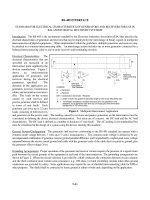
In addition to power and energy, the shape of the pulse is also an impor-
tant parameter since the input requirements of the load often require certain
pulse shapes to operate properly. The parameters that determine the shape
of the pulse are depicted in Fig. 1.1. Typically, the overall duration of high
power pulses lies between a few nanoseconds to a few tens of microseconds.
The rise time of the pulse from a pulsed power system, which is defined
to be the time it takes the voltage to rise from 10 to 90% of its peak
value typically ranges from a few nanoseconds to a few microseconds. The
fall time is similarly defined and typically ranges from a few nanoseconds
November 9, 2010 6:13 9in x 6in Explosive Pulsed Power b1031-ch01
Introduction 5
0.0
0.5
1.0
Time
Amplitude, Relative Units
FWHM
Plateau
Rise Time Fall TimePulse Width
Fig. 1.1 Pulse shape parameters.
to a few microseconds. The pulse length or duration is often taken to be
the Full Width of the pulse at Half its Maximum amplitude (Full Width
Half Max, FWHM) or, in some cases, the width of the pulse at 90% of its
peak amplitude. The flatness of the plateau of the pulse is usually another
important parameter when driving certain types of loads, such as high
power microwave tubes like virtual cathode oscillators (VIRCATORs) or
magnetically insulated line oscillators (MILOs).
The particular pulse characteristics required to optimally power a given
load will dictate which type of pulsed power is best suited to drive that load
and what power conditioning is needed. In a low-energy example, if high
peak voltage is required, the explosive driven ferroelectric generator would
be the best choice as the power supply. If high peak current is required, then
the explosive driven ferromagnetic generator would be the better choice
here.
1.3 Explosive Power Sources
There are five basic types of explosive pulsed power systems. Of these, the
one that is the most developed and that generates the highest electrical pow-
ers (kilowatts to gigawatts) and currents (kiloamperes to megaamperes) is
the magnetic flux compression generator (FCG) [9]. These generators were
first developed in the early 1950s. Likewise, the other types of explosive
generators have also been investigated since the 1950s, but they have not