Visible light photocatalysis in organic chemistry
Bạn đang xem bản rút gọn của tài liệu. Xem và tải ngay bản đầy đủ của tài liệu tại đây (16.84 MB, 445 trang )
www.pdfgrip.com
Visible Light Photocatalysis in
Organic Chemistry
www.pdfgrip.com
Visible Light Photocatalysis in
Organic Chemistry
Edited by Corey R. J. Stephenson, Tehshik P. Yoon,
and David W. C. MacMillan
www.pdfgrip.com
Editors
Prof. Corey R. J. Stephenson
University of Michigan
Department of Chemistry
930 N University Avenue
Ann Arbor
MI 48109
USA
All books published by Wiley-VCH are
carefully produced. Nevertheless, authors,
editors, and publisher do not warrant the
information contained in these books,
including this book, to be free of errors.
Readers are advised to keep in mind that
statements, data, illustrations, procedural
details or other items may inadvertently
be inaccurate.
Library of Congress Card No.: applied for
Prof. Tehshik P. Yoon
University of Wisconsin-Madison
Department of Chemistry
1101 University Avenue
Madison
WI 53706
USA
Prof. David W. C. MacMillan
Princeton University
Merck Center for Catalysis at Princeton
NJ 08544
USA
British Library Cataloguing-in-Publication
Data
A catalogue record for this book is
available from the British Library.
Bibliographic information published by
the Deutsche Nationalbibliothek
The Deutsche Nationalbibliothek
lists this publication in the Deutsche
Nationalbibliografie; detailed
bibliographic data are available on the
Internet at <>.
© 2018 Wiley-VCH Verlag GmbH & Co.
KGaA, Boschstr. 12, 69469 Weinheim,
Germany
All rights reserved (including those of
translation into other languages). No part
of this book may be reproduced in any
form – by photoprinting, microfilm, or
any other means – nor transmitted or
translated into a machine language
without written permission from the
publishers. Registered names, trademarks,
etc. used in this book, even when not
specifically marked as such, are not to be
considered unprotected by law.
Print ISBN: 978-3-527-33560-2
ePDF ISBN: 978-3-527-67417-6
ePub ISBN: 978-3-527-67416-9
Mobi ISBN: 978-3-527-67415-2
oBook ISBN: 978-3-527-67414-5
Cover Design Adam-Design, Weinheim,
Germany
Typesetting SPi Global, Chennai, India
Printing and Binding
Printed on acid-free paper
www.pdfgrip.com
v
Contents
1
An Overview of the Physical and Photophysical Properties of
[Ru(bpy)3 ]2+ 1
Daniela M. Arias-Rotondo and James K. McCusker
1.1
1.2
1.2.1
1.2.2
1.3
1.3.1
1.3.2
1.4
1.5
1.6
1.7
Introduction 1
[Ru(bpy)3 ]2+ : Optical and Electrochemical Properties 4
Optical Properties 4
Electrochemical Properties 6
Excited State Kinetics 8
Steady-State Emission 8
Time-Resolved Emission 10
Excited-State Reactivity of [Ru(bpy)3 ]2+ 11
Energy Transfer: Förster and Dexter Mechanisms 12
Electron Transfer 14
Probing the Mechanism, Stage I: Stern–Volmer Quenching
Studies 14
Probing the Mechanism, Stage II: Electron Versus Energy
Transfer 16
Designing Photocatalysts: [Ru(bpy)3 ]2+ as a Starting Point 20
Conclusion 22
References 23
1.8
1.9
1.10
2
Visible-Light-Mediated Free Radical Synthesis 25
Louis Fensterbank, Jean-Philippe Goddard, and Cyril Ollivier
2.1
2.2
2.3
2.3.1
2.3.1.1
2.3.1.2
2.3.1.3
2.3.2
Introduction 25
Basics of the Photocatalytic Cycle 26
Generation of Radicals 27
Formation of C-Centered Radicals 27
Dehalogenation (I, Br, Cl) 27
Other C-Heteroatom Cleavage 29
C—C Bond Cleavage 29
Formation of N-Centered Radicals 30
www.pdfgrip.com
vi
Contents
2.4
2.4.1
2.4.2
2.4.3
2.4.4
2.4.5
2.4.6
2.5
2.5.1
2.5.2
2.5.2.1
2.5.2.2
2.5.2.3
2.5.3
2.5.3.1
2.5.3.2
2.5.3.3
2.6
2.6.1
2.6.2
2.6.3
C—X Bond Formation 30
C—O Bond 30
C—N Bond 32
C—S and C—Se Bonds 33
C—Br Bond 34
C—F Bond 34
C—B Bond 35
C—C Bond Formation 35
Formation and Reactivity of Aryl Radicals 35
Formation and Reactivity of Trifluoromethyl and Related
Radicals 40
Photocatalyzed Reduction of Perfluorohalogen Derivatives 40
Photocatalyzed Reduction of Perfluoroalkyl-Substituted
Onium Salts 42
Photocatalyzed Formation of Perfluoroalkyl Radicals from
Sulfonyl and Sulfinyl Derivatives 43
Formation and Reactivity of Alkyl and Related Radicals 45
C—C Bond Formation Through Photocatalyzed Reduction
of Halogen Derivatives and Analogs 45
C—C Bond Formation Through Photocatalyzed Oxidation of
Electron-Rich Functional Group 47
C—C Bond Formation Through Photocatalyzed Oxidation
of Amino Group 48
Radical Cascade Applications 49
Intramolecular Polycyclization Processes 49
Sequential Inter- and Intramolecular Processes 51
Sequential Radical and Polar Processes 56
References 59
3
Atom Transfer Radical Addition using Photoredox
Catalysis 73
Theresa M. Williams and Corey R. J. Stephenson
3.1
3.2
3.2.1
3.2.1.1
3.2.1.2
3.2.2
3.2.2.1
3.3
3.3.1
3.4
3.5
3.6
3.7
Introduction 73
Transition Metal-Catalyzed ATRA 77
Ruthenium- and Iridium-Based ATRA 77
Mechanistic Investigations 77
Ruthenium- and Iridium-Based ATRA 80
Copper-Mediated ATRA 81
Trifluoromethylation 82
Other Photocatalysts for ATRA Transformations 84
p-Anisaldehyde 84
Semiconductor 86
Atom Transfer Radical Cyclization (ATRC) 87
Atom Transfer Radical Polymerization (ATRP) 89
Conclusion 90
References 90
www.pdfgrip.com
Contents
4
Visible Light Mediated 𝛂-Amino C—H Functionalization
Reactions 93
You-Quan Zou and Wen-Jing Xiao
4.1
4.2
Introduction 93
Visible Light Mediated α-Amino C—H Functionalization Via
Iminium Ions 95
Aza-Henry Reaction 95
Mannich Reaction 100
Strecker Reaction 104
Friedel–Crafts Reaction 105
Alkynylation Reaction 108
Phosphonation Reaction 109
Addition of 1,3-Dicarbonyls 109
Formation of C—N and C—O Bonds 110
Miscellaneous 112
Visible Light Mediated α-Amino C—H Functionalization Via
α-Amino Radicals 116
Addition to Electron-Deficient Aromatics 116
Addition to Electron-Deficient Alkenes 116
Miscellaneous 120
Conclusions and Perspectives 121
References 122
4.2.1
4.2.2
4.2.3
4.2.4
4.2.5
4.2.6
4.2.7
4.2.8
4.2.9
4.3
4.3.1
4.3.2
4.3.3
4.4
5
Visible Light Mediated Cycloaddition Reactions 129
Scott Morris, Theresa Nguyen, and Nan Zheng
5.1
5.2
5.2.1
5.2.2
5.2.3
5.2.4
5.2.5
5.3
5.3.1
5.3.2
5.3.3
5.3.4
5.3.5
5.3.6
5.4
5.4.1
5.4.2
5.4.3
5.4.4
5.5
Introduction 129
[2+2] Cycloadditions: Formation of Four-Membered Rings 130
Introduction to [2+2] Cycloadditions 130
Utilization of the Reductive Quenching Cycle 130
Utilization of the Oxidative Quenching Cycle 135
Utilization of Energy Transfer 139
[2+2] Conclusion 142
[3+2] Cycloadditions: Formation of Five-Membered Rings 143
Introduction to [3+2] Cycloadditions 143
[3+2] Cycloaddition of Cyclopropylamines 143
1,3-Dipolar Cycloaddition of Azomethine Ylides 145
[3+2] Cycloaddition of Aryl Cyclopropyl Ketones 146
[3+2] Cycloaddition via ATRA/ATRC 146
[3+2] Conclusion 148
[4+2] Cycloadditions: Formation of Six-Membered Rings 149
Introduction to [4+2] Cycloadditions 149
[4+2] Cycloadditions Using Radical Anions 149
[4+2] Cycloadditions Using Radical Cations 151
[4+2] Conclusion 154
Conclusion 155
References 156
vii
www.pdfgrip.com
viii
Contents
6
Metal-Free Photo(redox) Catalysis 159
Kirsten Zeitler
6.1
6.1.1
6.1.2
6.2
6.2.1
6.2.2
6.2.2.1
6.2.2.2
6.2.2.3
Introduction 159
Background 162
Classes of Organic Photocatalysts 162
Applications of Organic Photocatalysts 166
Energy Transfer Reactions 166
Reductive Quenching of the Catalyst 171
Cyanoarenes 171
Quinones 172
Cationic Dyes: Pyrylium, Quinolinium, and Acridinium
Scaffolds 173
Xanthene Dyes and Further Aromatic Scaffolds 188
Oxidative Quenching of the Catalyst 203
New Developments 214
Upconversion 215
Consecutive Photoelectron Transfer 215
Multicatalysis 216
Conclusion and Outlook 224
References 224
6.2.2.4
6.2.3
6.2.4
6.2.4.1
6.2.4.2
6.2.4.3
6.3
7
Visible Light and Copper Complexes: A Promising Match in
Photoredox Catalysis 233
Suva Paria and Oliver Reiser
7.1
7.2
7.3
Introduction 233
Photophysical Properties of Copper Catalysts 234
Application of Copper Based Photocatalysts in Organic
Synthesis 237
Outlook 247
Acknowledgment 248
References 248
7.4
8
Arene Functionalization by Visible Light Photoredox
Catalysis 253
Durga Hari Prasad, Thea Hering, and Burkhard König
8.1
8.1.1
8.1.2
8.1.3
8.1.4
8.2
8.3
8.4
Introduction 253
Aryl Diazonium Salts 253
Diaryl Iodonium Salts 268
Triaryl Sulfonium Salts 272
Aryl Sulfonyl Chlorides 273
Applications of Aryl Diazonium Salts 274
Photoinduced Ullmann C—N Coupling 276
Conclusion 278
References 278
www.pdfgrip.com
Contents
9
Visible-Light Photocatalysis in the Synthesis of Natural
Products 283
Gregory L. Lackner, Kyle W. Quasdorf, and Larry E. Overman
References 295
10
Dual Photoredox Catalysis: The Merger of Photoredox Catalysis
with Other Catalytic Activation Modes 299
Christopher K. Prier and David W. C. MacMillan
10.1
10.2
10.3
10.3.1
10.3.2
10.4
Introduction 299
Merger of Photoredox Catalysis with Organocatalysis 300
Merger of Photoredox Catalysis with Acid Catalysis 314
Photoredox Catalysis and Brønsted Acid Catalysis 314
Photoredox Catalysis and Lewis Acid Catalysis 318
Merger of Photoredox Catalysis with Transition Metal
Catalysis 320
Conclusions 328
References 328
10.5
11
Enantioselective Photocatalysis 335
Susannah C. Coote and Thorsten Bach
11.1
11.2
11.3
11.3.1
11.3.2
11.3.3
11.4
Introduction 335
The Twentieth Century: Pioneering Work 336
The Twenty-First Century: Contemporary Developments 341
Large-Molecule Chiral Hosts 341
Small-Molecule Chiral Photosensitizers 343
Lewis Acid-Mediated Photoreactions 353
Conclusions and Outlook 357
References 358
12
Photomediated Controlled Polymerizations 363
Nicolas J. Treat, Brett P. Fors, and Craig J. Hawker
12.1
12.1.1
Catalyst Activation by Light 365
Cu-Catalyzed Photoregulated Atom Transfer Radical
Polymerizations (photoATRP) 365
Photomediated ATRP with Non-Copper-Based Catalyst
Systems 368
Iodine-Mediated Photopolymerizations 371
Metal-Free Photomediated Ring-Opening Metathesis
Polymerization 375
Photoregulated Reversible-Addition Fragmentation Chain
Transfer Polymerizations (photoRAFT) 376
Chain-End Activation by Light 383
Conclusions 384
References 385
12.1.2
12.1.3
12.1.4
12.1.5
12.2
12.3
ix
www.pdfgrip.com
x
Contents
13
Accelerating Visible-Light Photoredox Catalysis in
Continuous-Flow Reactors 389
Natan J. W. Straathof and Timothy Noël
13.1
13.2
13.3
13.4
13.5
Introduction 389
Homogeneous Photocatalysis in Single-Phase Flow 392
Gas–liquid Photocatalysis in Flow 401
Heterogeneous Photocatalysis in Flow 408
Conclusions 410
Conflict of Interest 410
References 410
14
The Application of Visible-Light-Mediated Reactions to the
Synthesis of Pharmaceutical Compounds 415
James. J. Douglas
14.1
14.2
14.3
14.4
14.5
14.6
14.7
14.8
14.9
Introduction 415
Asymmetric Benzylation 415
Amide Bond Formation 416
C—H Azidation 417
Visible-Light-Mediated Benzothiophene Synthesis 418
α-Amino Radical Functionalization 419
Visible-Light-Mediated Radical Smiles Rearrangement 422
Photoredox and Nickel Dual Catalysis 423
The Scale-Up of Visible-Light-Mediated Reactions Via Continuous
Processing 426
References 428
Index 431
www.pdfgrip.com
1
1
An Overview of the Physical and Photophysical Properties
of [Ru(bpy)3 ]2+
Daniela M. Arias-Rotondo and James K. McCusker
Michigan State University, Department of Chemistry, 578 S Shaw Lane, East Lansing, MI 48824, United States
1.1 Introduction
The photophysics and photochemistry of transition-metal coordination compounds have been studied for over half a century [1, 2]. In particular, metal
polypyridyl complexes – especially those that possess visible charge transfer
absorptions – have played a central role in efforts to understand fundamental
aspects of excited-state electronic structure and dynamics, as well as efforts
to develop a wide range of solar energy conversion strategies [3, 4]. Their
footprint in the area of synthetic organic chemistry was largely nonexistent
until 2008 [5], when MacMillan and coworkers [6] reported the first example of
a transition-metal-based charge transfer compound, [Ru(bpy)3 ]2+ (where bpy
is 2,2′ -bipyridine), acting as a photocatalyst (PC) in an asymmetric alkylation
of aldehydes; simultaneously, Yoon and coworkers [7] reported [2+2] enone
cycloadditions photocatalyzed by [Ru(bpy)3 ]2+ . Following those initial reports,
several groups have explored the use of coordination compounds as photocatalysts for a variety of organic transformations [8]. These compounds engage
in single-electron transfer (SET) processes with organic substrates, generating
organic radicals, which play a major role in organic synthesis. This new kind of
catalysis has opened the door to synthetically useful reactions that could not be
performed otherwise.
The majority of the photocatalysts used nowadays are polypyridyl complexes of
either Ru(II) or Ir(III) [8]. The large number of examples using [Ru(bpy)3 ]2+ might
make this compound look like a “one size fits all” photocatalyst, when in reality,
the best photocatalyst for a reaction is determined by the kinetics and thermodynamics of the system of interest. The purpose of this chapter is to provide
the necessary tools to understand the different factors that come into play when
choosing a photocatalyst. To this end, we will use [Ru(bpy)3 ]2+ as an example; it is
important to note that the concepts we will discuss apply to most transition-metal
polypyridyl compounds.
* An expanded discussion of these topics can be found in Chem. Soc. Rev. 2016, 45, 5803–5820.
Visible Light Photocatalysis in Organic Chemistry, First Edition.
Edited by Corey R. J. Stephenson, Tehshik P. Yoon and David W. C. MacMillan.
© 2018 Wiley-VCH Verlag GmbH & Co. KGaA. Published 2018 by Wiley-VCH Verlag GmbH & Co. KGaA.
www.pdfgrip.com
2
1 An Overview of the Physical and Photophysical Properties of [Ru(bpy)3 ]2+
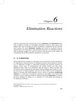
Scheme 1.1 shows two examples of catalytic cycles using Ru(II)-based photoredox catalysts: in both cases, the first step is the absorption of a photon by
the photocatalyst to generate an excited state that then engages in redox reactions. The first cycle in Scheme 1.1, reported by Zheng and coworkers [9], is called
reductive, because the excited photocatalyst is reduced. The second one, reported
by Cano-Yelo and Deronzier [10], is an oxidative cycle; the photocatalyst is first
oxidized and then reduced to reform its resting state.
As shown in Scheme 1.1, most steps in a catalytic cycle are bimolecular reactions. In a very general way, for any catalytic cycle involving [Ru(bpy)3 ]2+ , we can
write the series of reactions in Scheme 1.2 [11, 12]. The first step is the absorption
of a visible light photon by the photocatalyst in its ground state and its consequent promotion to an electronic excited state (PC*); the backward reaction is
the ground-state recovery (this process can be radiative (i.e., emission) and/or
nonradiative, as will be discussed in Section 1.3). For the excited photocatalyst to
react with a molecule (R), both species must diffuse toward each other, forming
a “precursor complex.” Then, the reaction takes place; of the many kinds of reactions that could happen, only electron and energy transfer are relevant for our
discussion. After the reaction, the products must diffuse away from each other; if
they cannot escape the solvent cage fast enough, a back reaction may take place.
This relatively simple scheme allows us to outline the main points that need to
be considered when choosing a photocatalyst:
1) Photocatalytic reactions make use of the enhanced reactivity of the photocatalyst in its excited state; for this reason, a photocatalyst must possess a good
absorption cross section, preferably over a broad range of wavelengths that
the other species in the reaction mixture do not absorb.1
2) The quantum yield of formation of the reactive excited state should be as high
as possible (preferably, near unity); that state must persist long enough to
undergo the desired reaction with the substrate, and then cleanly regenerate
in order to maintain its viability as part of a catalytic cycle. In the context of
Scheme 1.2, these latter criteria mean that k d and k q must be larger than k 0 ,
so that the PC* can diffuse toward the appropriate molecule and react with it
before going back to the ground state [13].
3) If the catalytic cycle involves electron transfer, the excited- and ground-state
redox potentials of the photocatalyst must provide for an exothermic (or
at worst weakly endothermic) reaction; reversible electrochemistry is also
desirable as an indicator of the stability of the photocatalyst over multiple
turnovers.2
4) Synthetic accessibility and, more importantly, tunability are critical in order
to tailor the excited-state reactivity of the photocatalyst to the reaction of
interest.
1 Strictly speaking, it is only necessary for the photocatalyst to absorb light of one wavelength that
the other species present in the reaction mixture do not absorb; having the photocatalyst absorb
over a wider range of wavelengths makes it more versatile.
2 This is not necessary in the case of an energy-transfer photocatalyst, but those are far less
common (see Prier, C. K.; Rankic, D. A.; MacMillan, D. W. op. cit. and references therein).
www.pdfgrip.com
CO2H
+•
N
H
N
H
+
•
N
H
–
BF4
N2+
[Ru(bpz)3]2+*
Visible
light
Visible
light
CO2H
CO2H
Ph
[Ru(bpz)3]+
[Ru(bpy)3]2+*
[Ru(bpy)3]
+
2+
H
[Ru(bpz)3]2+
Ph
Ph
Ph
•
[Ru(bpy)3]3+
•
+•
N
H
N
H
CO2H
CO2H
N
N2
•
H
Scheme 1.1 Examples of reductive catalytic cycle (left; see also [9]) and oxidative catalytic cycle (right; see also [10]) involving Ru(II)-based photoredox
catalysts; bpz is 2,2’-bipyrazine.
www.pdfgrip.com
4
1 An Overview of the Physical and Photophysical Properties of [Ru(bpy)3 ]2+
kd
hν
PC
PC*
R
PC*
R
k0
R
k−d
k−q
kq
kesc
PC
R*
PC
R*
k-esc
Scheme 1.2 Simplified kinetic scheme for a general quenching process (see also [11, 12]).
Given the various criteria just enumerated, it is no surprise that polypyridyl
complexes of Ru(II) and Ir(III) have proved useful as photoredox catalysts. These
compounds strongly absorb visible light, which makes it easy to selectively excite
them relative to the organic substrates for typical reactions of interest. Their
excited states are formed with ∼100% efficiency [14] and their lifetimes range
from 300 ns to 6 μs, which is long enough for them to engage in bimolecular
reactions [3, 15]. As a class, these compounds are generally stable with respect
to decomposition (both photochemical and thermal) and typically exhibit
reversible redox behavior. They are also emissive, which facilitates mechanistic
studies (as discussed in Sections 1.7 and 1.8); however, it is not a requirement.
The synthesis of transition-metal polypyridyl complexes has been studied
in great detail [4, 16], as well as the effect that different ligands have on the
properties of the ground and excited states [17]. All these properties make these
compounds the preferred choice for photocatalysts.
As mentioned above, we will discuss the properties of the ground and excited
states of [Ru(bpy)3 ]2+ , as a prototype for photoredox catalysis, describing
the necessary experiments to fully understand their properties. Using this as
a foundation, we will then focus on the processes that take place during a
photocatalytic cycle and the experiments that allow for discriminating between
various mechanistic possibilities (the main question being energy transfer versus
reductive/oxidative electron transfer). In so doing, our goal is to provide a basic
blueprint for how to identify, characterize, and ultimately design photocatalysts
for use in a wide variety of chemical transformations.
1.2 [Ru(bpy)3 ]2+ : Optical and Electrochemical
Properties
1.2.1
Optical Properties
The electronic absorption spectrum of [Ru(bpy)3 ](PF6 )2 in acetonitrile is shown
in Figure 1.1. The intense absorption at 285 nm corresponds to a ligand-centered
transition (πL → πL *), which has been assigned by comparison with the absorption spectrum of the protonated ligand [18]. The band in the visible region
www.pdfgrip.com
1.2 [Ru(bpy)3 ]2+ : Optical and Electrochemical Properties
Energy (cm–1)
25 000
20 000
Molar absorptivity (104 M–1 cm–1)
Molar absorptivity (104 M–1 cm–1)
30 000
6
4
18 000
1.0
0.5
0.0
350
400
450
500
550
Wavelength (nm)
2
0
300
400
Wavelength (nm)
500
600
Figure 1.1 Electronic absorption spectrum of [Ru(bpy)3 ](PF6 )2 in acetonitrile at room
temperature. The inset shows the metal-to-ligand charge transfer (MLCT) band.
(𝜆max = 452 nm) corresponds to a metal-to-ligand charge transfer (MLCT)
transition. As the name implies, this type of excited state can be viewed as
the promotion of an electron from a metal-based orbital to a ligand-based
one. Because of this spatial redistribution of electron density, this transition is
responsible for the enhanced redox activity of the excited state relative to what
is observed in the ground state, and makes the compound an efficient photocatalyst. Charge transfer transitions are typically very intense, with extinction
coefficients in the range of 103 to 104 M−1 cm−1 [19] (in acetonitrile at room
temperature, 𝜀 ∼ 15 000 M−1 cm−1 for [Ru(bpy)3 ]2+ ).
Two additional features can be seen in the absorption spectrum of [Ru(bpy)3 ]2+ .
The origin(s) of the weaker features at 330 and 350 nm are less clear-cut and
have been the subject of considerable debate over the years. They are most
likely due to ligand–field (so-called “d–d”) transitions within the d-orbital
manifold of the metal. The inferred intensity belies this assignment to a certain
extent (the symmetry-forbidden nature of d–d bands typically limits their
absorptivities to the range of 10–100 M−1 cm−1 ) [19] but the proximity of both
the ligand-centered and MLCT features influences these values in the present
case. These metal-centered transitions put electronic density in orbitals that
are antibonding with respect to the metal–ligand bonds and are therefore
responsible for ligand loss reactions [3]. These three types of transitions are
schematized in the simplified molecular orbital diagram in Scheme 1.3.
It is worth noting that most organic substrates, with the exception of highly
conjugated systems, do not absorb visible light (cf. ligand-based transition in
Figure 1.1). Thus, the use of visible light allows the selective excitation of the
photocatalyst and not the organic reactants, which prevents the uncontrolled
formation of organic radicals that could lead to unwanted side reactions.
5
www.pdfgrip.com
1 An Overview of the Physical and Photophysical Properties of [Ru(bpy)3 ]2+
dσ*M
π*L
MLCT
IL
LF
6
dπM
dσM
Unoccupied π*L
dπM
πL
Occupied σL
(lone pairs)
σL
Occupied πL
ML6
Metal
Ligands
Scheme 1.3 Simplified molecular orbital diagram for an octahedral compound with
π-acceptor ligands. The three types of electronic transitions discussed in the text are indicated
by the arrows.
2+*
2+
N
N
N
RuII
N
N
hν
N
N
N
Oxidant
RuIII
N
N
N
N
Reductant
Scheme 1.4 A qualitative representation of a metal-to-ligand charge transfer state in
[Ru(bpy)3 ]2+ . The spatial separation of charge within the molecule following light absorption is
critical for the redox activity of the excited state.
A metal-to-ligand charge transfer transition can be thought of as the simultaneous oxidation of the metal center and reduction of the ligand [20] that yields
[RuIII (bpy∙− )(bpy)2 ]2+* (see Scheme 1.4). Unlike ligand- or metal-based electronic
transitions (where the electron stays in the same spatial region before and after
excitation), the MLCT results in the separation of charges within the compound,
which confers a special reactivity to the resulting state: the oxidized metal (RuIII )
can act as an oxidant, gaining an electron to form RuII ; likewise, the reduced ligand (bpy∙− ) can donate its extra electron, acting as a reductant. In its excited
state, [Ru(bpy)3 ]2+ is both a stronger oxidant and reductant than in its ground
state. Moreover, both the reductant and oxidant are simultaneously present in the
same molecule, making this class of compounds very versatile for applications in
photocatalysis.
1.2.2
Electrochemical Properties
Most of the examples using transition-metal photocatalysts take advantage
of their ground- and excited-state redox properties. It is thus important to
www.pdfgrip.com
1.2 [Ru(bpy)3 ]2+ : Optical and Electrochemical Properties
Intensity (10 –5 A)
1
0
–1
1
0
–1
–2
Potential (V)
Figure 1.2 Cyclic voltammogram of [Ru(bpy)3 ](PF6 )2 in CH3 CN solution, using 0.1 M
tetrabutylammonium hexafluorophosphate (TBAPF6 ) as supporting electrolyte. Potentials are
referenced to the ferrocene/ferrocenium couple, added as an internal standard.
understand those properties and how they affect the behavior of [Ru(bpy)3 ]2+ as
a photocatalyst. The redox potentials for a coordination compound such
as [Ru(bpy)3 ]2+ can be measured using cyclic voltammetry. The cyclic
voltammogram for [Ru(bpy)3 ](PF6 )2 is shown in Figure 1.2. The oxidation
of the metal center (Eq. (1.1)) is reversible and takes place around 1.00 V
(vs. ferrocene/ferrocenium).
[Ru(bpy)3 ]2+ → [Ru(bpy)3 ]3+ + e−
(1.1)
Three reductions are also observed in the −1.50 to −2.30 V range, all of which
correspond to one-electron reductions of each of the three ligands in succession
(Eqs. (1.2a–1.2c)).
[Ru(bpy)3 ]2+ + e− → [Ru(bpy∙− )(bpy)2 ]+
(1.2a)
[Ru(bpy )(bpy)2 ] + e → [Ru(bpy)(bpy )2 ]
(1.2b)
[Ru(bpy)(bpy∙− )2 ] + e− → [Ru(bpy∙− )3 ]−
(1.2c)
∙−
+
−
∙−
The first two reductions are reversible, whereas the last one (Eq. (1.2c)
is quasi-reversible at best. In terms of photoredox reactions, only the first
reduction (i.e., Eq. (1.2a)) will be relevant for one-electron processes, but the
reversibility of these redox processes is an important consideration when these
compounds are used as photocatalysts, since the compound must be stable
enough in its oxidized or reduced form in order to be viable over the course of
multiple turnovers of a given reaction.
Using the description above, the energy of the MLCT band can be thought of
as the amount of energy necessary to reduce the ligand and oxidize the metal, as
shown in Eq. (1.3).
E(MLCT) ≈ |E(RuIII ∕RuII )| + |E(bpy∕bpy∙− )|
(1.3)
7
www.pdfgrip.com
8
1 An Overview of the Physical and Photophysical Properties of [Ru(bpy)3 ]2+
Several aspects of Eq. (1.3) are worth noting: (i) this is an approximation:
energetics associated with solvation as well as electron correlation effects are not
accounted for in this simplified expression [21]; (ii) the fact that there are two
contributions to the MLCT energy – the oxidation potential of the metal and the
reduction potential of the ligand – implies that the value of E(MLCT) alone is
not sufficient to determine whether a chromphore’s energetics are suitable for a
given reaction. One can observe MLCT bands at roughly the same energy where
one is a very strong reductant but a very weak oxidant (i.e., very negative ligand
reduction potential), or vice-versa. The electrochemical data on the compound
(in addition to other details to be discussed later) is the means by which these
specifics can be deconvolved.
1.3 Excited State Kinetics
We are ultimately interested in bimolecular reactions between an excited
photocatalyst and an organic molecule. Before we can discuss these bimolecular
reactions, however, it is necessary to understand the properties of the excited
state in the absence of a substrate, since the presence (or absence) of a reaction
will ultimately be determined by referring back to the photocatalysts’ intrinsic
excited-state behavior.
1.3.1
Steady-State Emission
Visible light excites [Ru(bpy)3 ]2+ into an 1 MLCT state; this short-lived state
relaxes to an 3 MLCT state within ∼100 fs via intersystem crossing (ISC, with
rate constant k isc ) [22]. The 3 MLCT state can relax back to the ground state
either nonradiatively (with rate constant k nr ) or via phosphorescence (a radiative
pathway; its rate constant is k r ). Equations (1.4)–(1.6) illustrate these processes.
Photoinduced reactions, such as the coordination of a solvent molecule or
ligand loss, can also take place. However, these are not usually observed for
[Ru(bpy)3 ]2+ and related compounds [14], so they will not be discussed here.
h𝜈abs
1
2+∗
[RuII (bpy)3 ]2+ −−−−→ [RuIII (bpy∙− )(bpy)2 ]
kISC
3
−−−→ [RuIII (bpy∙− )(bpy)2 ]
2+∗
kr
[RuIII (bpy∙− )(bpy)2 ]2+∗ −−→ [RuII (bpy)3 ]2+ + h𝜈em
knr
[RuIII (bpy∙− )(bpy)2 ]2+∗ −−−→ [RuII (bpy)3 ]2+ + heat
(1.4)
(1.5)
(1.6)
The solution-phase steady-state emission spectrum of [Ru(bpy)3 ]2+ at room
temperature is shown in Figure 1.3: the emission maximum is at 620 nm. The
same spectrum is obtained regardless of the excitation wavelength, consistent
with the near-unit quantum yield of formation of the emissive 3 MLCT state. The
emission maximum can be used as a first-order approximation of the energy difference between the triplet excited state (3 MLCT) and the ground state (the zero
point energy, E0 ).
www.pdfgrip.com
1.3 Excited State Kinetics
25 000
Energy (cm–1)
20 000 18 000
16 000
14 000
1.0
0.5
0.5
0.0
400
500
600
Wavelength (nm)
700
Normalized emission intensity
Molar absorptivity (104 M–1 cm–1)
1.0
0.0
800
Figure 1.3 Electronic absorption spectrum (black) and steady-state emission spectrum (red)
of [Ru(bpy)3 ](PF6 )2 in acetonitrile at room temperature.
For an emissive substance, the simplest definition of the quantum yield (Φ) of
emission (also called the radiative quantum yield) is the ratio between the number
of photons emitted by a sample and the number of photons absorbed, as shown
in Eq. (1.7).
I
# photons emitted
(1.7)
= em
Φ=
# photons absorbed Iabs
For every photon absorbed, one molecule is promoted to the excited state. The
radiative quantum yield can also be described in terms of a kinetic competition,
specifically the relative rate(s) of processes giving rise to emission versus the rates
of all processes that serve to deplete the population of that emissive state. Referring to Eqs. (1.5) and (1.6), for [Ru(bpy)3 ]2+ in the absence of any other species,
Φ can be expressed as
Φ0 =
kr
k
= r
kr + knr
k0
(1.8)
Radiative quantum yields can be measured as absolute values (i.e., Eq. (1.7)) or
relative to some standard. To measure an absolute quantum yield it is necessary
to detect every photon that is emitted by the sample, which tends to be quite labor
intensive. Although instrumentation has recently become commercially available
to allow for (relatively) facile measurement of absolute radiative quantum yields,3
most of the quantum yields in literature are determined and reported relative to
a standard with a known absolute quantum yield [23]. The choice of the standard
depends on the characteristics of the molecule of interest; it is best if the standard
and the molecule are dissolved in the same solvent and have similar absorption
and emission spectra. [Ru(bpy)3 ]2+ is commonly used as a standard for relative
3 .
9
www.pdfgrip.com
10
1 An Overview of the Physical and Photophysical Properties of [Ru(bpy)3 ]2+
quantum yields of transition-metal complexes. In deoxygenated4 acetonitrile at
room temperature its quantum yield is 0.095 [24]. The relative quantum yield of
a sample can be calculated using Eq. (1.9),
(
)(
)
Ix ∕Ax
𝜂x 2
(1.9)
Φx = Φstd
Istd ∕Astd
𝜂std
where x refers to the molecule of interest and std to the standard; Ix and I std
are the integrated areas of the corrected emission spectra,5 Ax and Astd are the
absorbances at the excitation wavelength, and 𝜂 x and 𝜂 std are the indexes of refraction of the solutions, taken to be equal to those of the neat solvents. For relative
quantum yield determinations, it is crucial for the experimental conditions for
both the sample and the standard to be exactly the same. A more detailed discussion of methodology for measuring and quantifying emission data is beyond
the scope of this chapter, but a number of excellent resources are readily available
[25, 26].
As will be discussed later, observing a change (specifically, an attenuation) in
the quantum yield of emission of a photocatalyst in the presence of a quencher
is an important initial indicator that a reaction is occurring between the excited
state of the photocatalyst and one or more substrate(s).
1.3.2
Time-Resolved Emission
Both the radiative and nonradiative decay processes (Eqs. (1.5) and (1.6)) are of
first order with respect to the excited state (ES) and give rise to the following rate
expression for the loss of the excited state:
d[ES]
(1.10)
= kr [ES] + knr [ES] = (kr + knr )[ES] = k0 [ES]
dt
where k 0 = k nr + k r . Equation (1.10) can be integrated to yield the known rate law
for a first-order reaction, shown in Eq. (1.11).
−
[ES] = [ES]0 e−k0 t
(1.11)
The inverse of the observed rate constant, k0 −1 , is the lifetime (𝜏 0 ) of the
excited state; experimentally, this can be measured with time-resolved emission
or absorption spectroscopy.
In a time-resolved emission experiment, the (emissive) sample is excited at
a wavelength close to its absorption maximum, with the emission collected at
90∘ with respect to the excitation beam in order to minimize scatter. A typical
time-resolved emission trace for [Ru(bpy)3 ]2+ in acetonitrile is shown in
Figure 1.4. By fitting the trace to an exponential decay, 𝜏 0 can be found. For
[Ru(bpy)3 ]2+ , the lifetime ranges from 500 to 1000 ns, depending on a number
of variables including solvent, oxygen concentration in the sample, temperature,
and so on [3].
4 This is necessary because O2 can quench the 3 MLCT excited state of [Ru(bpy)3 ]2+ .
5 Spectra refer to emission spectra that have been properly corrected for the fluorimeter’s
instrument response characteristics. References on emission spectroscopy can be consulted for
further information on this point.
www.pdfgrip.com
1.4 Excited-State Reactivity of [Ru(bpy)3 ]2+
–1
cm )
–1
pump: 475 nm
1.0
4
Molar absorptivity (10 M
1.0
0.5
probe: 620 nm
0.5
0.5
0.0
400
500
600
700
0.0
800
Normalized emission intensity
Normalized emission intensity (620 nm)
1.0
Wavelength (nm)
0.0
0
2
4
Time (μs)
Figure 1.4 Time-resolved emission data (grey line) for [Ru(bpy)3 ]2+ in acetonitrile at room
temperature. The sample was excited at 475 nm and emission was detected at 620 nm (as
shown in the inset). The red trace shows the fit to a single exponential decay with 𝜏 = 930 ns.
Combining the excited-state lifetime and the quantum yield, it is possible to
calculate k r and k nr . Rearranging Eq. (1.8), we obtain Eqs. (1.12) and 1.13).
kr = Φ0 × k0
(1.12)
knr = k0 − (Φ0 × k0 )
(1.13)
It is important to remark that k r is an intrinsic property of the molecule, and
as such, it remains constant no matter what reactions the excited state engages
in. On the other hand, k nr varies when quenching processes (such as energy or
electron transfer) take place. All the information that we will be interested in
for a photocatalytic cycle (in other words, the information about any processes
competing with the emission) is contained in k nr ; in this regard, k r can be viewed
as a probe, providing insight into the dynamics of the system manifesting in k nr .
This concept is discussed in greater detail in Section 1.7.
1.4 Excited-State Reactivity of [Ru(bpy)3 ]2+
In its excited state, [Ru(bpy)3 ]2+ can act as an energy donor, an electron acceptor, or an electron donor; which of these processes dominates is determined by
thermodynamic and kinetic factors associated with a given reaction [27].
The inherent competition that exists among these various reaction pathways is
depicted in Eqs. (1.14a–1.14c); the energy transfer route can furthermore be subdivided according to the specific mechanism of that process. As a result, although
determining whether the excited state of the chromophore is reacting can be as
straightforward as observing emission quenching, mechanistic discrimination as
to the nature of that reaction generally requires considerably more work. The next
11
www.pdfgrip.com
12
1 An Overview of the Physical and Photophysical Properties of [Ru(bpy)3 ]2+
sections will discuss these different processes and describe experiments that are
typically employed in order to distinguish among them.
[RuIII(bpy−)(bpy)2]2+*
+Q
kEnT
[RuII(bpy)3]2+ + Q*
(1.14a)
+A
kox
[RuIII(bpy)3]3+ + A•−
(1.14b)
+D
kred
[RuII(bpy−)(bpy)2]+ + D•+
(1.14c)
1.5 Energy Transfer: Fưrster and Dexter Mechanisms
Energy transfer is a process by which excess energy contained in one molecule
(the donor) is transferred to another molecule (the acceptor). In the context of
the chemical systems being discussed herein, that excess energy comes from the
absorption of a photon by the donor to create an electronic excited state. The
product of the reaction is an electronically excited acceptor molecule concomitant with reformation of the electronic ground state of the donor, as shown in
Eq. (1.15).
kEnT
D∗ + A −−−→ D + A∗
(1.15)
Although energy transfer can occur as the result of emission from the donor
and subsequent absorption of that emitted light by the acceptor (the so-called
“trivial” mechanism), energy transfer more typically occurs via nonradiative
processes (i.e., the emission and reabsorption of light do not occur). The two
most common mechanisms of nonradiative energy transfer are known as Förster
(through-space) and Dexter (through-bond or “exchange”) energy transfer.
These mechanisms are depicted in Scheme 1.5. It should be noted that both
Förster and Dexter transfers yield the same products (i.e., ground-state donor
and excited-state acceptor), although the physical origins of the reaction are
fundamentally different [28].
Förster energy transfer [29] is a dipolar mechanism that takes place through
space: the transition moment dipole of the donor couples nonradiatively with the
transition moment dipole of the acceptor. Because of the dipolar nature of this
mechanism, no orbital overlap is necessary between the donor and the acceptor.
This makes Förster energy transfer operational at long distances that can range
from 1 to 10 nm [30]. In the photosynthetic apparatus, the energy absorbed by the
antenna complex is shuttled to the reaction center via Förster energy transfer [31].
An overlap between the emission spectrum of the donor and the electronic
absorption spectrum of the acceptor is necessary for the energy transfer to occur:
for this reason, Förster transfer is often referred to as fluorescence resonance
energy transfer, or FRET. A schematic representation of this resonance condition (which in reality is simply a reflection of energy conservation for the energy
transfer process) is shown in Scheme 1.6. The organic reactants usually involved
www.pdfgrip.com
1.5 Energy Transfer: Förster and Dexter Mechanisms
Förster energy transfer
hν
D
D*
A
D*
A
D
A*
A
D
A*
A
D*
Dexter energy transfer
Scheme 1.5 Förster and Dexter energy transfer mechanisms.
Donor
Acceptor
Emission intensity
Molar absorptivity
Energy (cm−1)
Scheme 1.6 Schematic emission spectrum of the donor and absorption spectrum of the
acceptor. The shaded region is the spectral overlap.
in photocatalyzed reactions do not readily absorb light in the visible region of
the spectrum, so the spectral overlap between their absorption spectrum and
the emission spectrum of [Ru(bpy)3 ]2+ is usually negligible. As a consequence,
Förster energy transfer is not a common reaction pathway for the systems that
are discussed in this chapter.
The Dexter mechanism [32, 33], on the other hand, is best thought of as
two concomitant electron transfer reactions (see Scheme 1.5). Except in rare
cases, electron transfer is a through-bond process, meaning that Dexter transfer
requires orbital overlap between the donor and the acceptor in order for the
energy transfer process to proceed: this limits its occurrence to shorter distances
than the Förster mechanism (typically no more than 10 Å). In other words, for a
bimolecular reaction the Dexter process requires physical contact between the
excited donor and the acceptor. On the plus side, since it is an exchange process
(as opposed to a resonance one), no spectral overlap is required.
Molecular oxygen can quench the excited state of many transition-metal
polypyridyl compounds via Dexter energy transfer [34, 35]. For this reason, most
photophysical measurements involving [Ru(bpy)3 ]2+ and other transition-metal
complexes must be carried out in deoxygenated solutions.
13
www.pdfgrip.com
14
1 An Overview of the Physical and Photophysical Properties of [Ru(bpy)3 ]2+
1.6 Electron Transfer
A generic electron transfer process is represented in Eq. (1.16). In a simple electron transfer reaction (the kind that we are interested in), no bonds are formed
or broken; this is known as an outer sphere electron transfer.
keT
D + A −−−→ D+ + A−
(1.16)
The kinetics of outer sphere electron transfer can be described using Marcus
theory [36]. In bimolecular systems (such as the ones of interest in organic synthesis), the distance between the donor and the acceptor (as well as their relative
orientations) can vary, affecting the rate of electron transfer. For simplicity, we
will consider the donor and the acceptor to be at a fixed distance and orientation.
Under those conditions, the rate constant for outer sphere electron transfer can
be written as shown in Eq. (1.17),
[
]
(−ΔG∘ + 𝜆)2
2π
1
2
exp
|H | √
(1.17)
keT =
ℏ AB
4𝜆kB T
4π𝜆kB T
where ΔG∘ is the driving force for electron transfer (which depends on the redox
potentials of the donor and the acceptor), H AB represents the electronic coupling between the donor and the acceptor, and 𝜆 is the reorganization energy.
This latter term reflects energetics associated with the structural changes in going
from reactants to products as well as the reorganization of the solvent molecules
around them. The magnitude of the electronic coupling (H AB ) depends on the
distance and orientation of the donor and the acceptor and therefore tends to be
difficult to specify for bimolecular reactions in solution.
Even though electron transfer and Dexter energy transfer are closely related,
two important differences should be noted. First, because two electrons are
exchanged instead of one, Dexter energy transfer has a stronger distance
dependence than electron transfer (typically e−2r as opposed to e−r for electron
transfer) [33]. Second, since electron transfer leads to a new charge distribution,
the reorganization energy (especially the solvent contribution) is much larger
than that associated with Dexter energy transfer [37].
The product of a Dexter energy transfer differs from that of an electron transfer
because no charge-separated species is formed. This turns out to be an extremely
important distinction that helps differentiate these two reaction pathways, as will
be discussed later.
1.7 Probing the Mechanism, Stage I: Stern–Volmer
Quenching Studies
The simplest experiment that can be performed is a Stern–Volmer quenching
study. With this experiment, it is possible to determine whether a bimolecular
reaction is taking place. While this is extremely useful information, it is important to stress that this experiment does not provide any mechanistic information
by itself. As will become apparent in the discussion to follow, both energy and
www.pdfgrip.com
1.7 Probing the Mechanism, Stage I: Stern–Volmer Quenching Studies
electron transfer reactions involving the excited state of the chromophore will
yield experimentally indistinguishable results from a Stern–Volmer quenching
study. It is only through the application of additional experiments (most notably
time-resolved absorption spectroscopy) that further insight into the nature of the
reaction responsible for the quenching can be gleaned.
In Section 1.3, the radiative and nonradiative pathways for the excited state
were described. When a species other than [Ru(bpy)3 ]2+ is present in solution,
the possibility of one or more additional reactions, such as electron and/or energy
transfer, is introduced. When this happens, the excited state is quenched (the
ground state is recovered). In a very general way, when a quencher is present, we
can write the reaction shown in Eq. (1.18).
kr
[RuII(bpy)3]2+
hν
[RuIII(bpy−)(bpy)2]2+*
knr
+Q
kq
products
(1.18)
In this scheme, the rate at which the excited state disappears is given by Eq.
(1.19).
d[ES]
(1.19)
= k0 [ES] + kq [ES][Q]
−
dt
For bimolecular quenching to take place, k q [Q] must be larger than k 0. This
condition is usually met if the excited-state lifetime is on the nanosecond to
microsecond time scale. Otherwise, the excited state relaxes back to the ground
state before it can diffuse to and react with the substrate (Q) [20]. The goal of
Stern–Volmer studies is to determine whether the excited state reacts with the
quencher. Quantifying k q is most easily done by carrying out the study under
pseudo first-order conditions: the concentration of the quencher must be at least
two orders of magnitude larger than that of the photocatalyst,6 so that [Q] can
be assumed to be constant throughout the experiment. This collapses Eq. (1.19)
to Eq. (1.20) and allows for the determination of k q (Eq. (1.21)). The observed
rate constant (k obs ) varies with the concentration of the quencher.
−
d[ES]
= (k0 + kq [Q])[ES] = kobs [ES]
dt
kobs = (k0 + kq [Q])
(1.20)
(1.21)
k obs may be directly determined using time-resolved spectroscopy. If the sensitizer is emissive, this is most easily done via time-resolved emission spectroscopy:
by measuring the decay rate constant at several quencher concentrations, the
quenching constant k q can be found when fitting the results to Eq. (1.22).
k0 + kq [Q]
kq [Q]
kobs
=
=1+
k0
k0
k0
(1.22)
6 Strictly, it must be [Q] ≫ [ES], but since evaluating the concentration of the excited state is not
trivial, it is simpler to make [Q] ≫ [photocatalyst].
15