Tài liệu AMD Thermal, Mechanical, and Chassis Cooling Design Guide docx
Bạn đang xem bản rút gọn của tài liệu. Xem và tải ngay bản đầy đủ của tài liệu tại đây (689.33 KB, 30 trang )
Publication # 23794 Rev: H
Issue Date: November 2002
AMD
Thermal, Mechanical,
and Chassis Cooling
Design Guide
Trademarks
AMD, the AMD Arrow logo, AMD Athlon, AMD Duron, and combinations thereof are trademarks of
Advanced Micro Devices, Inc.
Other product names used in this publication are for identification purposes only and may be trademarks of their
respective companies.
© 2000–2002 Advanced Micro Devices, Inc. All rights reserved.
The contents of this document are provided in connection with Advanced
Micro Devices, Inc. (“AMD”) products. AMD makes no representations or
warranties with respect to the accuracy or completeness of the contents of
this publication and reserves the right to make changes to specifications and
product descriptions at any time without notice. No license, whether express,
implied, arising by estoppel or otherwise, to any intellectual property rights
is granted by this publication. Except as set forth in AMD’s Standard Terms
and Conditions of Sale, AMD assumes no liability whatsoever, and disclaims
any express or implied warranty, relating to its products including, but not
limited to, the implied warranty of merchantability, fitness for a particular
purpose, or infringement of any intellectual property right.
AMD’s products are not designed, intended, authorized or warranted for use
as components in systems intended for surgical implant into the body, or in
other applications intended to support or sustain life, or in any other applica-
tion in which the failure of AMD’s product could create a situation where per-
sonal injury, death, or severe property or environmental damage may occur.
AMD reserves the right to discontinue or make changes to its products at any
time without notice.
iii
23794H—November 2002 AMD Thermal, Mechanical, and Chassis Cooling Design Guide
Table of Contents
List of Tables . . . . . . . . . . . . . . . . . . . . . . . . . . . . . . . . . . . . . . . . . . . . . vii
Revision History . . . . . . . . . . . . . . . . . . . . . . . . . . . . . . . . . . . . . . . . . . . ix
Summary of Requirements . . . . . . . . . . . . . . . . . . . . . . . . . . . . . . . . . . 1
PGA Socket A-Based Processor Thermal Requirements . . . . . . . . . . 2
Socket Description . . . . . . . . . . . . . . . . . . . . . . . . . . . . . . . . . . . . 2
Socket A-Based Processor Specifications . . . . . . . . . . . . . . . . . 3
General Socketed Design Targets . . . . . . . . . . . . . . . . . . . . . . . 5
Suggested Interface Materials . . . . . . . . . . . . . . . . . . . . . . . . . . 6
Sample Socket A Heatsink Drawings. . . . . . . . . . . . . . . . . . . . . 7
Socket A Heatsink Design Considerations . . . . . . . . . . . . . . . . 7
Socketed Motherboard Restrictions. . . . . . . . . . . . . . . . . . . . . 10
Thermocouple Installation for Temperature Testing . . . . . . . . . . . . 13
Chassis Cooling Guidelines . . . . . . . . . . . . . . . . . . . . . . . . . . . . . . . . . 16
Chassis Airflow . . . . . . . . . . . . . . . . . . . . . . . . . . . . . . . . . . . . . . 16
Power Supply as Part of the Cooling Solution . . . . . . . . . . . . 17
Rules for Proper Cooling . . . . . . . . . . . . . . . . . . . . . . . . . . . . . . 19
Conclusion . . . . . . . . . . . . . . . . . . . . . . . . . . . . . . . . . . . . . . . . . . . . . . . 20
iv
AMD Thermal, Mechanical, and Chassis Cooling Design Guide 23794H—November 2002
v
23794H—November 2002 AMD Thermal, Mechanical, and Chassis Cooling Design Guide
List of Figures
Figure 1. Socket A . . . . . . . . . . . . . . . . . . . . . . . . . . . . . . . . . . . . . . . . 2
Figure 2. Dimensions of Socket A . . . . . . . . . . . . . . . . . . . . . . . . . . . . 3
Figure 3. Sample Drawing of Socket A Heatsink . . . . . . . . . . . . . . . 7
Figure 4. Heatsink and Load Pads . . . . . . . . . . . . . . . . . . . . . . . . . . . 8
Figure 5. Motherboard Keepout Area for a Socket A
AMD Athlon™ Processor Heatsink . . . . . . . . . . . . . . . . . 11
Figure 6. Motherboard Keepout Area for a Socket A
AMD Duron™ Processor Heatsink . . . . . . . . . . . . . . . . . . 12
Figure 7. Measuring Thermocouple Position. . . . . . . . . . . . . . . . . . 13
Figure 8. Bottom View of Heatsink and Drill Depth. . . . . . . . . . . . 14
Figure 9. Injecting Thermal Grease into Drilled Hole . . . . . . . . . . 15
Figure 10. Installed Thermocouple. . . . . . . . . . . . . . . . . . . . . . . . . . . 15
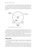
Figure 11. Airflow through the Chassis . . . . . . . . . . . . . . . . . . . . . . . 16
Figure 12. Power Supply Venting . . . . . . . . . . . . . . . . . . . . . . . . . . . . 18
vi
AMD Thermal, Mechanical, and Chassis Cooling Design Guide 23794H—November 2002
List of Tables vii
23794H—November 2002 AMD Thermal, Mechanical, and Chassis Cooling Design Guide
List of Tables
Table 1. Socketed Processor Specifications for the
AMD Athlon™ Processor Model 6 . . . . . . . . . . . . . . . . . . . 3
Table 2. Socketed Processor Specifications for the
AMD Athlon™ Processor Model 8 . . . . . . . . . . . . . . . . . . . 4
Table 3. Socketed Processor Specifications for the
AMD Duron™ Processor Model 7 . . . . . . . . . . . . . . . . . . . . 4
Table 4. General Socketed Thermal Solution Design Target
for the AMD Athlon™ Processor Model 6 . . . . . . . . . . . . . 5
Table 5. General Socketed Thermal Solution Design Target
for the AMD Athlon™ Processor Model 8 . . . . . . . . . . . . . 5
Table 6. General Socketed Thermal Solution Design Target
for the AMD Duron™ Processor . . . . . . . . . . . . . . . . . . . . . 6
Table 7. Suggested Thermal Interface Materials . . . . . . . . . . . . . . 6
viii List of Tables
AMD Thermal, Mechanical, and Chassis Cooling Design Guide 23794H—November 2002
Revision History ix
23794H—November 2002 AMD Thermal, Mechanical, and Chassis Cooling Design Guide
Revision History
Date Rev Description
November 2002 H
Updated values in Tables 1, 2, 3, 4, 5, and 6, and updated dimensions throughout. Added
Fan Considerations section. Updated PS photos and updated airflow diagram.
March 2002 G
Updated Table 1 and Table 3 for total die size, A
core
, and p
thermal
max values.
January 2002 F
Updated Figure 5, “Motherboard Keepout Area for a Socket A AMD Athlon™ Processor
Heatsink,” on page 11, removing the four mounting holes.
November 2001 E
Added Bergquist, Honeywell, Power Devices, and ShinEtsu to the list of Vendors in Table 7,
“Suggested Thermal Interface Materials,” on page 6.
March 2001 D Corrected Athlon™ and Duron™ processor die sizes in tables 1 and 2 on page 4.
February 2001 C
Corrected Max. Length for heatsink from blank to 60mm, and corrected Min. Length for
heatsink from 60mm to blank in Table 4 and in Table 6.
October 2000 B
■ Added mention of AMD Duron processor in the text and added the following tables and
figures with AMD Duron information: Table 3 on page 4, Table 6 on page 6, and Figure
6 on page 12.
■ Revised “Suggested Interface Materials” on page 6, and Table 7 on page 6.
■ Added Section, "Thermocouple Installation for Temperature Testing" on page 13, and
added Figure 7 through Figure 10.
May 2000 A
Initial release based on AMD Athlon Processor Family Thermal Cooling Requirements
Version 2.1.
x Revision History
AMD Thermal, Mechanical, and Chassis Cooling Design Guide 23794H—November 2002
1
23794H—November 2002 AMD Thermal, Mechanical, and Chassis Cooling Design Guide
AMD Thermal, Mechanical,
and Chassis Cooling Design
Guide
This document specifies performance requirements for the
design of thermal, mechanical, and chassis cooling solutions for
the AMD Athlon™ and AMD Duron™ processors. In addition to
providing design targets, drawings are provided from an
AMD-designed solution meeting the requirements of the
AMD Athlon and AMD Duron processors.
Summary of Requirements
To allow the optimal reliability for AMD Athlon and
AMD Duron processor-based systems, the thermal design
solution should dissipate heat from a theoretical processor
running at a given maximum thermal power. The following
sections specify recommended values for these optimal thermal
parameters. By setting a high-power target, the engineer may
avoid redesigning a point solution heatsink/fan sink, thus
increasing the life of the particular thermal solution.
2 PGA Socket A-Based Processor Thermal Requirements
AMD Thermal, Mechanical, and Chassis Cooling Design Guide 23794H—November 2002
PGA Socket A-Based Processor Thermal Requirements
The first step to achieving proper thermal performance is to
dissipate the heat generated by the processor. This, normally, is
accomplished by use of a heatsink of some design. The
following section includes the specifications required to have a
proper heatsink design for Socket A processors.
Socket Description
Socket A is a PGA socket designed for socketed AMD Athlon™
and AMD Duron™ processors. Figure 1 shows the socket layout.
Note: The figure socket is labeled SOCKET 462, which is
synonymous with the Socket A.
Figure 1. Socket A
Socket A is very similar in form factor to previous sockets, such
as Socket 7. Socket A incorporates additional pins in the inner
portion of the socket. Thus, a thermal solution for Socket A can
leverage preexisting design efforts.
Figure 2 on page 3 details the physical dimensions of Socket A.
PGA Socket A-Based Processor Thermal Requirements 3
23794H—November 2002 AMD Thermal, Mechanical, and Chassis Cooling Design Guide
Figure 2. Dimensions of Socket A
Socket A-Based Processor Specifications
Table 1, Table 2 on page 4, and Table 3 on page 4 list the
thermal specifications of the socketed AMD Athlon and
AMD Duron processors.
Table 1. Socketed Processor Specifications for the AMD Athlon™ Processor Model 6
Symbol Description Max Value Notes
T
die
Maximum die
temperature
90ºC
Total die size Die size
129.26 mm
2
Includes L2 cache
A
core
Core area
105.72 mm
2
Die size not including L2 cache
Form factor Heatsink form factor PGA PGA Socket A form factor
P
thermal
Max processor
thermal power
72.0 W Required supported power
4 PGA Socket A-Based Processor Thermal Requirements
AMD Thermal, Mechanical, and Chassis Cooling Design Guide 23794H—November 2002
General Socketed Design Targets
To maintain the die temperature of the processor below the
maximum T
die
value, certain heatsink design points must be
considered. Table 4 details additional specifications that must
be met for the AMD Athlon processor model 6 to reliably
operate.
Table 2. Socketed Processor Specifications for the AMD Athlon™ Processor Model 8
Symbol Description Max Value Notes
T
die
Maximum die
temperature
90°C For Model 2100+ and below
85°C For Model 2200+ and above
Total die size Die size
80.89 mm
2
Includes L2 cache. For CPUID = 680 only.
84.66 mm
2
Includes L2 cache. For CPUID = 681 only.
86.97 mm
2
Includes L2 cache. For CPUID = 682 only.
A
core
Core area
67.35 mm
2
Die size not including L2 cache.
For CPUID = 680 only.
71.12 mm
2
Die size not including L2 cache.
For CPUID = 681 only.
73.43 mm
2
Die size not including L2 cache.
For CPUID = 682 only.
Form factor Heatsink form factor PGA PGA Socket A form factor
P
thermal
Max processor
thermal power
68.4 W Required supported power
Table 3. Socketed Processor Specifications for the AMD Duron™ Processor Model 7
Symbol Description Max Value Notes
T
die
Maximum die
temperature
90ºC
Total die size Die size
105.68 mm
2
Includes L2 cache
A
core
Core area
99.61 mm
2
Die size not including L2 cache
Form factor Heatsink form factor PGA PGA Socket A form factor
P
thermal
Max processor
thermal power
60.0 W Required supported power
Table 4. General Socketed Thermal Solution Design Target for the AMD Athlon™ Processor Model 6
Symbol Description Min Max Notes
PGA Socket A-Based Processor Thermal Requirements 5
23794H—November 2002 AMD Thermal, Mechanical, and Chassis Cooling Design Guide
Table 5 details additional specifications that must be met for
the AMD Athlon processor model 8 to reliably operate.
L Length of heatsink 63 mm
Measurements are for the entire
assembly, including attached fan.
W Width of heatsink 60 mm 80 mm
H Height of heatsink 64 mm
CFM Fan airflow 16 cfm Minimum 16 cfm airflow
m
HS
Mass of heatsink 300 g
F
clip
Clip force 12 lb 24 lb
Typical F: 14 lb≤ F ≤18 lb
Nominal F = 16 lb
T
A
Inside the box local
ambient temperature
42ºC
Table 4. General Socketed Thermal Solution Design Target for the AMD Athlon™ Processor Model 6
Table 5. General Socketed Thermal Solution Design Target for the AMD Athlon™ Processor Model 8
Symbol Description Min Max Notes
L Length of heatsink 63 mm
Measurements are for the entire
assembly, including attached fan.
W Width of heatsink 60 mm 80 mm
H Height of heatsink 64 mm
CFM Fan airflow 16 cfm Minimum 16 cfm airflow
m
HS
Mass of heatsink 300 g
F
clip
Clip force 12 lb 24 lb*
Typical F: 18 lb ≤ F ≤ 22 lb
Nominal F = 20 lb
T
A
Inside the box local
ambient temperature
42ºC
Notes:
* Clip force as high as 30 lb is acceptable if using a 6-tab clip.
6 PGA Socket A-Based Processor Thermal Requirements
AMD Thermal, Mechanical, and Chassis Cooling Design Guide 23794H—November 2002
Table 6 shows the thermal solution design target for the
AMD Duron processor.
Suggested Interface Materials
AMD evaluates thermal interface materials for socketed
designs. A list of suggested materials tested by AMD is
provided in Table 7. If the heatsink needs to be removed, the
phase change material must be replaced on the heatsink before
re-installing the heatsink. Use a plastic scraper to gently
remove the old phase change material from the heatsink.
Sample Socket A Heatsink Drawings
Figure 3 provides a reference drawing of a heatsink AMD has
designed to work with Socket A processors.
Table 6. General Socketed Thermal Solution Design Target for the AMD Duron™ Processor
Symbol Description Min Max Notes
L Length of heatsink 63 mm
Measurements are for the entire
assembly, including attached fan.
W Width of heatsink 60 mm 80 mm
H Height of heatsink 64 mm
CFM Fan airflow 16 cfm Minimum 16 cfm airflow
m
HS
Mass of heatsink 300 g
F
clip
Clip force 12 lb 24 lb
Typical F: 14 lb ≤ F ≤ 18 lb
Nominal F = 16 lb
T
A
Inside the box local ambient
temperature
50º C
Table 7. Suggested Thermal Interface Materials
Vendor Interface Material Material Type
Bergquist HF225UT Phase Change
Chomerics T725 Phase Change
Honeywell PCM45 Phase Change
Power Devices Powerfilm Phase Change
ShinEtsu PCS-TC-11T-13 Phase Change
Thermagon T-pcm905C Phase Change
PGA Socket A-Based Processor Thermal Requirements 7
23794H—November 2002 AMD Thermal, Mechanical, and Chassis Cooling Design Guide
Figure 3. Sample Drawing of Socket A Heatsink
Socket A Heatsink Design Considerations
Heatsink design considerations include the characteristics of
the heatsink itself, the clip used to hold the heatsink to the
processor, the thermal interface material between the heatsink
and the processor, and the length of the fan wire for active
heatsinks.
Heatsink Considerations
The important design parameters of the socket A heatsink
include the dimensions of the flat base, the maximum base
footprint, and the clearance over the socket cam.
Flat base to contact support pads. The PGA processor is housed in a
50 x 50 mm ceramic package. The heatsink makes direct contact
with the flip-chip die. While the die dimensions are
considerably less than the 50 mm x 50 mm package footprint,
the heatsink base must maintain a minimum flat surface of
46 mm x 46 mm centered on the package and 48 mm x 48 mm at
a maximum. This positioning is required for the heatsink to
make contact with compliant load support pads. The pads
protect the die from mechanical damage during heatsink
Measurements are in millimeters
8 PGA Socket A-Based Processor Thermal Requirements
AMD Thermal, Mechanical, and Chassis Cooling Design Guide 23794H—November 2002
installation, as well from shock and vibration. Figure 4 details
the ceramic package and compliant load support pads.
Figure 4. Heatsink and Load Pads
Maximum base footprint of 63 mm x 80 mm. The maximum base
footprint for socket heatsinks is 63 mm x 80 mm (as detailed in
Figure 3 on page 7). Not all processor speeds require the full
63 mm x 80 mm footprint. Heatsinks with approximately 60 mm
x 60 mm footprints have proven to be adequate for low to
moderate clock frequencies.
Clearance in heatsink base for socket cam box. The heatsink base must
have enough clearance so that it does not contact the cam box
on the socket. The clearance zone is defined in the example
shown in the Figure 3 on page 7 and Figure 4.
Clip Considerations
The important design parameters of the socket A heatsink clip
include the load applied to the heatsink, where the load is
applied, how the clip ensures the location of the heatsink in
relation to the processor package and socket, and ease of
installation.
TM
PGA Socket A-Based Processor Thermal Requirements 9
23794H—November 2002 AMD Thermal, Mechanical, and Chassis Cooling Design Guide
Load target of 16 lb with range of 12–24 lb. The clip load is greater
than that allowed for previous processors with similar
mechanical form factors. Table 4 on page 4 details the clip force
requirements.
Load applied directly over center of die (asymmetric design). To ens ure
adequate thermal interface performance between the flip-chip
die and the heatsink, the clip must apply its load to the heatsink
along a single contact axis. The load should be applied 26.8 mm
from the front (non-cam side) socket tab load point (see
Figure 4 on page 8). The acceptable tolerance for off-center clip
load is ± 1.5 mm.
Feature to lock relative position of heatsink, clip, and socket. A locking
feature is needed to avoid incorrect placement of the heatsink
on the package. Such a lock can be constructed with small tabs
that project from the sides of the clip and fit into a heatsink
channel.
Installation features designed to minimize operator fatigue. The clip load
requirements of the socketed processor are significantly higher
than past models. Emphasis should be focused on providing a
clip design that is easily installed. While clips that do not
require tools for installation offer some advantages, designs
that accept a flat-head screwdriver (or nutdriver) near the clip
hook have certain advantages. Such advantages include the
ability to pry the clip hook over the socket tab during
installation and the ability to install the clips onto the tabs in
areas that are tightly confined by motherboard components
surrounding the socket.
Thermal Interface Considerations
Many customers have indicated a preference for pre-applied
thermal interface materials. A heatsink vendor that chooses to
offer pre-applied interface materials should apply a 25 x 25 mm
pad centered 25 mm from the front edge of the heatsink.
10 PGA Socket A-Based Processor Thermal Requirements
AMD Thermal, Mechanical, and Chassis Cooling Design Guide 23794H—November 2002
Fan Considerations
An active heatsink design incorporates a fan mounted to the
heatsink. To ensure that the heatsink fan wire can reach power
connectors on all Socket 462-based boards, the fan wire length
should be at least 8 inches.
Socketed Motherboard Restrictions
The motherboard design and layout must meet certain
restrictions to ensure that the socketed thermal solution does
not impede the performance of components on the
motherboard. To maintain adequate airflow around the
microprocessor, certain areas on the motherboard must be free
of projecting components. Figure 5 on page 11 shows these
keepout areas on the motherboard for an AMD Athlon
processor, and Figure 6 on page 12 shows the motherboard
keepout area for an AMD Duron processor.
PGA Socket A-Based Processor Thermal Requirements 11
23794H—November 2002 AMD Thermal, Mechanical, and Chassis Cooling Design Guide
Figure 5. Motherboard Keepout Area for a Socket A AMD Athlon™ Processor Heatsink
4
2
3
12 PGA Socket A-Based Processor Thermal Requirements
AMD Thermal, Mechanical, and Chassis Cooling Design Guide 23794H—November 2002
Figure 6. Motherboard Keepout Area for a Socket A AMD Duron™ Processor Heatsink
Thermocouple Installation for Temperature Testing 13
23794H—November 2002 AMD Thermal, Mechanical, and Chassis Cooling Design Guide
Thermocouple Installation for Temperature Testing
To install a thermocouple to measure the operating
temperature of the heatsink, perform the following procedure:
1. Mark a location on the base of the heatsink as shown in
Figure 7. Determine the position of the thermocouple hole
using the following measurements:
• a = 24.765 mm
• b = caliper measurement
• If the heatsink extends over the PGA processor (as it is
diagrammed), then x = a + b
• If the heatsink does not extend over the PGA processor,
then x = a – b
• y = 2 mm
Figure 7. Measuring Thermocouple Position
Die
Drill hole
14 Thermocouple Installation for Temperature Testing
AMD Thermal, Mechanical, and Chassis Cooling Design Guide 23794H—November 2002
2. Drill a hole at the marked location using a #53 drill bit
(1.5113 mm or 0.0595 inches). If the heatsink is symmetric
in relation to the processor package, drill to a depth of half
the width of the heatsink. If it is not symmetrical to the pro-
cessor, drill to a depth that is directly over the center of the
die, as shown in Figure 8.
Figure 8. Bottom View of Heatsink and Drill Depth
Thermocouple Installation for Temperature Testing 15
23794H—November 2002 AMD Thermal, Mechanical, and Chassis Cooling Design Guide
3. Inject thermal grease into the newly drilled hole with a
syringe as shown in Figure 9. Use Dow Corning 340 white
thermal grease or it’s equivalent.
Figure 9. Injecting Thermal Grease into Drilled Hole
4. Gently insert the thermocouple into the hole until it bot-
toms out, and tape it down with Kapton tape, making sure
not to kink the thermocouple. Figure 10 shows an installed
thermocouple.
Figure 10. Installed Thermocouple