PTCsteel a tool to design steel structure according to Australian standard AS4100 Scientific research topic
Bạn đang xem bản rút gọn của tài liệu. Xem và tải ngay bản đầy đủ của tài liệu tại đây (2.5 MB, 26 trang )
SWINBURNE UNIVERSITY OF TECHNOLOGY
MELBOURNE, AUSTRALIA
FACULTY OF SCIENCE, ENGINEERING AND TECHNOLOGY
SCHOOL OF ENGINEERING
DEPARTMENT OF CIVIL AND CONSTRUCTION ENGINEERING
Master of Engineering (Civil)
HES6198 – Research Paper
PCTSteel – A tool to design steel structure according to
Australian Standard AS4100
Instructor: Professor Emad Gad
Student: Cao Thanh Pham - 6657656
Table of Contents
1.
Introduction ....................................................................................................................... 2
2.
Literature review ............................................................................................................... 2
2.1.
Design models ............................................................................................................. 2
2.1.1.
Design for bending moment ............................................................................... 2
2.1.2.
Design for axial compression ............................................................................. 3
2.1.3.
Design for axial tension ...................................................................................... 4
2.1.4. Design for combined actions of bending and compression and bending and
tension 4
2.2.
Software available ...................................................................................................... 6
3.
Specific design model for non-standard I section .......................................................... 7
4.
Developing of PCTSteel tool and its features .............................................................. 10
5.
Validation and limitation ............................................................................................... 13
6.
5.1.
Compare with hand computation ........................................................................... 13
5.2.
PCTSteel charts compare to AISC charts ............................................................. 13
5.3.
Limitation of PCTSteel tool .................................................................................... 14
Conclusion ....................................................................................................................... 14
References................................................................................................................................. 15
APPENDIX
A ....................................................................................................................... 16
APPENDIX B ........................................................................................................................... 20
APPENDIX C ........................................................................................................................... 21
APPENDIX D .......................................................................................................................... 23
HES6198 – Research Paper
Master of Engineering (Civil)
1. Introduction
Structural steel is becoming more popular in construction industry because of its usefulness,
such as a large bearing capacity and high reliability, light weight, portability during transport
and assembly, highly industrialization, and sealed, waterproof. Structural steel is suitable for
use in structural frame or roof for projects with large span and requires high durability, such as
structural frame for industrial factories, roof of stadiums, hangars, and so forth.
Design of steel structure can be done manually by hand computation but with this way designer
would take much time to perform and repeat the calculation steps until achieving the final
results. Design of structures by using computer has appeared many years ago, and there are
many overall software of structural design, and particular for design of steel structure, such as
SAP2000, STAAD.Pro, Midas Gen, Tekla, etc. The software help to optimize the time of
structural analysis and design. The benefits of the software are not small but user is hardly to
using them popular because they are commercialized with high cost and have copyright to use.
To solve the above problem, a design tool of steel structure is developed on a spreadsheet which
will bring the economic and time efficiency for designers or companies by using it. This study
introduces a compact spreadsheet which is called “PCTSteel” using to design the steel structure
according to Australian Standard AS4100 with several design features, for instance designing
capacity of bending, compression, tension, and combined actions of bending and compression
and bending and tension of many sections. At the moment, this design tool covers the designing
of bearing capacity for standard hot rolled sections as UB, UC, WB, WC, PFC, and EA with
the grades of 300 and 350, and non-standard I sections.
2. Literature review
2.1. Design models
AS4100 sets out minimum requirements for the design, fabrication, erection, and modification
of steelwork in structures in accordance with the limit states design method.
This standard is intended to apply also to roadway, railway, and pedestrian bridges. However,
the requirements given in this standard may not always be sufficient for bridge applications. In
these circumstances, the specifications of the relevant Authority shall be used.
Below is the design procedure of steel structure of bending, tension, compression, and
combined actions of bending and tension and bending and compression.
2.1.1. Design for bending moment
Section moment capacity Ms:
Ms = fyZe
Where,
(1)
fy = yield stress used in design
Ze = effective section modulus
Member moment capacity Mb:
Student: Cao Thanh Pham - 6657656
Page 2
HES6198 – Research Paper
Master of Engineering (Civil)
Mb = αmαsMs
Where,
(2)
αm = moment modification factor for bending
αs = slenderness reduction factor
𝑀
𝑀
𝛼 = 0.6
Where,
𝑀
𝑀
(3)
Mo = reference elastic buckling moment for a member subject to
bending:
𝑀 =
Where,
+3 −
𝜋 𝐸𝐼
𝑙
𝐺𝐽 +
𝜋 𝐸𝐼
𝑙
(4)
E = young’s modulus of elasticity, 200 x 103MPa
G = shear modulus of elasticity, 80 x 103
J = torsion constant for a cross-section
Iy = second moment about the cross-section minor principal y-axis
Iw = warping constant for a cross-section
le = effective length
2.1.2. Design for axial compression
Section capacity Ns:
Ns = kfAnfy
Where,
(5)
kf = form factor for members subject to axial compression
An = net area of a cross-section
Member capacity for buckling Nc:
Nc = αcNs
Where,
(6)
αc = compression member slenderness reduction factor
𝛼 = 𝜉 1− 1−
90
𝜉𝜆
+1+𝜂
𝜉=
(7)
(8)
2
Student: Cao Thanh Pham - 6657656
Page 3
HES6198 – Research Paper
Master of Engineering (Civil)
𝜆 = 𝜆 + 𝛼 𝛼 (9)
𝜂 = 0.00326(𝜆 − 13.5) ≥ 0
𝜆 =
𝛼=
𝑙
𝑟
𝑓
250
𝑘
(10)
(11)
2100(𝜆 − 13.5)
𝜆 − 15.3𝜆 + 2050
(12)
2.1.3. Design for axial tension
The nominal section capacity of a tension member shall be taken as the lesser of:
Gross yielding:
Nty = Agfy
(13)
Fracture:
Ntf = 0.85ktAnfu
(14)
Where,
Ag = gross area of a cross-section.
An = net area of a cross-section.
kt = correction factor for distribution of forces in a tension member.
fu = tensile strength used in design.
2.1.4. Design for combined actions of bending and compression and bending and
tension
* Section capacity:
-
Nominal section moment capacity reduced by axial force about major principal x-axis,
Mrx:
𝑀
Where,
=𝛺 𝑀
1−
𝑁∗
∅𝑁
≤𝑀
(15)
N* = design axial force compressive
Ø = 0.9, the capacity factor
𝛺 = the ratio, 𝛺 = 1.18 for doubly symmetric I-sections which
are compact and kf = 1, and 𝛺 = 1 for the others type.
-
Nominal section moment capacity reduced by axial force about minor principal y-axis,
Mry:
𝑀
=𝑀
Student: Cao Thanh Pham - 6657656
1−
𝑁∗
∅𝑁
(16)
Page 4
HES6198 – Research Paper
Master of Engineering (Civil)
Alternatively, for doubly symmetric I-sections which are compact, Mry is calculated by the
following as appropriate:
𝑀
= 1.19𝑀
∗
1−
∅
≤𝑀
(17)
Biaxial bending for compression and tension:
𝑀∗
𝑁∗
𝑀∗
+
+
≤1
∅𝑁
∅𝑀
∅𝑀
(18)
Alternatively, for doubly symmetric I-sections which are compact, section at all points along
the member shall satisfy:
𝑀∗
+
∅𝑀
𝑀∗
∅𝑀
𝑁∗
𝛾 = 1.4 +
∅𝑁
≤1
≤2
(19)
(20)
* Member capacity:
-
In-plane capacity – elastic analysis:
For compression members:
𝑀 =𝑀 1−
𝑁∗
∅𝑁
(21)
𝑀 =𝑀
𝑁∗
∅𝑁
(22)
For tension members:
-
1−
Out-of-plane capacity:
For compression members:
𝑀
𝑁∗
1−
∅𝑁
=𝑀
(23)
For tension members:
𝑀
=𝑀
1+
𝑁∗
∅𝑁
≤𝑀
(24)
* Biaxial bending member moment capacity:
For compression members:
𝑀∗
Ø𝑀
.
𝑀∗
+
Ø𝑀
Student: Cao Thanh Pham - 6657656
.
≤1
(25)
Page 5
HES6198 – Research Paper
Where,
Master of Engineering (Civil)
Mcx = the lesser of the nominal in-plane member moment capacity (M ix)
and the nominal out-of-plane member moment capacity (Mox) for
bending about the major principal x-axis.
For tension members:
𝑀∗
Ø𝑀
Where,
2.2.
.
+
𝑀∗
Ø𝑀
.
≤1
(26)
Mtx = the lesser of the nominal section moment capacity (Mrx) reduced
axial tension and the nominal out-of-plane member moment capacity
(Mox)
Software available
Currently, there are many software solutions for structural design in the market which included
the design of steel structure. The popular software are known as SAP2000, Midas Gen,
STAAD.Pro, and Tekla. Each of software has the significant advantages and disadvantages
In 1970, Professor Edward L. Wilson and colleagues have launched the first version of SAP.
And, now it is developing by the Computers & Structures (CSI), USA. The latest version of
SAP is SAP2000 v15.0.1. SAP200 analyses the structure based on the finite element method.
It has the ability to set many different types of structures, such as steel structures, aluminum
structures, and reinforced concrete structures. The complicated structures such as cable-stayed
bridges, skyscrapers, off shore structures can be designed by this software. By integrating many
design features in a software, it is sometimes difficult to use for user, or user need to undergo a
training course to understand how to use the software. Also, cost and copyright issues are a
major obstacle for user who wants to access this software.
Similar to SAP2000 software, Midas Gen and STAAD.Pro software are two other professional
software for structural design, using the finite element method in structural analysis. Both
software are also designing many different types of structure from complexity to simple. Midas
Gen was developed by Midas Company in 1989 in North Korea, and used for commercial work
in 1996. Version 6.3.2 is the latest version of Midas Gen. STAAD.Pro software was first
developed by Research Engineers International Company in Yorba Linda, California, USA.
Then it was acquired and developed by Bentley Systems Company, USA until now. The latest
version of STAAD.Pro is STAAD.Pro V8i. This software can also design many different types
of structure including concrete, reinforced concrete, steel, and aluminum.
Tekla is a software of Tekla Corporation, Finland. The remarkable feature of this software
compared with others software that are the ability of automatically design and export the
structural design drawings. Tekla is specialized software use for structural steel design, it is
suitable for structural design of industrial factory steel frames and prefabricated steel buildings.
In addition, it also adds the features for structural design of reinforced concrete and precast
concrete.
The above software have outstanding features, depending on the job requirements and habit of
using, user will choose a suitable software to use. However, these software are commercial
Student: Cao Thanh Pham - 6657656
Page 6
HES6198 – Research Paper
Master of Engineering (Civil)
software with high cost. So, it is not popular for using of individual user or small construction
companies, especially students. For instant, a simple design tool of steel structure names “Steel
Design” developed by Digital Canal that has the price of $395. So that, developing a computer
program of steel structural design above user is helpful.
3. Specific design model for non-standard I section
For standard sections, the sections properties can be found from the tables in AISC Volume 1:
Open Sections or from the Onesteel Section Category software. However, for non-standard
section the section properties have to be calculated by hand computation.
The calculations of the non-standard I sections properties are presented below.
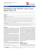
Figure 1 – Non-standard I sections
Determine the centroid of a cross-section:
The I section is divided to three small sections which showed in Figure 1.
Assume the area of small section 1, 2, 3 are A1, A2, A3, and the coordinates corresponding
of these section centroids to the centroid C of the whole section is (x 1, y1), (x2, y2), (x3, y3).
Where, C is the centroid of the cross-section, the C coordinates are determined as follow:
𝑋 =
∑
𝑌 =
Where,
(𝑥 𝐴 )
∑ 𝐹
∑
(𝑦 𝐴 )
∑ 𝐹
(27)
(28)
Ai = the area of i-th section.
Student: Cao Thanh Pham - 6657656
Page 7
HES6198 – Research Paper
Master of Engineering (Civil)
xi, yi = the coordinates of i-th section compare to an assumed datum-line of the
whole section (xo, yo).
Determine second moment of area of a cross-section, I:
For case 1 of Figure 1:
𝐼 =
𝑏 𝑡
𝑏 𝑡
𝑡 𝑑
+𝐴 𝑦 +
+𝐴 𝑦 +
+𝐴 𝑦
12
12
12
(29)
𝐼 =
𝑏 𝑡
𝑏 𝑡
𝑡 𝑑
+𝐴 𝑥 +
+𝐴 𝑥 +
+𝐴 𝑥
12
12
12
(30)
And work similar for case 2.
Determine the radius of gyration, r:
Where,
𝑟 =
𝐼
𝐴
(31)
𝑟 =
𝐼
𝐴
(32)
Ag is the gross area, Ag = A1 + A2 + A3
Determine the plastic modulus, S:
For case 1 of Figure 1:
𝑆 =
𝑏 𝑑
𝑏 −𝑡
−
4
4
𝑑
𝑆 =
𝑡 𝑏
𝑡 𝑏
𝑑 𝑡
+
+
4
4
4
(33)
(34)
And work similar for case 2.
Determine the elastic modulus, Z:
Where,
𝑍 =
𝐼
𝑦
(35)
𝑍 =
𝐼
𝑥
(36)
x = bf/2, and y = d/2 or y = y1 or y= y3 depend on the cross-section.
Warping constant for a cross-section of I sections, Iw:
Student: Cao Thanh Pham - 6657656
Page 8
HES6198 – Research Paper
Master of Engineering (Civil)
𝐼 =
𝑑 +
+
𝑡 𝑏 𝑡 𝑏
(37)
12 𝑡 𝑏 + 𝑡 𝑏
Determine the section compactness and effective section modulus Z e:
Calculate element slenderness values, λe for each plate element:
𝜆 =
Determine the ratio
𝑓
250
𝑏
𝑡
(38)
for each element, the value of λey reference to table 5.2 of
AS4100.
The whole section slenderness λs is taken to be equal to the λe value for the largest ratio
of
The effective section modulus Ze, is then determined from the following “compactness”
classifications:
λs ≤ λsp compact section
λsp<λs ≤ λsy
non-compact section
λs>λsy slender section
Where,
λsp = λep, λsy = λey which are reference to table 5.2 of AS4100
Compact sections:
Ze = S ≤ 1.5Z
(39)
Non-compact sections:
Ze = Z + cz(Zc – Z)
(40)
𝑐 =
(41)
Where,
Slender sections:
-
Section
elements
having
𝜆
𝑍 =𝑍
(42)
𝜆
uniform
compression:
-Section with slenderness determined by a stress gradient in plate
elements with one edge unsupported in compression:
𝑍 =𝑍
𝜆
𝜆
(43)
Determine the form factor, kf:
𝐴
(44)
𝐴
Ag = Σ(biti), gross area of a gross section
Ae = Σ(beiti) ≤ Ag, the effective cross-sectional area,
𝑘 =
Where,
Student: Cao Thanh Pham - 6657656
Page 9
HES6198 – Research Paper
Master of Engineering (Civil)
𝑏 =𝜆
Where,
𝑡
250
≤𝑏
𝑓
(45)
bei is the effective width of the i-th plate element of the section.
λeyi is the plate yield slenderness limit, obtained from table 6.2.4 of
AS4100.
bi is the clear width of a plate element having two plates supporting it
longitudinally from crumpling (the web between the flanges), or the
outstand of the element supported along one longitudinal edge only (the
flange of an open section).
ti and fyi are respectively the thickness and design yield stress of the plate
element being considered.
4. Developing of PCTSteel tool and its features
PCTSteel is developing based on Australian Standard Steel structures, AS4100.
PCTSteel spreadsheet formulas required for the calculation of steel design correspond to
Equations 1 to 45 given above. There must be as many sets of formulas, arranged in rows in the
spreadsheet.
PCTSteel tool covers the steel design of bending, tension, compression, and combined actions
of bending and tension and bending and compression.
This tool is set to calculate the bearing capacity of sections given in the table below:
Grade
Standard 300PLUS
sections
AS3679_1-350
AS3679_2-400
Nonstandard
section
Types of section
UB
UC
UB
UC
WB
WC
WB
PFC
WC
EA
PFC
EA
I-section
Table 1 – Grades and types of section covered in PCTSteel
PCTSteel has three parts of designing:
-
Part 1 is designing of standard sections include UB, UC, WB, WC, PFC.
Part 2 is designing of standard section EA.
Part 3 is designing of non-standard I-section.
PCTSteel is divided to be three parts because there are differences of calculation process of the
sections above.
PCTSteel is using the simple input method which makes it easy and friendly for use. Drop down
selection menu is integrated for easy use and to get the accurate results of calculation process.
Student: Cao Thanh Pham - 6657656
Page 10
HES6198 – Research Paper
Master of Engineering (Civil)
Also, the input messages will help user easy to follow the steps of inputting process. The input
cells are highlight by the dark color to distinguish the input and out cells.
Figure 2 – Input section and support input massage.
Figure 3 – Drop down selection in the input and summary of results in the output.
The summary of results is setting at the first look of output section, which is for quick check of
satisfied or unsatisfied of a chosen section. User just compares the result from input data and
summary of results in the output data to get the most satisfying section. This could be known
as a solution for the economic problem, which is hard and spends a lot of time to do it if
manually calculation by hand.
The top buttons will let user to know where they are in the PCTSteel spreadsheet. These buttons
also use to jump up from this sheet to another sheet. For instant, the Figure 4 below shows that,
user is staying in the calculating of bending of standard sections by look buttons by the red
highlight. If user clicks one of any upon buttons it will move to calculate for the other tasks like
tension of standard sections or equal angle sections or non-standard I-section.
Student: Cao Thanh Pham - 6657656
Page 11
HES6198 – Research Paper
Master of Engineering (Civil)
Figure 4 – Support buttons for switching between the calculation tasks.
The output data is showing the results of calculation and the correlative formulas. This output
type will help users easy to follow step by step how the results coming out and can recheck
manually by hand computation.
Figure 5 – The illustrative output data
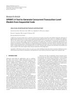
Beside the features above, PCTSteel tool is also designed to draw the charts of bending and
compression capacity of any sections including equal angle and non-standard I-section. The
charts are clearly shown the member moment capacity or the compression moment capacity of
the section which is using of design and the design moment load or design compression load
for easer comparison.
Student: Cao Thanh Pham - 6657656
Page 12
HES6198 – Research Paper
Master of Engineering (Civil)
Figure 6 – The member moment capacities and the design moments about X and Y-axis of
610UB125 grade 300
5. Validation and limitation
5.1. Compare with hand computation
Using PCTSteel, user does not take much time to perform the repetitive calculations many times
to be met the suitable section which compares to calculation by hand. User simply enters the
input data and selects the appropriate section for completing the computational task.
For hand computation, it takes a lot of pages of paper for calculating phase. The errors and
mistakes could be occurred during calculating, this leads to get inaccurate results in the final
results.
PCTSteel tool only provides to user a single page of calculation which easy to check and review.
It will take a few minutes of user to finish the calculation and get the results. The calculation
process can also print out for approve design or checker.
5.2.
PCTSteel charts compare to AISC charts
Basically, the charts of design member moment capacity ØMb and design member capacity in
axial compression ØNc present by PCTSteel tool are the same with the charts provided by AISC.
However, the charts from PCTSteel are easier to follow than AISC’s charts because the
PCTSteel’s charts are showing only one currently section.
The comparison of PCTSteel’s chart and AISC’s charts are shown in the Appendix A.
Student: Cao Thanh Pham - 6657656
Page 13
HES6198 – Research Paper
Master of Engineering (Civil)
PCTSteel also allows to show the charts of EA sections and non-standard I-section that is not
presented by AISC book.
The charts of design member moment capacity and design member capacity in axial
compression of EA are show in Appendix B.
The detail of calculation of bending moment capacity and its chart of a non-standard symmetric
I-section are presented in the Appendix C, and the detail of calculation of compression and its
chart are shown in Appendix D.
5.3.
Limitation of PCTSteel tool
Despite its advantages, PCTSteel tool still has some limitations of using. It cannot automatically
calculate the effective length le, lex, ley, as well as the value of αm, αb, and kt. So, user has to
manually calculate or reference to the table to determine these values.
Besides that, the PCTSteel currently applies only to calculate for the elements of the structure
which was analyzed by the elastic method.
6. Conclusion
PCTSteel provides a very convenient aid for the design of bending, tension, compression, and
combined actions between bending and tension and bending and compression for steel
structure. PCTSteel has significant advantages over showing step by step of calculation process
and providing the charts.
PCTSteel has an important advantage over conventional computer programs, in that they give
a good insight into the effect of the various design parameters. The result of any change in the
trial design is instantly observed because of the automatic recalculation by the spreadsheet. This
encourages the designer to adjust the input data to achieve better design solutions. Optimization
by simple search can thus be undertaken rapidly and efficiently with the PCTSteel.
Instant display of the effect of changes in input data also has an important educational benefit.
The user of the PCTSteel rapidly builds up an understanding of underlying structural behavior
and an intuition for the design situation. This can be of particular value in the classroom. The
option of graphic representation of input and output is of course available in most modern
spreadsheet packages.
With computer facilities now available to almost all structural design engineers, PCTSteel
provides an improved means for increasing design efficiency. The use of traditional hand
calculation is made obsolete by properly prepared spreadsheet templates.
An economic solution is also provided by PCTSteel tool.
However, PCTSteel still has the limitations and need to improve more features to design a
variety of structures, as well as add more computation of bearing capacity of structures, such
as shear capacity and deflection of structure, and add more sections.
Student: Cao Thanh Pham - 6657656
Page 14
HES6198 – Research Paper
Master of Engineering (Civil)
References
Australian Standard, 1998, Australian Standard: Steel Structures, AS 4100, NSW,
AUS.
Australian Institute of Steel Construction, 1994, Design capcity tables for structural
steel – Volume 1: Open Sections, 2nd edn, New South Wales, AUS.
Australian Institute of Steel Construction, 1992, Worked examples for steel
structures: Worked design examples for steel structures according to strength limit
state of AS4100-1990, 2nd edn, New South Wales, AUS.
Gorenc, B, Tinyou, R, Syam, A 2009, Steel designers’ handbook, 7th edn, UNSW
Press, New South Wales, AUS.
Standards Australia, 1999, Steel structures design handbook (HB 48 -1999), 2nd
end, New South Wales, AUS.
Madugula, MKS, Kennedy JB 1985, Single and compound angle members, Elsevier
applied science publishers LTD, USA.
Bauer, DB 1997, Calculation of the Plastic Section Modulus Using the Computer,
Engineering Journal, Third quarter, pp 104 – 107.
Kirke, B, Al-Jamel, IH 2004, Steel Structures Design Manual To AS 4100, 1st end,
Queensland, AUS.
Computers & Structures website, < />
MIDAS Company website,
< />
Tekla website, < />
Student: Cao Thanh Pham - 6657656
Page 15
HES6198 – Research Paper
Master of Engineering (Civil)
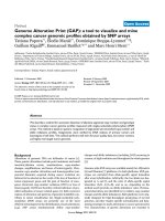
APPENDIX A
Comparison the PCTSteel’s charts and the AISC’s charts for UB section grade 300
Figure A1 - Design member moment capacity ØMbx (kNm) of Universal beam grade 300,
610UB125 provided by PCTSteel.
Student: Cao Thanh Pham - 6657656
Page 16
HES6198 – Research Paper
Master of Engineering (Civil)
Figure A2 – Design member moment capacity ØMb (kNm) of Universal beam grade 300
provided by AISC book.
Student: Cao Thanh Pham - 6657656
Page 17
HES6198 – Research Paper
Master of Engineering (Civil)
Figure A3 - Design member capacity in axial compression ØN c (kN) about x-axis and yaxis of Universal beam section 610UB125 grade 300 provided by PCTSteel.
Student: Cao Thanh Pham - 6657656
Page 18
HES6198 – Research Paper
Master of Engineering (Civil)
Figure A4 – Design member capacity in axial compression ØNc (kN) of Universal beam
grade 300 provided by AISC book.
Student: Cao Thanh Pham - 6657656
Page 19
HES6198 – Research Paper
Master of Engineering (Civil)
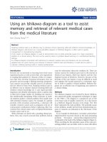
APPENDIX B
The charts of a steel Equal Angle section
Figure A1 – Design member moment capacity ØMb about X-axis and Y-axis of equal angle
150x150x12 EA grade 300
Figure B2 – Design member capacity in axial compression ØNc about X-axis and Y-axis of
the equal angle section 150x150x12 EA grade 300.
Student: Cao Thanh Pham - 6657656
Page 20
HES6198 – Research Paper
Master of Engineering (Civil)
APPENDIX C
Detail of calculation for bending and the charts of a non-standard symmetric I-section
Student: Cao Thanh Pham - 6657656
Page 21
HES6198 – Research Paper
Student: Cao Thanh Pham - 6657656
Master of Engineering (Civil)
Page 22
HES6198 – Research Paper
Master of Engineering (Civil)
APPENDIX D
Detail of calculation for compression and the charts of a non-standard unsymmetrical Isection
Student: Cao Thanh Pham - 6657656
Page 23
HES6198 – Research Paper
Student: Cao Thanh Pham - 6657656
Master of Engineering (Civil)
Page 24