Modeling Indirect Lightning Strikes for Railway Systems With Lumped Components and Nonlinear Effects
Bạn đang xem bản rút gọn của tài liệu. Xem và tải ngay bản đầy đủ của tài liệu tại đây (721.84 KB, 4 trang )
IEEE TRANSACTIONS ON ELECTROMAGNETIC COMPATIBILITY, VOL. 53, NO. 1, FEBRUARY 2011
[16] A. Shoory, R. Moini, H. Sadeghi, and V. A. Rakov, “Analysis of lightningradiated electromagnetic fields in the vicinity of lossy ground,” IEEE
Trans. Electromagn. Compat., vol. 47, no. 1, pp. 131–145, Feb. 2005.
[17] R. Moini, B. Kordi, G. Rafi, and V. A. Rakov, “A new lightning return stroke model based on antenna theory,” J. Geophys. Res., vol. 105,
no. D24, pp. 29693–29702, Dec. 2000.
[18] V. Javor, “Approximating decaying part of the lightning return stroke
channel-base current,” in Proc. 3rd Int. Symp. Lightning Phys. Effects,
Vienna, Austria, Apr. 2008, pp. 26.
[19] D. M. Velickovic and S. R. Aleksic, “A new approximation of pulse
phenomena,” (in Serbian), in Proc. 2nd Serbian Symp. Appl. Electrostatics
IIEC1986, Nis, Serbia, Nov. 1986, pp. 6.1–6.9.
[20] V. Javor and P. D. Rancic, “Application of one suitable lightning returnstroke current model,” in Proc. Eur. Int. Symp. Electromagn. Compat. Eur.
2006, Barcelona, Spain, Sep. 2006, pp. 941–946.
[21] Protection Against Lightning—Part I: General Principles, IEC Standard
62305-1, 2006.
[22] F. Heidler, W. Zischank, Z. Flisowski, Ch. Bouquegnau, and C. Mazzetti,
“Parameters of lightning current given in IEC 62305-background, experience and outlook,” presented at the 29th Int. Conf. Lightning Protection,
Uppsala, Sweden, Jun. 2008.
[23] V. Javor, “New functions for IEC 62305 standard lightning currents,”
presented at the Int. Conf. Lightning Protection ICLP, Cagliari, Italy, Sep.
2010, pp. 1066-1–1066-5.
[24] V. Javor and P. D. Rancic, “On the choice of the lightning channel current
decay constant in the modified transmission line model with exponential
decay,” J. Commun., Softw. Syst., vol. 5, no. 4, pp. 135–139, Dec. 2009.
[25] V. Javor and P. D. Rancic, “Electromagnetic field in the vicinity of lightning
protection rod at a lossy ground,” IEEE Trans. Electromagn. Compat.,
vol. 51, no. 2, pp. 320–330, May 2009.
I. INTRODUCTION
A model with most common devices connected along multiconductor transmission line (MTL) system of Swedish electrified railway
systems, i.e., booster transformers (BTs), autotransformers (ATs), and
track circuits, for evaluating the voltage and current propagation due
to lightning and switching transient sources was developed by the authors [1]. As the potential between above ground wires and poles may
exceed the insulator impulse withstand voltage levels, flashovers occur
and hence needs to be implemented in the model. In this paper, for
indirect lightning strikes [2], we study the effects of these aforementioned lumped components in conjunction with the nonlinear effects
of pole grounding resistances due to soil ionization [3], and line to
pole flashovers [4] on the propagating surge voltages along the MTL
system.
II. INDUCED VOLTAGES ACROSS LUMPED DEVICES ALONG THE
CATENARY TRACK SYSTEM
The electromagnetic interference (EMI) source used in the calculations is representative of a subsequent lightning return stroke. The
lightning is simulated to strike at a 50-m perpendicular distance from
the midpoint of the system. The lightning channel base-current wave
shape, at time t, is expressed by the sum of two functions expressed as
(1), with the parameters as stated in Table I [2]. With these parameter
values, the base-current peak is about 12 kA. This current is assumed
to propagate upward in the lightning channel in accordance with the
modified transmission-line model with linear decay [5], [6]
Modeling Indirect Lightning Strikes for Railway Systems
With Lumped Components and Nonlinear Effects
Z. Mazloom, N. Theethayi, and R. Thottappillil
249
−t
I0 (t/τ1 )n
exp
.
η 1 + (t/τ1 )n
τ2
i (0, t) =
With
η = exp −
Abstract—Induced voltages due to lightning strikes along multiconductor transmission line (MTL) systems terminated with different loads at
line ends have been widely studied by solving telegraphers’ equations using the finite-difference time-domain method. However, MTL systems with
lumped series and shunt-connected devices/components along the lines have
not attracted much attention. There are methods available for introducing
lumped components along MTL systems. In this paper, a method previously developed by the authors will be used to determine induced voltages
across transformers connected to the catenary wire and track-circuit relay
units along the MTL system representative of a Swedish single-track railway system for the case of indirect lightning strikes. Nonlinearities like soil
ionization and insulator flashovers are also considered. It is found that both
the nonlinearities and lumped components together dominate the inducedvoltage amplitude and wave shapes across devices/components.
Index Terms—Crosstalk, power system simulation, transmission-line
modeling.
Manuscript received February 22, 2010; revised May 25, 2010; accepted
June 17, 2010. Date of publication December 10, 2010; date of current version
February 16, 2011. This work was supported by the Swedish National Rail
Administration (Banverket).
Z. Mazloom is with the Department of Science, Islamic Azad University, Mehriz Branch, Mehriz 89818-56571, Iran (e-mail: Mazloom@
iaumehriz.ac.ir).
N. Theethayi is with the Mainline and Metros, Bombardier Transportation, Văasteras, SE-722 14, Sweden (e-mail:
bombardier.com).
R. Thottappillil is with the Division for Electromagnetic Engineering, Royal
Institute of Technology, Stockholm, SE-100 44, Sweden (e-mail: Rajeev.
).
Color versions of one or more of the figures in this paper are available online
at .
Digital Object Identifier 10.1109/TEMC.2010.2072960
(1)
τ1
τ2
n τ2
τ1
1/n
(2)
and I0 as the amplitude of the channel base current, τ 1 and τ 2 as front
and decay time constants, respectively, η as the amplitude correction
factor, and n as an exponent.
The field-to-line coupling model adopted in the calculations is the
Agrawal et al. model [7]. In this model, the electromagnetic fields are
represented as series- and shunt-connected voltage sources along the
lines of the MTL system [2], [7].
In the analysis, an MTL system, representative of the catenary track
system of a Swedish electrified single-track railway system, as shown
in Fig. 1, is considered. As seen, this 6-km long MTL system consists of
five overhead wires, S-rail, I-rail, catenary, return conductor/negative
feeder (called as return conductor), and auxiliary wire. All lines are terminated to the finitely conducting ground (ground resistivity 1000 Ωm)
by their self-characteristic impedance. The conductor radii and characteristic impedances are given in Table II. Characteristic impedances
are calculated for ideal ground, and are only approximate for finitely
conducting ground. The telegraphers’ equation for the 5-conductor
transmission line system above finitely conducting ground is given as
follows:
B
∂V (x, t)
+ AI (x, t) + √
∂x
π
+ Le
∂I (x, t)
+
∂t
0
t
ς (t − τ )
0
∂I (x, t)
∂V (x, t)
+ Ce
= 0.
∂x
∂t
0018-9375/$26.00 © 2010 IEEE
t
1 ∂I (x, t − τ )
√
dτ
τ ∂ (t − τ )
∂I (x, τ )
dτ = Exi (x, h, t)
∂τ
(3a)
(3b)
250
IEEE TRANSACTIONS ON ELECTROMAGNETIC COMPATIBILITY, VOL. 53, NO. 1, FEBRUARY 2011
TABLE I
BASE-CURRENT PARAMETER VALUES
Fig. 3. Interface scheme between the FDTD method and the circuit solver
for solving TL systems that have lumped shunt and series devices at different
locations of the MTL systems [1].
Fig. 1. MTL system representative of a typical railway traction conductor
feeding system used for simulations [1].
TABLE II
CONDUCTOR RADII AND CHARACTERISTIC IMPEDANCES FOR LINE
TERMINATIONS IN FIG. 1
1) Case 1: The MTL system without any components, discontinuities, and nonlinearities.
2) Case 2: The MTL system corresponding to a BT feeding system with track circuits; a BT unit, I-rail discontinuities, pole
grounding resistances, and flashovers.
3) Case 3: The MTL system corresponding to an AT feeding system with track circuits; an AT unit, I-rail discontinuities, pole
grounding resistances, and flashovers.
Poles are located at every 60 m along the MTL system in simulation
cases 2 and 3, not shown in Fig. 1. The voltages across the trackside
transformer windings and the relay units, connected across the tracks,
are investigated.
In Fig. 2, interconnections and grounding points associated with
poles are shown for the case of a BT system. At all the poles, the S-rail
is shorted to the pole and the overhead wires are connected to the poles
by insulators, with impulse withstand voltages as per Table III. The
resistor Rg is the pole-footing resistance, expressed as follows [3], [4]:
Rg (t) =
Ig (t) =
Fig. 2. Insulators, connections, and pole-footing resistance in a single track
BT system (adopted from [4]).
TABLE III
INSULATOR MATERIAL AND WITHSTAND VOLTAGES
R0
1 + IR /Ig
1 E0
.
2π σg R02
(4a)
(4b)
In (4), R0 is the pole-footing resistance measured with low current,
IR is the lightning current flowing through the footing resistance, and
Ig is the current required to produce a soil gradient E0 at which soil
breakdown occurs.
The pole insulator flashovers can be modeled as arcs, as in [4]. But
due to simplicity, in the calculations made in this paper, the flashover
is assumed to form a short-circuit between the pole and the wire as the
voltage across the insulator exceeds the insulator withstand voltage.
The grey waveforms in Figs. 4–9 correspond to voltages obtained
for the same ports/locations in case 1.
In the model, the lumped devices (represented as a circuit model, as
shown in Fig. 3) along MTL systems are solved, as explained in [1]. In
Fig. 3, the circuit is solved using Kirchhoff’s current laws. The voltages
and currents along the MTL are solved using the finite-difference timedomain (FDTD) method.
A. BT and AT Port Voltages
In (3), V and I are the line voltages and currents, respectively, A
and B are constants for taking skin effect into account [8], ς (t) is the
transient ground impedance calculated using the expression in [9], and
E is the horizontal electric field along the line, including the effects of
finitely conducting ground using the Cooray–Rubinstein formula [10].
Using the aforementioned MTL system, three cases will be investigated.
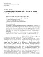
In Fig. 4, it is seen that the voltages across the windings along
the catenary wire side and return conductor side are having similar
magnitudes and are larger compared to corresponding case 1. The oscillatory voltages are due to nonlinearities. On the contrary, comparing
cases 1 and 3 in Fig. 5, it is seen that peak voltages across the AT
windings are comparable with nonlinearities included. Moreover, the
voltages across the AT windings are much higher than the corresponding BT winding cases. It is also seen in Fig. 5 that the transformer
IEEE TRANSACTIONS ON ELECTROMAGNETIC COMPATIBILITY, VOL. 53, NO. 1, FEBRUARY 2011
251
Fig. 7. Voltages appearing across relay units closer to the middle of the line
for cases corresponding to cases 1 (grey) and 3 (black).
Fig. 4. Voltages appearing across BT windings for cases corresponding to
cases 1 (grey) and 2 (black).
Fig. 8. Voltages appearing across relay units closer to the line ends for cases
corresponding to cases 1 (grey) and 2 (black).
Fig. 5. Voltages appearing across AT windings for cases corresponding to
cases 1 (grey) and 3 (black).
winding across the negative feeder to the S-rail is suffering the highest
induced voltage of more than 35 kV. Again, it is seen that the voltage
waveforms are oscillatory.
B. Track-Circuit Port Voltages
Fig. 6. Voltages appearing across relay units closer to the middle of the line
for cases corresponding to cases 1 (grey) and 2 (black).
The induced voltages across the relay units at the middle of the line
are similar for cases 2 and 3 (BT and AT feeding systems, respectively)
and show very oscillatory behavior after a short time, as shown in
Figs. 6 and 7. The peak-induced voltages appearing across the relay
units closer to the ends of the system are similar for cases 2 and 3
(BT and AT feeding systems, respectively) and show comparably less
oscillatory behavior as per Figs. 8 and 9. It is seen that relay unit no. 5 in
the BT system (see Fig. 8, case 2) is suffering the highest voltage peak.
Otherwise, comparing Figs. 6 and 7 with Figs. 8 and 9, in general, the
peak voltages across the relay units in the middle of the line is doubled
compared to the corresponding line end relay units.
252
IEEE TRANSACTIONS ON ELECTROMAGNETIC COMPATIBILITY, VOL. 53, NO. 1, FEBRUARY 2011
[7] A. K. Agrawal, H. J. Price, and S. Gurbaxani, “Transient response of a
multiconductor transmission line excited by a nonuniform electromagnetic
field,” IEEE Trans. Electromagn. Compat., vol. 22, no. 2, pp. 119–129,
May 1980.
[8] C. R. Paul, Analysis of Multiconductor Transmission Lines. New York:
Wiley, 1994.
[9] R. Araneo and S. Celozzi, “Direct time domain analysis of transmission
lines above a lossy ground,” Inst. Elect. Eng., (IEE) Proc. Sci., Meas.
Technol., vol. 148, no. 2, pp. 73–79, Mar. 2001.
[10] F. Rachidi, C. A. Nucci, M. Ianoz, and M. Mazzetti, “Influence of a lossy
ground on lightning induced voltages on overhead lines,” IEEE Trans.
Electromagn. Compat., vol. 38, no. 3, pp. 250–264, Aug. 1996.
The Study On Normalized Site Attenuation With
Reflected Rods
Di Wu and Gang Zhu
Fig. 9. Voltages appearing across relay units closer to the line ends for cases
corresponding to cases 1 (grey) and 3 (black).
III. CONCLUSION
In this paper, it is shown how nonlinearities associated with polefooting resistance and line to pole insulator flashovers, in conjunctions
with lumped series- and shunt-connected devices/components, affect
the induced voltages across components along MTL systems of a typical railway system. It was seen that the flashover occurs mainly at pole
locations up to 300 m away from the MTL system midpoint, closest to
the lightning strike location. It was also seen that the line insulators subjected to flashovers were mainly of the catenary and return conductors.
Depending on the relative position of the lumped device/component
with respect to the lightning position, for the given lightning source
with 12-kA peak current, the peak voltages across the AT windings
can be up to 35 kV compared the case of BT windings which is about
15 kV. The peak voltage across the relay units can be as high as
60 kV. The model (with modifications including more components or
extension to double track systems) can be used as a tool for lightning
protection studies within railway systems.
REFERENCES
[1] Z. Mazloom, N. Theethayi, and R. Thottappillil, “A method for interfacing
lumped-circuit models and transmission-line system models with application to railways,” IEEE Trans. Electromagn. Compat., vol. 51, no. 3,
pp. 833–841, Aug. 2009.
[2] C. A. Nucci, F. Rachidi, M. Ianoz, and C. Mazzetti, “Lightning-induced
voltages on overhead lines,” IEEE Trans. Electromagn. Compat., vol. 35,
no. 1, pp. 75–86, Feb. 1993.
[3] Technical Council of the IEEE Power Engineering Society, IEEE Guide
for the Application of Insulation Coordination, IEEE Standard 1313.2,
1999.
[4] N. Theethayi, Y. Liu, R. Montano, R. Thottappillil, M. Zitnik, V. Cooray,
and V. Scuka, “Theoretical study on the consequence of a direct lightning
strike to electrified railway system in Sweden,” J. Electr. Power Syst. Res.,
vol. 74, pp. 267–280, 2005.
[5] V. Rakov and A. A. Dulzon, “Calculated electromagnetic fields of lightning return strokes,” Tekhnicheskaya Elektrodinamika, vol. 42, no. 1,
pp. 87–89, 1987.
[6] R. Thottappillil, V. A. Rakov, and M. A. Uman, “Distribution of charge
along the lightning channel: Relation to remote electric and magnetic fields
and to return-stroke models,” J. Geophys. Res., vol. 102, pp. 6987–7006,
1997.
Abstract—Standard sites are important for antenna calibrations. However, many actual sites are not perfect for antenna calibrations due to surrounding reflectors and other measurement uncertainties. Earlier studies
were either impractical for actual sites or calculating inaccurately. This paper develops a new method to compute normalized site attenuation (NSA)
with reflectors nearby. Based on the conventional NSA, the model with the
actual rod-like reflectors is formulated by the wave propagation theory,
which is not considered earlier. With this new method, the interferences of
rods are considered from the shortest reflected path. The results of the proposed method show good agreement with the numerical simulation results.
Index Terms—Antennas, attenuation measurement, electromagnetic
compatibility (EMC), moment methods, propagation.
I. INTRODUCTION
Antenna factor (AF) is fundamental for computing the incident electric field strength accurately in EMC tests. Therefore, antennas need
to be calibrated accurately to avoid inaccurate test. However, there
exists a circular problem in antenna calibrations [1] and site validations [2]: antennas need to be calibrated on a standard site that in turn
is validated by the antennas with known AF. Thus, the AF contains
the uncertainty caused by the site it was calibrated on, but the quality
of the site under test can only be known with the uncertainty of the
antenna calibration [3]. The standard test site is the method to solve
this problem [4].
A standard test site should be an open, flat, level area that is clear
of overhead wires and reflecting structures. For assessing an actual
site, it is needed to compare the normalized site attenuation (NSA)
Manuscript received February 10, 2010; revised July 5, 2010; accepted
August 30, 2010. Date of publication October 21, 2010; date of current version February 16, 2011. This work was supported by the Joint Program of the
National Natural Science Foundation of China under Grant 60830001, by the
Key Project of State Key Laboratory of Rail Traffic and Control under Grant
RCS2008ZZ007, and by the Program for Changjiang Scholars and Innovative
Research Team in University under Grant IRT0949.
The authors are with the State Key Laboratory of Rail Traffic Control
and Safety, Beijing Jiaotong University, Beijing, 100044, China (e-mail:
; ).
Color versions of one or more of the figures in this paper are available online
at .
Digital Object Identifier 10.1109/TEMC.2010.2078823
0018-9375/$26.00 © 2010 IEEE