Tài liệu SML Specifi er‘s Manual pdf
Bạn đang xem bản rút gọn của tài liệu. Xem và tải ngay bản đầy đủ của tài liệu tại đây (7.25 MB, 80 trang )
DRAINAGE TECHNOLOGY
SML Specifi er‘s Manual
Düker cast iron drainage pipe systems
for building drainage
L
L
L
t
made
in
Germany
Düker SML Pipe System
2
3
TABLE OF CONTENTS
General Information
page
Application, features, planning,
guarantee and quality 5 – 8
Fire protection 9 – 12
Noise protection 13
Material properties 15
01 SML Delivery Programme
SML pipes and fittings – construction dimensions 17
SML pipes 17
SML reducers 18
SML down pipe supports and bearing rings 18
SML bends 19 – 21
SML offsets/S-bends 22 – 23
Bends combinations 23 – 24
SML branches and installation examples 25 – 29
SML inspection pipes 30
SML plugs 30
SML siphons, installation examples
and combinations 31 – 33
SML rain water stand pipes 33
SML adapter with clamp flange and wall flange 34
SML pipe with wall flange 34
SML roof penetration 34 – 35
SML wash basin connecting bends 36
Rubber connectors 37
WC connectors and connection examples 37 – 41
SML boss pipes 42
SML connectors 42
Connecting SML pipes to other soil pipes 43
02 Couplings Programme
Dükorapid
®
coupling 45
MLetec
®
Rapid coupling 45
Rapid Inox coupling 46
Rapid MSM coupling 46
CV coupling 47
CE coupling 47
CE dual ring coupling 48
Ductile cast iron coupling 48
Connect-F Inox coupling 49
Connect-G Inox coupling 49
Kombi grip collar 50
CV grip collar 50
Düker grip collar 51
02 Couplings Programme
page
Rekord grip collar 51
SVE coupling 52
Düker EK Fix Coupling 52
Konfix Multi coupling 53
Multiquick coupling 53
Transition coupling 54
Düker fire protection link BSV 90 54
SML couplings – fields of application 55
03 Assembly and Installation Instructions
Assembly and installation regulations 57 – 58
Dükorapid
®
coupling 59
Rapid Inox coupling 59
MLetec
®
Rapid coupling 59
Rapid MSM coupling 59
CV/CE coupling 60
Ductile cast iron coupling 60
Connect-F Inox coupling 61
Connect-G Inox coupling 61
Kombi grip collar EK 62
Düker grip collar 62
CV grip collar 62
Rekord grip collar 62
SVE coupling 63
Düker EK Fix Coupling 64
Konfix Multi coupling 64
Multiquick coupling 65
Transition coupling 66
Cutting of pipe ends 67
04 Laying Instructions
Imbedding cast iron pipes in concrete 69
General rules for fixing SML pipes 70 – 71
Flow capacities 72
Aquaperfect
®
siphonic system 74 – 77
Application, Features, Planning
4
APPLICATION, FEATURES, PLANNING
5
Areas of Application
The European standard EN 877 is valid for prefabricated parts of
cast iron pipes for construction - normally as non-pressure pipe-
lines - of building drainage systems as well as connecting drains.
The nominal diameter range covers DN 40 up to and including
DN 600. This standard contains requirements for material,
dimensions and tolerances, mechanical features, composition,
standard coatings for cast iron pipes, fittings and accessories.
Further it contains functional requirements for all prefabrica-
ted parts including couplings. It is valid for pipes, fittings and
accessories which are manufactured by casting process, no
matter which type, or from cast parts, and for the corresponding
couplings. Düker SML drainage pipe systems are in accordance
with this standard and exceed its requirements by far in many
respects. Also the demands of DIN 19522 and ISO 6594 are sur-
passed.
The Material Features
Düker drainage pipe systems are manufactured of grey cast iron
GG according to EN 1561 - type at least EN-GJL-150 (formerly
GG 15 according to DIN 1691) which means an iron and carbon
alloy with high graphite content which is integrated in lamella
form and finely distributed within the metallic base compound.
This Düker-typical crystalline structure gives the material high
strength, wear and temperature resistance, excellent corrosion
resistance, and a very high damping capacity. Düker SML drai-
nage pipes distinguish themselves by robustness, durability, fire
resistance and silent operation – even without special insulation
or soundproofing.
SML Coating
The SML drainage pipes are coated with a reddish brown base
coat on the outside according to the current standard. On the
inside, the pipes are provided with a permanent cross-linked
epoxy coating which distinguishes itself by high resistance
against chemical and mechanical influences. The features of
this high-quality coating go beyond the requirements of EN 877.
This particularly protects Düker SML drainage pipe systems
against domestic effluents which are becoming increasingly
aggressive because of the new regulation that rain water and
waste water must be disposed of separately, which means that
pipe coatings are facing new challenges. The Düker hot perma-
nent mould entrifugal casting process used in the production of
our pipes guarantees a uniform, non-porous interior coating with
fully cross-linked, elastic and epoxy material.
It also makes for an extremely smooth interior surface.
SML fittings are given an interior and exterior dip coating with
high proof cross-linked epoxy.
Planning and Installation
Planning and installation of SML pipelines follow
the technical regulations and stipulations of
• EN 12056 Gravity drainage systems inside buildings
• EN 752 Drain and sewer systems outside buildings
• EN 1610 Construction and testing of drains and sewers
and other applicable European, national or local standards
and regulations.
Applicable Product Standards
Düker SML meets the requirements of
• ISO 6594
• EN 877
• DIN 19522
and other international standards.
6
APPLICATION, FEATURES, PLANNING
Excerpt from the test criteria
Table 1-3. from RAL-GZ 698
Approvals
Düker SML is officially approved in
Australia No. WMKT 20057
Czech Republic No. J-30-20817-04
Finland No. YM 110/6221/2006
France (NF) No. 4/1-01
Germany No. 110001436/01/01
Hungary No. A-725/2004
Norway No. 0401 and 0408
Russia No. POCC DE. E01.B34909
Sweden No. 0041/04
Switzerland No. 23005
Ukraine No. UA1.070.0075668-09
United Kingdom BBA Agrément No. 04/4189
and numerous other countries.
CE Conformity
In 2008, the relevant product standard EN 877
for cast iron drainage pipe systems became a
so-called harmonised standard. This means that
it now contains an annex ZA with details about the product cha-
racteristics and testing required for CE marking.
The manufacturers are now required to apply the CE marking
to their products as per EN 877 in order to confirm the product‘s
suitability for the free trade inside the EU. The CE marking re-
places certain national marks such as the German „Ü“
conformity mark.
The manufacturers have been granted a certain period of time to
organize the new marking. This period may vary between coun-
tries; in Germany it expired on 31 August 2009.
The application of the CE marking must be based on a conformity
declaration issued by the manufacturer. The Düker conformity
declaration can be downloaded from www.dueker.de.
However, unlike former “Ü” mark, the CE marking on cast iron
drainage pipe products is not based on any third-party quality
tests. All tests (with the exception of a fire test for the European
classification „non-combustible“) are carried out and confirmed
only by the manufacturer himself. For this product, the CE mar-
king is not an effective statement about product quality.
GEG Quality Association Cast Iron Drainage
Technology
In order to fulfil the increasing safety
requirements of our partners in plumbing,
trade, planning and authorities, the Euro-
pean cast iron pipe industry as well as
suppliers of accessories founded the IZEG.
IZEG and the integrated quality associati-
on GEG award a RAL quality label to cast iron drainage pipes and
fittings that have passed a number of tests defined in the RAL
GEG quality directives.
Those awarded with the RAL GEG quality label are subject to
an initial test as well as regular third-party surveillance by an
authorized institute. The requirements for this label are consi-
derably higher than those of EN 877, particularly regarding the
resistance of the inside coating. Unlike the CE marking, this qua-
lity label guarantees users a permanently high product quality.
Additional requirements for the testing of interior coatings
Medium/solution concentration pH-value duration
of test
temperature
in °C
Phosphoric acid 25% 1.0 72h 40
Acetic acid 10% 2.0 48h 25
Hydrogene pyroxide solution 10% 3.5 48h 25
Sulphuric acid 0.1 N 1.0 30d 50
Lactic acid 1% 2.0 48h 25
Citric acid 5% 1.5 30d 50
Waste water according to EN 877 7.0 30d 50
Natriumhydrogencarbonat 0.1N 11.4 30d 50
Salt water 5.6 10d 50
(Completely desalted) water 6.4 30d 50
Salt spray 1500h 35
N= normal solution; d=days; h= hours
7
APPLICATION, FEATURES, PLANNING
Cost Considerations
Cost comparisons between SML pipeline systems and alternative
materials must not only compare the cost of pipe per meter. An
evaluation must also consider the following advantages of SML:
• Easy and fast installation with no specialists required;
normal plumber’s skills are sufficient.
• No special equipment required.
• No costly fire protection collars.
• Lower fire insurance premiums.
• Fewer brackets due to superior stability.
• No thermal expansion sockets.
• No calculation of deflection legs with anchored
and sliding fixings.
• Excellent sound absorption, no overall noise insulation
or additional noise protection walls necessary.
• High resistance to positive and negative pressure,
axial restraint up to 10 bar possible, therefore no
need to change material in sensitive areas.
• Lower maintenance costs for damages by use or
vandalism.
• Full recyclability means lower removal costs at the
end of the lifetime of the building.
Düker QM System as per EN ISO 9001:2008
Düker was one of the first companies of the trade to achieve
the ISO 9001 certification and was even awarded the „Bava-
rian Quality Award“ in 1999. This quality award encourages us
to continue doing what we started decades ago: keeping the
quality standard of cast iron drainage pipes at a high level with
continual new ideas, dependable system solutions and first-class
finish of our products.
SML Drainage Pipe Systems - Guarantee
Düker guarantees that the pipes, fittings and couplings supplied
have been manufactured in accordance with the standards
and approvals valid at the time of manufacturing. In the case
of defects, Düker will, during a period of 5 years, replace the
defective parts free of charge. Without specific agreement,
Düker will not accept liability for consequential losses.
SML Drainage Pipe Systems
and Environmental Protection
Grey cast iron - the material from which Düker SML pipes are
manufactured - is 100 % recyclable. Pipe cuttings can be inclu-
ded in the recycling circle without any trouble of waste disposal,
also because the coating is free of benzo(e)pyrene and other
environmentally dangerous chemicals.
8
Fire Protection
9
FIRE PROTECTION
Why Use Cast Iron Drainage Pipe Systems
for Fire Protection?
Non-Combustibility
Düker drainage pipes consist of grey cast iron with lamellar
graphite and are certified to correspond to EN 877.
Annex F of EN 877 says that
Cast iron products in accordance with this European Standard are
non-flammable and non-combustible. When exposed to fire they
will maintain their functional characteristics and integrity for
several hours, i.e. their walls will remain impervious to flames
and gases and there will be no fracture, collapse or significant
deformation. The integrity of connections through walls and cei-
lings is maintained.
In order that the pipeline can be installed openly, the following
conditions must be fulfilled:
• thickness of outer coating no more than 0.5 mm
• minor combustible materials for joints and clamps
are admissible (rubber gaskets)
• pipes must be fixed with metal plugs
• possible insulations must be made of non-combustible
material
Thermal Loads
With Düker drainage pipes it is not necessary to consider thermal
loads - defined as the energy quantity emitted by a material by
combustion. In necessary gangways a maximum of 7 kWh/m
used to be allowed, but the latest German regulations forbid any
thermal load in gangways and escape routes.
For comparison: polyethylene (PE) emits 12 kWh per kg, fuel oil
11.7 kWh per kg.
Smoke Generation
If installed with couplings whose rubber gaskets are completely
covered by stainless steel collars (e.g. Dükorapid®), the pipe
system remains closed in case of fire. Any smoke generated by
heat effects on the inner coating remains in the pipeline and is
then evacuated through the ventilation openings over the roof.
For comparison: 10 kg of polyethylene (PE) or polypropylene (PP)
generate approx. 23,000 m³ of poisonous smoke consisting of
carbon monoxide, carbon dioxide and soot. With that quantity,
100 large apartments with 100 m³ each can be filled with
enough smoke to leave the inhabitants no chance of survival.*
*taken from Bernd Prümer „Brandschutz in der Haustechnik“
Gentner Verlag
Length Expansion
The length expansion coefficient of cast iron is only
0.0105 mm/(m·K). In case of a temperature change of 50 K and
a pipeline length of 10 m, the length expansion is only 5.25 mm.
This expansion is compensated by the normal couplings.
For comparison: A 10 m polyethylene pipe in the same circum-
stances has a length expansion of 45 mm. Therefore special
expansion compensators are required.
10
FIRE PROTECTION
European Fire Protection Standards
for Building Products
Reaction to Fire
The term „reaction to fire“ describes how much heat, smoke etc.
a building product contributes to a fire.
Düker SML pipes and fittings have been tested against
• EN 13823 Reaction to fire tests for building products;
Single Burning Item Test (SBI Test)
• EN ISO 1716 Fire technical testing of building products –
Determination of calorific potential.
Based on the results of these tests, the Düker SML pipe system
was classified as per EN 13501-1 Fire classification of construc-
tion products and building elements - Part 1: Classification using
data from reaction to fire tests
The Düker SML pipe system has been certified to correspond to
A1 non-combustible.
A1 is the best existing reaction to fire classification as per
EN 13501-1. For A1, the further criteria s (for smoke generation)
and d (for flaming droplets) do not apply.
Fire Resistance
Fire resistance indicates how well and how long a building
component can hold back the fire and prevent it from penetrating
from one room to another.
For pipelines, this feature is tested as per EN 1366-3 fire resi-
stance tests for service installations – Part 3: Penetration seals.
For pipe penetrations through ceilings and walls,
the basic criteria are:
E integrity (capacity to remain intact)
I insulation (capacity to maintain a low
temperature on the unexposed side of
the building element)
A pipe sealing fulfilling these criteria for e.g. 30 minutes will be
classified EI 30.
It is up to the local or national building authorities to define
which classification is required in the various building types.
Typical fire ratings in many countries are EI 90 or EI 120. It
is also up to the national authorities in Europe to define how
existing national fire ratings correspond to the new European
ratings.
For cast iron drainage pipelines, the „E“ criterion is easy to pass.
On condition that Rapid couplings are used in the area of fire-
rated penetrations, the pipeline will remain intact even in a fire.
However, in order to fulfil the „I“ criterion, special measures may
have to be taken. There are approved solutions with certified fire
ratings for cast iron drainage pipe systems, some of which we
will present to you here.
Wall or Ceiling Penetrations
In general, any openings must be kept as small as possible.
The opening remaining after pipe installation must be closed
with a non-flammable building material.
Even if there is no EI rating, we do not recommend to simply use
cement mortar or concrete, as this causes structure-borne sound
transmission. We recommend to use mineral wool with a density
of 90 kg/m³ and a fusion temperature ≥ 1000 °C.
The distance from the outer pipe edge to the wall opening
should be:
• no more than 50 mm in case of closing with mineral wool
• no more than 15 mm in case of intumescent material
If a branch is required directly above the ceiling, we recommend
to use branches with long spigot, which facilitate the application
of the mineral wool. However, it is entirely admissible to place a
coupling in the ceiling.
50 1550
11
FIRE PROTECTION
Solutions Tested as per EN 1366-3 with EI Rating
At present, penetration seals are tested against the standard
EN 1366-3. The test certificates are still mostly based on nati-
onal regulations, as the European certificates (ETA, European
Technical Approvals) are not yet common practice.
Among others, the following solutions have received an EI rating
in these tests:
Düker Fire Protection Coupling BSV 90
For vertical ceiling perforations, we recommend the Düker fire
protection coupling BSV 90.
Inside the coupling, the cast iron pipeline is interrupted by a
piece of plastic pipe. Around that pipe piece, the coupling con-
tains intumescent material, which increases its volume enor-
mously when subjected to heat.
In case of a fire, the heat transmitted through the cast iron pipe-
line makes the plastic melt away and at the same time makes
the intumescent material expand, so the pipe diameter is closed
down. The expanded material ensures thermal insulation - and
therefore prevents excessive heat transmission - and prevents
any possible chimney effect.
Another strip of intumescent material on the outside of the
coupling closes down the gap between the pipe and the wall
perforation, so a standard combustible PE noise insulation can
be used.
The Düker fire protection coupling, thanks to its inferior outside
diameter and height, hardly impairs the pipeline shape. A branch
above the ceiling can be placed just as low as if there was no
fire-rated sealing. The connection of a plastic pipe is possible
without problems.
EI 90 with Düker Cast Iron Pipes Between
DN 80 and DN 150
intumescent material
intumescent material
in several layers
rubber sealing collar
plastic collar
rubber sealing collar
stainless steel casing
ceiling with fire rating,
thickness min. 15 cm
concrete, armoured
concrete or cellular
concrete
sound
insulation
Rapid couplings
optional
EK Düker Fix
coupling and
plastic pipe
connection
BSV 90 to be installed
with the upper 40 mm
(strip of intumescent
material) protruding
into the ceiling from
below
12
FIRE PROTECTION
Further Fire-rated Ceiling and Wall Penetrations
We can also recommend the following fire-rated sealings by the
company Rockwool:
EI 120 with Düker Cast Iron Pipes up to DN 300
EI 120 with Düker Cast Iron Pipes up to DN 150
EI 120 with Düker Cast Iron Pipes up to DN 150
EI 120 with Düker Cast Iron Pipes up to DN 300
concrete or
cement mortar
up to DN 150:
Rockwool Klimarock
mineral wool mattresses
Here a combustible pipe
can be connected
up to DN 300:
Rockwool 800 or 810 mineral
wool mattresses
a >_ 1000 mm
b >_ 30 mm up to DN 150
40 mm up to DN 300
a >_ 200 mm
b >_ 80 mm
c >_ 500 mm
couplings:
Rapid couplings
a = wall thickness
b >_ 1000 mm
c >_ 20 mm up to DN 100
30 mm up to DN 150
40 mm up to DN 300
d <_ 600 mm between wall
and suspension
* similar solutions for other
wall types available
gas concrete
wall*
fire rating at
least EI 120
solid ceiling
thickness at
least 150 mm
concrete
or
cement
mortar
gas concrete ceiling
fire rating at least
EI 120
concrete or
cement mortar
solid ceiling
thickness at
least 150 mm
Rockwool
Klimarock mineral
wool mattresses
thickness >_ 30 mm
Rockwool
Klimarock
mineral wool
mattresses
thickness
>_ 30 mm
pipes up to DN 100
a >_ 80 mm
b >_ 333 mm
c >_ 100 mm
Rockwool
Conlit 150 U
mineral wool
pipe shells
thickness >_ 30 mm
couplings:
Rapid couplings
Rockwool
Conlit 150 U
mineral wool
pipe shells
thickness
>_ 30 mm
Rockwool
Conlit 150 U
mineral wool
pipe shells
up to DN 150:
Rockwool
Klimarock
mineral wool
mattresses
up to DN 300:
Rockwool
800 or 810
mineral wool
mattresses
pipes up to DN 150
a >_ 80 mm
b >_ 500 mm
c >_ 180 mm*
* the vertical part of the branch
must be insulated completely
Rockwool
Conlit 150 U
mineral wool
pipe shells
a
a a
b
b
d
a
d
concrete or cement mortar
c
b
b
c
b
c
a
a
b
13
ACOUSTIC PROTECTION
Düker Cast Iron Pipe Systems
and Acoustic Protection
Annex F of EN 877 says:
Cast iron pipe systems due to their high mass per unit area
of their pipe walls as well as the joint design characteristics
provide considerable noise reduction benefits when evacuating
waste water within buildings. As a rule additional protection is
therefore not required.
Levels of Acoustic Protection
German standards define the maximum admissible noise level
from water and waste water installations as follows:
• up to 30 dB(A) in living rooms and bedrooms
• up to 35 dB(A) in classrooms and workrooms
note: these values apply only to neighbouring apartments,
never to the apartment where the noise originates.
This standard noise protection should be no problem for correctly
installed SML pipe systems. In order to observe elevated sound
damping requirements, e.g. 5 dB(A) lower than the standard va-
lues, the whole building structure should be checked. The actual
noise level will depend largely on correct installation, but also
on the water quantities and on the density of walls and ceilings.
However, cast iron drainage pipes are at present the drainage
pipes best suited for noise-damping.
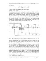
Measures to Obtain or Improve
the Acoustic Protection
Structure-borne sound
In order to avoid structure-born sound, contact to the masonry
must be avoided:
• the pipe system should not touch walls or ceilings at any
point. Wall or ceiling penetrations should be closed with
non-combustible mineral wool. Shafts should be stuffed
with mineral wool or be lined with noise-absorbing material.
• fixing brackets should be rubber-lined. When closing the
brackets, the rubber lining should not be pressed too tightly
to the pipe. Plastic spacers between the two bracket halves
may help reduce the pressure.
• in very sensitive areas, it may be advisable to use special
noise-damping fixing brackets; e.g. acoustic dampeners that
are fixed to the thread rod of the bracket.
• in vertical pipes, down pipe supports should not be spaced too
far apart in order to avoid too high pressure on the rubber ring.
Airborne sound
The water flow in the pipes must be eased to reduce flow noises:
• the transition from a down pipe of a height of 10 m or more to
a horizontal pipe should be carried out using a bend with
steadying distance
• sideways offsets of a down pipe must also be carried out
with bends with steadying distance, both above and below
• the connection of a down pipe to a horizontal line must be
carried out with 45° branch and 45° bend
• the connection of a horizontal pipe to a down pipe should
be carried out with 88° branch with 45° access angle.
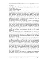
Tests and Certificates
As certified by certificate No. P-BA 443/1995 of Fraunhofer insti-
tute, Düker cast iron pipes reached a noise level of 19.9 dB(A) in
the room diagonally across from the pipeline. This was measured
with walls of 220 kg/m² and a water volume of 4.0 l/s.
Fraunhofer Test Assembly
test water volume:
a) 0.5 l/s
b) 1.0 l/s
c) 2.0 l/s
d) 4.0 l/s
lower storey
test results :
a) 6.1 dB(A)
b) 9.7 dB(A)
c) 14.5 dB(A)
d) 19.9 dB(A)
basement
test results :
a) 12.1 dB(A )
b) 16.3 dB(A )
c) 20.1 dB(A )
d) 24.9 dB(A )
receptacle
upper storey
14
Material Properties
15
MATERIAL PROPERTIES
resistance exceeding EN 877requirements of EN 877
Material Characteristics
DENSITY:
Approx. 7.2 kg/dm
3
(71.5 KN/m
3
)
MINIMUM TENSILE STRENGTH:
150 MPa for fittings,
200 MPa for pipes
COMPRESSIVE STRENGTH:
Approx. 3 to 4 times the value of
the minimum tensile strength
SHEARING STRENGTH:
1.1 to 1.6 times the value of the
minimum tensile strength
CRUSHING STRENGTH:
350 MPa (for DN < 250)
or 332 MPa (for DN ≥ 250)
POISSON’S NUMBER: 0.3
COEFFICIENT OF LENGTH
EXPANSION:
0.0105 mm/mK
(between 0° and 100 °C)
THERMAL CONDUCTION COEFFICIENT:
50 - 60 W/mK (at 20°C)
MODULUS OF ELASTICITY:
8 x 10
4
to 12 x 104 N/mm
2
CHEMICAL RESISTANCE:
For use with domestic effluents
within a range of ph 2 - ph 12.
Well above the values required
by EN 877.
For non-domestic applications and
for aggressive waste water we
recommend to consult with Düker
and where applicable to use a different
coating such as Düker MLK-protec.
Hubless Cast Iron Drainage Pipes
by Düker
Since 1913 Düker has been offering all material-related advan-
tages which are proven in cast iron - high strength of material
and resistance to wear, excellent temperature and corrosion
resistance, considerable sound damping ability and above all
the non-combustibility - in cast iron drainage pipes.
Düker revolutionised the market in terms of building and laying
techniques by developing cast iron spigot end drainage pipes
which were approved for Düker for the first time in 1967 with the
test certificate PA-I 1609. Just as before, the SML drainage pipe
system today distinguishes itself by reliability and quality. For
use in high-quality building drainage and on the basis of EN 877.
Interior Coating Resistance of Düker SML Pipes
for Domestic Applications with Discontinuous Use
EN 877
up to 23 °C up to 50 °C up to 80 °C
pH 0
pH 1 (except organic acids)
pH 2 (except organic acids)
lime-dissolving substancesl
cleaning products
detergents
disinfectants
stain removers
oxidants
water, salts
drain clearing products
solvents
pH 12
pH 13
pH 14
01 SML DELIVERY PROGRAMME
16
17
01 SML DELIVERY PROGRAMME
nominal
diameter exterior diameter wall thickness insertion lengths pipe weight surface
pipes and fittings sealing zone empty ca. m
2
DN kg item no.
40 10,5 660744
50 15,9 660004
70* 18,3 660094
80 20,6 235145
100 25,4 660184
125 33,3 660274
150 42,1 660364
200 72,7 660454
250 96,3 660654
300 135,3 660664
400 192,2 660604
500**
600**
* obsolete model, ** on request (see MLB programme)
L = 3000 mm
SML pipe DIN 19522
SML Pipes
40 48 +2/-1 3,0 2,5 30 3,5 0,15
50 58 +2/-1 3,5 3,0 30 5,3 0,18
70* +2/-1 3,5 3,0 35 5,9 0,25
80
1)
83 +2/-1 3,5 3,0 35 6,9 0,26
100 110 +2/-1 3,5 3,0 40 8,5 0,35
125 135 +2/-2 4,0 3,5 45 11,1 0,42
150 160 +2/-2 4,0 3,5 50 14,0 0,50
200 210 +2,5/-2,5 5,0 4,0 60 24,2 0,65
250 274 +2,5/-2,5 5,5 4,5 70 32,1 0,85
300 326 +2,5/-2,5 6,0 5,0 80 45,1 1,02
400 429 +2/-3 6,3 5,0 80 64,1 1,35
600**
All dimensions in mm
* obsolete model, ** on request (see MLB programm)
1)
) The nominal diameter DN 80 with a minimum interior diameter of 75 mm corresponds to
DN 80 as per EN 12056-2 as well as to DN 75 as per EN 877 (product standard)
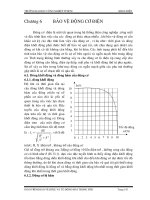
Construction dimensions:
Pipe diameter
Wall thicknesses
Insertion lengths (sealing zone)
Pipe weights
Surface
Verbindung
t
Formstück
DE
e
Rohr
L
Ø D
x
8
L
L
A
D
1
D
2
13
*
c
B
A
SML pipes and SML fittings (EN 877 and DIN 19 522)
DN DE tolerance nominal minimum t ca. kg/m per m
coupling
t
fitting
DE
e
pipe
L
ØD
x
8
L
L
A
D
1
D
2
13
*
c
B
A
500**
78
18
SML DELIVERY PROGRAMME 01
Verbindung
t
Formstück
DE
e
Rohr
L
Ø D
x
8
L
L
A
D
1
D
2
13
*
c
B
A
Verbindung
t
Formstück
DE
e
Rohr
L
Ø
D
x
8
L
L
A
D
1
D
2
13
*
c
B
A
SML reducer DIN 19522
DN A L kg item no.
50 x 40 5 65 0,5 662484
70 x 50* 10 75 0,5 662504
80 x 50 12,5 80 0,7 235159
100 x 50 25 80 0,9 662514
100 x 70* 16 85 0,9 662524
100 x 80 13,5 90 1,1 235161
125 x 50 38,5 85 1,4 662534
125 x 70* 28,5 90 1,5 662544
125 x 80 26 95 1,7 235162
125 x 100 12,5 95 1,5 662554
150 x 50 51 95 2,0 662564
150 x 70* 41 100 2,0 662574
150 x 80 37,5 100 2,3 235417
150 x 100 25 105 2,2 662584
150 x 125 12,5 110 2,2 662594
200 x 100 50 115 4,1 662604
200 x 125 37,5 120 4,1 662614
200 x 150 25 125 4,3 662624
250 x 150 57 140 6,8 662634
250 x 200 32 145 7,0 662644
300 x 150 83 150 10,7 662494
300 x 200 58 160 11,4 662714
300 x 250 26 170 12,4 662724
400 x 300** 51,5 180 15,0 662444
* obsolete model, ** on request
SML down pipe support DIN 19522
DN D X L kg item no.
support without support without support incl.
bearing ring bearing ring bearing ring
50 87 96 200 1,3 661544 223825
70* 106 96 200 1,6 661554 223830
80 114 96 200 1,8 235164 235343
100 145 96 200 2,3 661564 223834
125 170 96 200 3,0 661574 223839
150 195 96 200 4,0 661584 223841
200 245 96 200 6,0 661594 223843
250 340 146 300 19,5 100242 230053
300 390 146 300 25,5 100244 230054
* obsolete model
Verbindung
t
Formstück
DE
e
Rohr
L
Ø D
x
8
L
L
A
D
1
D
2
13
*
c
B
A
Bearing rings with rubber
for down pipe supports
Reducers
SML Down Pipe Supports
DN D
2
D
1
A B C * kg item no.
50 61 93 193 148 25 33 0,8 666314
70* 81,5 114 214 166 26 33 1,0 666324
80 86,5 120 214 166 31 32 1,0 235344
100 115 147 250 202 28 33 1,3 666334
125 138 171 275 225,5 28 33 1,5 666344
150 163 199 301 253,5 30 33 2,0 666354
200 215 250 360 310,5 30 36 3,0 666374
250 280 344 442 392 34 40 5,6 227152
300 332 393 495 445 39 40 7,4 227153
* obsolete model
Installation Example with
Console (available
in the trade)
Bearing Rings
19
01 SML DELIVERY PROGRAMME
SML bend DIN 19522
DN X kg item no.
40 70 0,5 661414
50 75 0,7 661054
70* 90 1,1 661114
80 95 1,4 235150
100 110 2,1 661174
125 125 3,2 661234
150 145 4,9 661294
200 180 8,8 662784
250** 225 13,8 233621
300** 260 28,0 233622
SML Bends 88°
x
x
88
°
x
x
68
°
45
°
x
x
30
°
x
x
15
°
x
x
SML Bends 68°
50 65 0,7 661034
70* 75 1,1 661094
80 80 1,2 235149
100 90 1,9 661154
125 105 2,9 661214
150 120 4,9 661274
200 145 7,7 661334
S DN X kg item no.
x
x
88
°
x
x
68
°
45
°
x
x
30
°
x
x
15
°
x
x
SML Bends 45°
40 50 0,4 661404
50 50 0,5 661024
70* 60 0,9 661084
80 60 1,0 235148
100 70 1,6 661144
125 80 2,3 661204
150 90 3,5 661264
200 110 6,5 661324
250 130 10,3 661374
300 155 17,3 661394
400** 257 36,0 661284
S DN X kg item no.
x
x
88
°
x
x
68
°
45
°
x
x
30
°
x
x
15
°
x
x
SML Bends 30°
50 45 0,5 661014
70* 50 0,7 661074
80 60 0,8 235147
100 60 1,3 661134
125 70 2,0 661194
150 80 3,0 661254
200 95 5,4 661314
250 110 9,7 661364
300 130 15,5 661384
DN X kg item no.
x
x
88
°
x
x
68
°
45
°
x
x
30
°
x
x
15
°
x
x
SML Bends 15°
50 40 0,4 661004
70* 45 0,6 661064
80 50 0,7 235146
100 50 1,0 661124
125 60 1,7 661184
150 65 2,5 661244
200 80 4,6 661304
* obsolete model, ** on request
DN X kg item no.
x
x
88
°
x
x
68
°
45
°
x
x
30
°
x
x
15
°
x
x
20
K
X1
X2
88
°
K
X1
X
2
45
°
44°
44°
X
2
X3
X
3
X1
X
1
X1
X
1
44°
44°
X
2
X3
X
3
SML bend with long spigot 88° DIN 19522
DN X
1
X
2
K** kg item no.
70* 250 90 160 2,8 662064
80 250 95 155 2,6 236348
100 250 110 140 4,6 662084
* obsolete model, ** dimension for maximum cut-back
SML bend with long spigot 45° DIN 19522
DN X
1
X
2
K** kg item no.
70* 250 60 190 2,6 662054
80 250 60 190 2,5 236347
100 250 70 180 4,2 662074
* obsolete model, ** dimension for maximum cut-back
SML double bend 88° DIN 19522
DN X
1
X
2
X
3
kg item no.
50 50 100 121 1,2 661484
70* 60 120 145 1,8 661494
80 60 120 145 2,0 235151
100 70 140 170 3,2 661504
125 80 160 195 4,6 661514
150 90 180 219 7,0 661524
* obsolete model
SML Bends 88°
with 250 mm spigot
SML Bends 45°
with 250 mm spigot
SML Double Bends 88°
from 2 bends 44°
K
X1
X2
88
°
K
X1
X
2
45
°
44°
44°
X
2
X
3
X
3
X1
X
1
X1
X
1
44°
44°
X
2
X3
X
3
K
X1
X2
88
°
K
X1
X
2
45
°
44°
44°
X
2
X3
X
3
X1
X
1
X1
X
1
44°
44°
X
2
X3
X
3
As per German DIN 1986, turns of base and collecting pipes may only be carried out with pre-
manufactured bends. Each single bend may only have 45°.
Normally, two bends 45° must be installed for this case. With the double bend, one coupling is no
longer necessary and installation is simplified. Furthermore, this fitting offers the possibility of fixing
a bracket in the middle.
The bend is also suitable for transition from a down pipe to a horizontal pipe and vice versa.
SML DELIVERY PROGRAMME 01
SML Bends 135°
for ventilation
L
x
L
x
K
K
r
67
45
°
L
130
xx
x
15 °
x
A
L
30°
x
x
A
L
45°
x
x
A
L
L
65
xx
200
L
x
x
SML bend 135° for ventilation DIN 19522
DN X K** L kg item no.
100 312 100 150 5,0 662774
** dimensions for maximum cut-back
(see installation hint on page 24)
SML flow-calming bend 88° DIN 19522
DN X
1
X
2
X
3
kg item no.
70* 60 301 273 3,2 662734
80 60 301 273 3,4 236349
100 70 312 291 4,8 662744
125 80 322 308 6,8 662754
150 90 334 326 9,6 662764
* obsolete model
SML Flow-calming Bends 88°
with 250 mm steadying distance for
adapting down pipes to draft pipes
K
X1
X2
88
°
K
X1
X
2
45
°
44°
44°
X
2
X
3
X
3
X1
X
1
X1
X
1
44°
44°
X
2
X3
X
3
German DIN 1986 says that for down pipes running through four to eight storeys or with a length of
10 to 22 m, special arrangements must be taken. Supply and running bend of a draft pipe are to be
resolved with a separator of 250 mm length.
01 SML DELIVERY PROGRAMME
SML long radius bend 88°
DN X1 X2 R kg kg item no. item no.
with access without access with access without access
100 230 230 150 5,5 5,1 100262 235125
150 245 245 150 - 7,8 - 235126
SML short radius access bend 88°
DN X kg item no.
100 110 3,3 100268
150 145 6,1 232741
x
x
SML bend with vent 88°
DN X kg item no.
100 x 50 91 2,2 232445
SML bend with high heel 88°
DN A kg item no.
100 x 50 195 58 2,4 235529
X
X
88°
88°
X
SML Short Radius Access
Bends 88°
SML Long Radius Bends 88°
with/without access
SML Bends 88°
with vent
SML Bends 88°
with high heel
21
X
22
SML DELIVERY PROGRAMME 01
DN X A L
50 45 48 172
70 60 60 224
80 60 60 224
100 60 63 228
125 70 73 266
150 80 83 303
200 95 98 359
250 110 113 415
300 130 133 489
SML S-Bends
made of 2 SML bends 30°
L
x
L
x
K
K
r
67
45
°
L
130
xx
x
15 °
x
A
L
30°
x
x
A
L
45°
x
x
A
L
L
65
xx
200
L
x
x
Fitting/bend combinations
DN X A L
50 40 27 162
70 50 26 197
80 50 26 197
100 50 27 201
125 60 32 241
150 65 35 260
200 80 43 319
SML S-Bends
made of 2 SML bends 15°
L
x
L
x
K
K
r
67
45
°
L
130
xx
x
15 °
x
A
L
30°
x
x
A
L
45°
x
x
A
L
L
65
xx
200
L
x
x
SML S-bend 65 mm DIN 19522
DN X L kg item no.
100 70 340 4,5 662884
SML S-Bends
offset = 200 mm
L
x
L
x
K
K
r
67
45
°
L
130
xx
x
15 °
x
A
L
30°
x
x
A
L
45°
x
x
A
L
L
65
xx
200
L
x
x
SML S-bend 65 mm DIN 19522
DN X L kg item no.
100 70 270 3,5 662874
SML S-Bends
offset = 130 mm
L
x
L
x
K
K
r
67
45
°
L
130
xx
x
15 °
x
A
L
30°
x
x
A
L
45°
x
x
A
L
L
65
xx
200
L
x
x
SML S-Bends
offset = 65 mm
L
x
L
x
K
K
r
67
45
°
L
130
xx
x
15 °
x
A
L
30°
x
x
A
L
45°
x
x
A
L
L
65
xx
200
L
x
x
SML S-bend 65 mm DIN 19522
DN X L kg item no.
100 70 205 2,5 662864
23
01 SML DELIVERY PROGRAMME
DN X A L
50 50 74 174
70 60 85 205
80 60 85 205
100 70 103 243
125 80 117 277
150 90 131 311
200 110 159 379
250 130 187 447
300 155 223 533
SML S-Bends
made of 2 SML bends 45°
L
x
L
x
K
K
r
67
45
°
L
130
xx
x
15 °
x
A
L
30°
x
x
A
L
45°
x
x
A
L
L
65
xx
200
L
x
x
Bend combinations
SML S-Bends
made of 2 SML bends 45°
with 250 mm spigots
2 x 45°
K
A
L
2 x 45°
K
A
L
DN A max. A min. L max. L min. K*
70 223 88 533 398 190
80 223 88 533 398 190
100 230 103 550 423 180
* Dimension for maximum cut-back
Bends with 250 mm spigots can be reduced by the K-dimension at the most. This allows optimum
adaptation of the pipes to the solidium. A reducing quotient of 1:1.5 can be used in site practice for
45° bends. This means: for a decrease of the distance dimensions A and L by 1 cm, the diagonally
running longer spigot is to be shortened by 1.5 cm. In the above chart, 5 mm were added for the
distance of the coupling. Because of the simple calculation method we dispense with the illustration
of the three further combination possibilities of these bends (long spigots with long, short with
short or one long spigot above).
2 x 45°
K
A
L
2 x 45°
K
A
L
DN A max. A min. L max. L min. K*
70 283 148 473 338 190
80 283 148 473 338 190
100 300 173 480 353 180
* Dimension for maximum cut-back
Due to cut-back possibilities, even the deviation made of 2 SML bends 45° with 250 mm spigots
shown here allows good adaptation of the pipes to the solidium. Reducing quotient as in the previ-
ous example 1:1.5. This also is only one example out of 4 different combination possibilities.
These combinations equal a hydraulically favourable and installation-friendly pipe direction with all
deviations: vertical-horizontal, horizontal-vertical and horizontal-horizontal. The overall lengths ”L”
can also be lessened by cutting back the long supplying or draining spigots.
Deviation
made of 2 SML bends 45°
with 250 mm spigots
Bend combinations
24
K
branch 45°
L
bend 45°
B
A
Combinations of SML bends and SML branches (bend with 250 mm spigot)
Combination Examples
branch 45° - bend 45°
branch 45° bend 45° A A B B L K*
DN DN max. min. max. min.
70 x 70 70 283 149 398 264 200 190
80 x 80 80 293 159 418 284 225 190
100 x 70 70 301 166 406 271 215 190
100 x 80 80 304 170 419 285 230 190
100 x 100 100 315 187 455 327 260 180
125 x 70 70 311 177 411 277 225 190
125 x 80 80 322 187 422 287 240 190
125 x 100 100 329 202 459 332 270 180
* Dimension for maximum cut-back
The reducing quotient 1:1.5 in site praxis is also permitted here. When decreasing the distances A
and B by 1 cm (both change at the same time), the bend must be cut back by 1.5 cm.
SML DELIVERY PROGRAMME 01
Combination Examples
branch 88° - bend 88°
L
K
branch 88°
bend 88°
B
A
L
K
Abzweig 88°
Bogen 88°
B
A
L
X2
X3
45
°
X1
88
°
L
x
L
x
K
K
r
67
45
°
45
°
max./min.
L
X2
X
3
X1
Combinations of SML branches 45° and SML bends 135° for bypasses
branch 88° bend 88° A A B L K*
DN DN max. min.
70 x 70 70 350 190 187 180 160
80 x 80 80 350 195 197 180 155
100 x 80 80 365 210 207 190 155
100 x 100 100 370 230 225 220 140
125 x 80 80 380 225 213 205 155
125 x 100 100 385 245 235 235 140
* Dimension for maximum cut-back
DN max. min.
100 x 100 370 300
125 x 100 380 310
150 x 100 395 325
200 x 100 410 340
branch 45°
L
bend 45°
B
A
K
In this case, the reducing quotient is 1:1. The distance A changes identically to the reduction of
the bend. Dimensional tolerances for distance B which theoretically result from the descent are
unimportant for installation practice.
German DIN 1986-100 requires bypass lines for ventilation purposes in the following cases:
• down pipes over 10 m height with a sideways offset of more than 2m
• down pipes over 22 m height at any offsets and at the transition into a horizontal line
The upper connection between the bypass and the downpipe is executed with a 135° bend.
Combinations of SML bends and SML branches
(bend with 250 mm spigot)
branch 45° bend 45° A A B B L K*
DN DN max. min. max. min.
70 x70 70 343 209 338 204 200 190
80 x 80 80 353 219 358 224 225 190
100 x 70 70 361 226 346 212 215 190
100 x 80 80 364 230 359 225 230 190
100 x 100 100 385 257 385 257 260 180
125 x 70 70 371 237 351 217 225 190
125 x 80 80 382 247 362 227 240 190
125 x 100 100 399 272 389 262 270 180
Combination Examples
branch 45° - bend 45°
Combination Examples
branch 45° - bend 135°
25
01 SML DELIVERY PROGRAMME
SML double branch 45°
DN X1 X2 X3 kg item no.
100 x 100 260 190 190 4,0 100260
125 x 100 280 220 220 6,5 237737
150 x 100 280 225 225 8,4 661444
45°
X
1
X
2
X
3
45
°
L
X2
X
3
X1
Abzweig 45°
L
Bogen 45
°
B
A
K
K
Abzweig 45°
L
Bogen 45
°
B
A
SML single branch 45° DIN 19522
DN X
1
X
2
X
3
L kg
item no.
40 x 40 45 115 115 160 1,0 664544
50 x 40 45 115 115 160 1,1 664554
50 x 50 50 (45) 135 (115) 135 (115) 185 (160) 1,4 (1,2) 663004
70 x 50* 40 150 (130) 150 (130) 190 (170) 1,6 663034
80 x 50 50 140 140 190 1,8 235152
70 x 70* 55 160 (145) 160 (145) 215 (200) 2,3 (2,1) 663064
80 x 80 65 160 160 225 2,4 235154
100 x 50 35 (30) 165 (150) 165 (150) 200 (180) 2,5 (2,3) 663094
100 x 70* 50 (45) 185 (170) 185 (170) 235 (215) 3,3 (3,0) 663124
100 x 80 55 175 175 230 3,3 235156
100 x 100 70 205 (190) 205 (190) 275 (260) 4,2 (3,8) 663154
125 x 50 20 185 (170) 185 (170) 205 (190) 3,4 (3,2) 663184
125 x 70* 40 200 (185) 200 (185) 240 (225) 4,3 (4,0) 663214
125 x 80 40 200 200 240 4,4 235342
125 x 100 60 220 (210) 220 (210) 280 (270) 5,2 (5,0) 663244
125 x 125 80 (75) 240 (230) 240 (230) 320 (305) 6,4 (6,1) 663274
150 x 70* 30 215 (205) 215 (205) 245 (235) 5,6 (5,3) 663334
150 x 80 30 215 215 245 5,9 235415
150 x 100 55 240 (225) 240 (225) 295 (280) 6,8 (6,5) 663364
150 x 125 70 255 (245) 255 (245) 325 (315) 8,0 (7,7) 663394
150 x 150 90 265 265 355 9,2 663424
200 x 70* 15 240 (235) 240 (235) 255 (250) 8,1 (8,0) 663484
200 x 80 15 240 240 255 8,5 235416
200 x 100 40 265 (260) 265 (260) 305 (300) 10,0 (9,8) 663514
200 x 125 55 280 280 335 11,9 663544
200 x 150 75 300 300 375 13,3 663574
200 x 200 115 340 340 455 17,2 663604
250 x 100 15 310 (305) 310 (305) 325 (320) 15,4 663634
250 x 125 35 335 (330) 335 (330) 370 (365) 17,7 664504
250 x 150 55 350 350 405 20,2 664514
250 x 200 90 385 (380) 385 (380) 475 (470) 25,1 (24,8) 663644
250 x 250 130 430 430 560 31,5 663654
300 x 100 5 345 345 350 22,0 663664
300 x 125 15 360 360 375 23,9 664524
300 x 150 35 380 380 415 26,9 664534
300 x 200 70 415 440 485 34,0 664444
300 x 250 115 465 465 580 42,1 663674
300 x 300 155 505 505 660 50,1 663684
400 x 300** 105 555 565 660 60,0 663694
* obsolete model, ** on request
Due to the appearance of the
European standard for SML pipes
and fittings EN 877, the new version
of German DIN 19522 also had to be
changed regarding dimensions and
measures of SML-fittings (values in
brackets=old standard version)
SML Branches 45°
SML Double Branches 45°
Düker produces these items ex-
clusively as per the latest version
of DIN 19522. Due to possible
stocks of the old standard version
please check the actual dimensions
of delivered fittings when pre-
manufacturing or preinstalling.