Controlling a powerflex drive on EtherNetIP with explict messages
Bạn đang xem bản rút gọn của tài liệu. Xem và tải ngay bản đầy đủ của tài liệu tại đây (265.36 KB, 5 trang )
Overall Description
This application note details controlling a PowerFlex40 drive on EtherNet/IP using explicit messages, with
a MicroLogix 1100 PLC being used as the controller. This application note can also be used with the
other PowerFlex 4 class drives with 22-COMM-E, and PowerFlex 7 class drives with 20-COMM-E, and
1305 / 1336 Scanport drives with 1203-EN1. Additionally this application note can be used with SLC
5/05E and PLC5 controllers.
Background and Limitations
Controlling I/O with explicit messages is relatively complex compared to normal implicit I/O control.
ControlLogix / CompactLogix PLC’s with EtherNet/IP provides the easiest and most integrated form of
implicit I/O control for a PowerFlex drive. RSLogix5000 v16.x programming software for ControlLogix /
CompactLogix contains integrated profiles for PowerFlex drives that with a few clicks of the mouse create
all control tags automatically and an implicit connection at the specified Requested Packet Interval to
control the drive. This connection is monitored at both ends to ensure that the PLC and drive are
communicating. A watchdog will cause a drive fault if the drive doesn’t respond in the order of 100mSecs.
Therefore using ControlLogix / CompactLogix, is by far the much preferred method of controlling drives
on EtherNet/IP.
If you are not using these PLC’s, then PowerFlex drives on EtherNet/IP can be controlled with explicit
messages using ML1100, SLC and PLC5, with the following limitations:
•
An explicit message is a much slower form of control and non deterministic. This means that you
cannot guarantee how long the drive will take to start up / stop when the command is given.
Therefore all equipment used in this manner, should be subject to a risk assessment, taking into
account the mechanical and electrical implementation.
•
A time-out value (in seconds) in the drive will issue a drive fault if a message is not received from
the PLC within the specified time. However the PLC has no way of detecting a loss of comms to
the drive, until the next cycle of explicit messages. This is another factor in the risk assessment.
•
Any additional drives to be controlled, will require additional explicit messages for control which
need to be carefully sequenced. Most PLC’s (refer to PLC user manuals) have small
communication queues, which need to be carefully managed if messages are not to be lost.
•
Each PLC has a limited number of communication connections (refer to PLC user manuals for
max connections), which will limit the number of drives that can be connected.
•
Unlike a ControlLogix / CompactLogix solution, programming a controller using RSLogix5 /
RSLogix500 software with explicit messages is a lot more difficult, and produces a far more
complex program.
Distribution:
x Open
Rockwell Offices
Drives Team
Related to:
x
Inverter Use
Options Use
Application Experience
_________________(Name) only
Page 1 of 5
Generated by
Date
Revision
D.J.Withenshaw
19/05/2008
A
Description
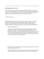
Controlling a drive with explicit messages involves the use of PCCC emulated block transfer using NFiles. ( Refer to EtherNet/IP PCCC Objects in the 22-COMM-E user manual)
Firstly we need to send a time-out value to the drive (in seconds), before sending any control data. The
N42:3 value normally defaults to 0, and so needs a non 0 value before it accepts any valid control data.
The screenshot above details a value of 5 (secs) in N20:0 which will need to be sent to the drive. The
following MSG instruction is used:
The format of the message is as below:
Distribution:
x Open
Rockwell Offices
Drives Team
Related to:
x Inverter Use
Options Use
Application Experience
_________________(Name) only
Page 2 of 5
Generated by
Date
Revision
D.J.Withenshaw
19/05/2008
A
N.B. The time-out value message above is being sent continuosly. In reality it would only need sending
once whilst the drive is powered up.
Now we can send the Logic Control and reference words. The user manual details these starting from
N41:0. The user program (detailed later in this application note) writes the control data for the Logic
Control word at N20:20 and the Speed Reference at N20:22. Therefore the explicit messages is:
Additionally we can read the Logic Status and Feedback words. The user manual details these starting
from N41:0. The user program (detailed later in this application note) reads the status data for the Status
word and locates it at N20:1 and the Speed Feedback at N20:3. Therefore the explicit messages is:
Distribution:
x Open
Rockwell Offices
Drives Team
Related to:
x Inverter Use
Options Use
Application Experience
_________________(Name) only
Page 3 of 5
Generated by
Date
Revision
D.J.Withenshaw
19/05/2008
A
Here is an example of the Logic program for the Logic Status / Feedback:
Distribution:
x Open
Rockwell Offices
Drives Team
Related to:
x Inverter Use
Options Use
Application Experience
_________________(Name) only
Page 4 of 5
Generated by
Date
Revision
D.J.Withenshaw
19/05/2008
A
Here is an example of the Logic program for the Logic Command / Reference:
Distribution:
x Open
Rockwell Offices
Drives Team
Related to:
x Inverter Use
Options Use
Application Experience
_________________(Name) only
Page 5 of 5
Generated by
Date
Revision
D.J.Withenshaw
19/05/2008
A