Bài giảng kỹ thuật vi xử lý - Chương 5: Thiết kế các cổng I/O pot
Bạn đang xem bản rút gọn của tài liệu. Xem và tải ngay bản đầy đủ của tài liệu tại đây (239.92 KB, 33 trang )
Bài gi ng K thu t Vi x lý
Ngành i n t -Vi n thông
i h c Bách khoa à N ng
c a H Vi t Vi t, Khoa TVT
Tài li u tham kh o
[1] K thu t vi x lý, Văn Th Minh, NXB Giáo d c, 1997
[2] K thu t vi x lý và L p trình Assembly cho h vi x
lý,
Xuân Ti n, NXB Khoa h c & k thu t, 2001
Chương 5
Thi t k các c ng I/O
5.1 I/O ư c phân vùng nh và I/O tách bi t
- I/O ư c phân vùng nh (Memory Mapped I/O)
- I/O tách bi t (Isolated I/O)
5.2 Các chip MSI dùng làm c ng I/O
- C ng ra
- C ng vào
5.3 Chip 8255
- Sơ
chân, Sơ
kh i ch c năng
- Các mode ho t ng
- Gi i mã a ch
- L p trình cho 8255
5.1 C n phân bi t 2 ki u thi t k
• I/O ư c phân vùng nh (Memory mapped I/O):
- 1 c ng ư c xem như m t ô nh
- 1 c ng có a ch 20-bit
- ư c truy c p khi IO/M = 0
- không c n m ch gi i mã a ch riêng
• I/O tách bi t (isolated I/O)
- 1 c ng ư c xem úng là 1 c ng
- 1 c ng có a ch 16-bit, 12-bit, 8-bit
- ư c truy c p khi IO/M = 1
- c n m ch gi i mã a ch I/O riêng
5.2 Các chip MSI thư ng dùng làm c ng I/O
•
•
•
•
•
•
74LS373
74LS374
74LS244
74LS245
Khi s lư ng c ng ít và c
nh
Cách m c m ch s quy t nh cho chip là
c ng ra hay c ng vào và a ch c a nó
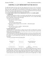
S d ng 74LS245 làm c ng ra
A19
A18
:
A0
D7
D6
D5
D4
D3
D2
8088
Minimum
Mode
D1
D0
A0
A1
A2
A3
B0
B1
B2
B3
A4
B4
74LS245 B5
A5
A6
B6
A7
B7
E
IOR
IOW
A A A A A A A A A A A A A A A A IOW
1111119876543210
543210
DIR
5V
:
mov al, 55
mov dx, F000
out dx, al
:
S d ng 74LS373 làm c ng ra
A19
A18
:
A0
D3
D0
D1
D2
D3
D4
D2
D1
D0
D5
D6
D7
D7
D6
D5
D4
8088
Minimum
Mode
Q0
Q1
Q2
Q3
Q4
74LS373 Q5
LE
IOR
IOW
A A A A A A A A A A A A A A A A IOW
1111119876543210
543210
Q6
Q7
OE
:
mov al, 55
mov dx, F000
out dx, al
:
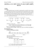
S d ng 74LS245 làm c ng vào
5V
A19
A18
:
A0
D3
A0
A1
A2
A3
A4
D2
D1
D0
A5
A6
A7
D7
D6
D5
D4
8088
Minimum
Mode
B0
B1
B2
B3
B4
74LS245 B5
E
IOR
IOW
B6
B7
DIR
:
mov dx, F000
in al, dx
:
A A A A A A A A A A A A A A A A IOR
1111119876543210
543210
C ng ra
C ng vào
5.3 Chip LSI thư ng dùng làm c ng I/O
• PPI 8255
• Khi s lư ng c ng I/O nhi u và khơng c
nh
• Cách m c m ch s quy t nh a ch cho
các c ng còn vai trò c a c ng s ư c
quy t nh b i ph n m m
8255 PPI
Sơ
kh i ch c năng c a 8255
Các mode làm vi c
• Mode 0
- PA, PB, PCH (CU) và PCL (CL)
- Có th là Input ho c Output
- Vi c Nh p ho c Xu t d li u là c l p
• Mode 1
- PA, PB
- Có th là Input ho c Output
- Vi c Nh p ho c Xu t d li u là ph thu c vào m t s
bít c a PC (các tín hi u handshaking)
• Mode 2
- PA
- PA v a là Input v a là Output
- Vi c Nh p/Xu t d li u v i PA là ph thu c vào m t s
bít c a PC (các tín hi u handshaking)
Nhóm làm vi c
• Nhóm A: PA và PCH
• Nhóm B: PB và PCL
• nh c u hình làm vi c cho 1 chip 8255:
G i 1 T i u khi n nh c u hình n
thanh ghi i u khi n c a chip ó
• L p/xố m t bit c a PC: G i 1 T i u
khi n L p/Xoá bit n thanh ghi i u khi n
c a chip ó
T
i u khi n
nh c u hình làm vi c cho m t chip 8255
T
i u khi n l p/xoá bit cho m t chip 8255
The 8255 Programmable Peripheral Interface
• Intel has developed several peripheral controller chips designed to support the 80x86
processor family. The intent is to provide a complete I/O interface in one chip.
• 8255 PPI provides three 8 bit input ports in one 40 pin package making it more
economical than 74LS373 and 74LS244
• The chip interfaces directly to the data bus of the processor, allowing its functions to be
programmed; that is in one application a port may appear as an output, but in another,
by reprogramming it as an input. This is in contrast with the 74LS373 and 74LS244
which are hard wired and fixed.
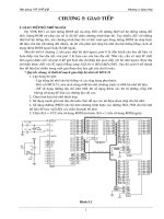
8255 Pins
• PA0 - PA7: input, output, or bidirectional port
• PB0 - PB7: input or output
• PC0 - PC7: This 8 bit port can be all input or output. It can also be split into two parts,
CU (PC4 - PC7) and CL (PC0 - PC3). Each can be used for input and output.
• RD or WR
– IOR and IOW of the system are connected to these two pins
• RESET
• A0, A1, and CS
– CS selects the entire chip whereas A0 and A1 select the specific port (A, B, or C) or
Control Register.
Gi i mã
a ch cho 8255
Mode 0 - Simple input/output
• Simple I/O mode: any of the ports A, B, CL, and CU can be programmed as input or
output.
• Example: Configure port A as input, B as output, and all the bits of port C as output
assuming a base address of 50h
• Control word should be 1001 0000b = 90h
MOV AL, 90h
OUT 53h,AL
IN AL, 50h
OUT 51h, AL
OUT 52h, AL
Mode 1: I/O with Handshaking Capability
• Handshaking refers to the process of communicating back and forth between two
intelligent devices
• Example. Process of communicating with a printer
– a byte of data is presented to the data bus of the printer
– the printer is informed of the presence of a byte of data to be printed by
activating its strobe signal
– whenever the printer receives the data it informs the sender by
activating an output signal called ACK
– the ACK signal initiates the process of providing another byte of data to
the printer
• 8255 in mode 1 is equipped with resources to handle handshaking
signals