On the Control Aspects of Semiactive Suspensions for Automobile Applications doc
Bạn đang xem bản rút gọn của tài liệu. Xem và tải ngay bản đầy đủ của tài liệu tại đây (2.28 MB, 118 trang )
On the Control Aspects of Semiactive Suspensions for
Automobile Applications
by
Emmanuel D. Blanchard
Thesis submitted to the Faculty of the
Virginia Polytechnic Institute and State University
in partial fulfillment of the requirements for the degree of
Master of Science
in
Mechanical Engineering
Approved:
_________________________
Mehdi Ahmadian, Chairman
_______________________ _____________________
Harry H. Robertshaw Donald J. Leo
June 2003
Blacksburg, Virginia
Keywords: Semiactive, Skyhook, Groundhook, Hybrid, Suspensions,
Vehicle Dynamics, H2
On the Control Aspects of Semiactive Suspensions for
Automobile Applications
by
Emmanuel D. Blanchard
Mehdi Ahmadian, Chairman
Mechanical Engineering
Abstract
This analytical study evaluates the response characteristics of a two-degree-of freedom
quarter-car model, using passive and semi-active dampers, along with a seven-degree-of-
freedom full vehicle model. The behaviors of the semi-actively suspended vehicles have
been evaluated using skyhook, groundhook, and hybrid control policies, and compared to
the behaviors of the passively-suspended vehicles. The relationship between vibration
isolation, suspension deflection, and road-holding is studied for the quarter-car model.
Three main performance indices are used as a measure of vibration isolation (which can
be seen as a comfort index), suspension travel requirements, and road-holding quality.
After performing numerical simulations on a seven-degree-of-freedom full vehicle model
in order to confirm the general trends found for the quarter-car model, these three indices
are minimized using
2
H
optimization techniques.
The results of this study indicate that the hybrid control policy yields better comfort than
a passive suspension, without reducing the road-holding quality or increasing the
suspension displacement for typical passenger cars. The results also indicate that for
typical passenger cars, the hybrid control policy results in a better compromise between
comfort, road-holding and suspension travel requirements than the skyhook and
groundhook control policies. Finally, the numerical simulations performed on a seven-
degree-of-freedom full vehicle model indicate that the motion of the quarter-car model is
not only a good approximation of the heave motion of a full-vehicle model, but also of
the pitch and roll motions since both are very similar to the heave motion.
iii
Acknowledgements
I would like to thank my advisor Dr. Mehdi Ahmadian for his guidance and
support throughout my time as a Master’s student in the Mechanical Engineering
Department, as well as his encouragement. Working at the Advanced Vehicle Dynamics
Laboratory was truly a great experience. I would also like to thank Dr. Donald J. Leo and
Dr. Harry H. Robertshaw for serving on my graduate committee. I am also thankful to
the Mechanical Engineering Department for the financial support of a graduate teaching
assistantship. I would also like to thank Ben Poe and Jamie Archual. Working for them
was also a great experience.
I would also like to thank all my current labmates, Fernando Goncalves, Jeong-
Hoi Koo, Mohammad Elahinia, Michael Seigler, Jesse Norris, Christopher Boggs, Akua
Ofori-Boateng, as well as those who have already left Virginia Tech, Paul Patricio, John
Gravatt, Walid El-Aouar, Jiong Wang, and Johann Cairou, for their companionship and
for their help. Each of them has contributed to this work, at least by making the AVDL
such an enjoyable place to work. I am truly grateful for their assistance. I would
especially like to thank Fernando for also having been such a great roommate and such a
great friend to have, as well as for having helped me so much from the beginning to the
end of my time as a Master’s student.
I would also like to thank all the friends I have made here at Virginia Tech for
their companionship and memories. Finally, I would like to thank my family for their
love and support. I would especially like to thank my parents and grandparents for their
love, care, and financial support during my time as a student. Their help has made this
achievement possible.
iv
Contents
1 Introduction 1
1.1 Motivation 1
1.2 Objectives 2
1.3 Approach 2
1.4 Outline 3
2 Background 5
2.1 Overview of Vehicle Suspensions 5
2.2 2DOF Suspension Systems 7
2.3 Control Schemes for a 2DOF System 10
2.3.1 Skyhook Control 10
2.3.2 Groundhook Control 16
2.3.3 Hybrid Control 17
2.3.4 Passive vs. Semiactive Dampers 19
2.4 Actual Passive Representation of Semiactive Suspensions 20
2.5 H
2
optimization method 21
2.6 Literature Review 23
3 Quarter Car Modeling 26
3.1 Model Formulation 26
3.2 Mean Square Responses of Interest 28
3.3 Relationship Between Vibration Isolation, Suspension Deflection, and
Road-Holding …. 33
3.4 Performance of Semiactive Suspensions 44
4 Full Car Modeling 45
4.1 Model Formulation 45
4.2 Vehicle Ride Response to Periodic Road Inputs 50
4.3 Vehicle Ride Response to Discrete Road Inputs… 62
5 H2 Optimization 67
5.1 Model Formulation 67
v
5.2 Definition of the Performance Indices 68
5.3 Optimization for Passive Suspensions 70
5.3.1 Procedure for H
2
Optimization 70
5.3.2 Optimized Performance Indices 73
5.3.3 Effects of Optimizing the Performance Indices 76
5.4 Optimization for Semiactive Suspensions 80
5.4.1 Optimized Performance Indices 80
5.4.2 Effect of Alpha on Performance Indices 86
6 Conclusion and Recommendations 90
6.1 Summary 90
6.2 Recommendations for Future Research 91
Appendix 1: Detailed Expressions of the Mean Square Responses 93
Appendix 2: Equations of Motion for the Full Car Model 97
Appendix 3: System Matrix A and Disturbance Matrix L 100
References 106
Vita 108
vi
List of Figures
2.1 Passive, Active, and Semiactive Suspensions 6
2.2 2DOF Quarter-Car Model 7
2.3 Passive Suspension Transmissibility: (a) Sprung Mass Transmissibility;
(b) Unsprung Mass Transmissibility 9
2.4 Skyhook Damper Configuration 11
2.5 Skyhook Configuration Transmissibility: (a) Sprung Mass Transmissibility;
(b) Unsprung Mass Transmissibility 12
2.6 Semiactive Equivalent Model 13
2.7 Skyhook Control Illustration 15
2.8 Groundhook Damper Configuration 16
2.9 Groundhook Configuration Transmissibility: (a) Sprung Mass
Transmissibility; (b) Unsprung Mass Transmissibility 17
2.10 Hybrid Configuration 18
2.11 Hybrid Configuration Transmissibility: (a) Sprung Mass Transmissibility;
(b) Unsprung Mass Transmissibility 19
2.12 Transmissibility Comparison of Passive and Semiactive Dampers:
(a) Sprung Mass Transmissibility; (b) Unsprung Mass Transmissibility 20
2.13 Actual Passive Representation of Semiactive Suspension
- Hybrid Configuration 21
3.1 Quarter-Car Suspension System: (a) Passive Configuration;
(b) Semiactive Configuration 27
3.2 Effect of Damping on the Vertical Acceleration Response: (a) Passive;
vii
(b) Groundhook; (c) Hybrid; (d) Skyhook 35
3.3 Effect of Damping on Suspension Deflection Response: (a) Passive;
(b) Groundhook; (c) Hybrid; (d) Skyhook 36
3.4 Effect of Damping on Tire Deflection Response: (a) Passive;
(b) Groundhook; (c) Hybrid; (d) Skyhook 37
3.5 Relationship Between RMS Acceleration and RMS Suspension Travel
(Mass Ratio 0.15): (a) Passive; (b) Groundhook; (c) Hybrid; (d) Skyhook 39
3.6 Relationship Between RMS Acceleration and RMS Tire Deflection
(Mass Ratio 0.15): (a) Passive; (b) Groundhook; (c) Hybrid; (d) Skyhook 41
3.7 Relationship Between RMS Tire Deflection and RMS Suspension Travel
(Mass Ratio 0.15): (a) Passive; (b) Groundhook; (c) Hybrid; (d) Skyhook 43
3.8 Comparison Between the Performances of a Passive Suspension and a
Hybrid Semiactive Suspension (Mass Ratio: 0.15; Stiffness Ratio: 10) 44
4.1 Full-Vehicle Diagram 46
4.2 Heave Response to Heave Input of 1 m/s Amplitude Using Quarter Car
Approximation: (a) Vertical Acceleration; (b) Suspension Deflection;
(c) Tire Deflection 54
4.3 Heave Response to Heave Input of 1 m/s Amplitude at Each Corner:
(a) Vertical Acceleration; (b) Suspension Deflection; (c) Tire Deflection 55
4.4 Pitch Response to Pitch Input of 1 m/s Amplitude at Each Corner:
(a) Angular Acceleration; (b) Suspension Deflection; (c) Tire Deflection 57
4.5 Roll Response to Roll Input of 1 m/s Amplitude at Each Corner:
(a) Angular Acceleration; (b) Suspension Deflection; (c) Tire Deflection 58
4.6 Pitch Response to Heave Input of 1 m/s Amplitude at Each Corner:
viii
(a) Angular Acceleration; (b) Suspension Deflection; (c) Tire Deflection 60
4.7 Heave Response to Pitch Input of 1 m/s Amplitude at Each Corner:
(a) Vertical Acceleration; (b) Suspension Deflection; (c) Tire Deflection 61
4.8 Road Profile Used to Compute the Response of the Vehicle 62
4.9 Pitch Response of the Vehicle When Subjected to the “Chuck Hole” Road
Disturbance 63
4.10 Roll Response of the Vehicle When Subjected to the “Chuck Hole” Road
Disturbance 63
4.11 Vertical Acceleration at the Right Front Seat Due to the “Chuck Hole”
Road Disturbance 65
4.12 Deflection of the Right Rear Suspension Due to the “Chuck Hole” Road
Disturbance 66
4.13 Deflection of the Right Rear Tire Due to the “Chuck Hole” Road
Disturbance 66
5.1 Quarter - Car Model: (a) Passive Suspension; (b) Semiactive Suspension 67
5.2 Effect of Damping on the Vertical Acceleration of the Sprung Mass 77
5.3 Effect of Damping on Suspension Displacement 77
5.4 Effect of Damping on Tire Displacement 78
5.5 Effect of Damping on the Comfort Performance Index for the Semiactive
Suspension: (a) Groundhook; (b) Hybrid with
0.5α
=
; (c) Skyhook 83
5.6 Effect of Damping on the Suspension Displacement Index for the
Semiactive Suspension: (a) Groundhook; (b) Hybrid with
0.5α
=
;
(c) Skyhook 84
5.7 Effect of Damping on the Road Holding Quality Index for the Semiactive
Suspension: (a) Groundhook; (b) Hybrid with 0.5α
=
; (c) Skyhook 85
ix
5.8 Effect of Alpha on the Vertical Acceleration of the Sprung Mass 87
5.9 Effect of Alpha on Suspension Displacement 88
5.10 Effect of Alpha on Tire Displacement 88
x
List of Tables
Table 2.1 System Parameters 8
Table 3.1 Model Parameters 33
Table 4.1 Full Vehicle Model Parameters 47
Table 4.2 Full Vehicle Model States and Inputs 48
Table 4.3 Periodic Inputs Used to Simulate the Vehicle Ride Response 52
Table 5.1 Model Parameters 68
Table 5.2 Optimized Performance Indices 74
1
1 Introduction
The purpose of this chapter is to provide the reader with an introduction to the research
conducted throughout the course of this study. First, an overview of vehicle suspensions
is provided and the motivation for the work is presented. The research objectives and
approach to this research are then discussed. Finally, an outline of the remaining chapters
is provided.
1.1 Motivation
A typical vehicle suspension consists of a spring and a damper. The role of the spring is
to support the static weight of the vehicle. The spring is therefore chosen based on the
weight and ride height of the vehicle. The role of the damper is to dissipate energy
transmitted to the vehicle system by road surface irregularities. In a conventional passive
suspension, both components are fixed at the design stage. The choice of the damper is
affected by the classic trade off between vehicle safety and ride comfort. Ride comfort is
linked to the amount of energy transmitted through the suspension. Car passengers are
especially sensitive to the acceleration of the sprung mass of the car. The safety of a
vehicle, as well as the road holding and the stability, is linked to the vertical motion of
the tires (wheel hop). A low suspension damping provides good isolation of the sprung
mass at the cost of large tire displacements, while a high suspension damping provides
poor isolation of the sprung mass but reduced tire displacements. Therefore, a low
damping provides good road holding and stability at the cost of little comfort, while a
high damping results in good comfort at the cost of poor road holding quality. Luxury
cars are usually lightly damped and sports cars are heavily damped.
The need to reduce the effects of this compromise has led to the development of
active and semiactive suspensions. Active suspensions use force actuators. Unlike a
passive damper, which can only dissipate energy, a force actuator can generate a force in
any direction regardless of the relative velocity across it. Using a good control policy, it
2
can reduce the compromise between comfort and stability. However, the complexity and
large power requirements of active suspensions make them too expensive for wide spread
commercial use. Semiactive dampers are capable of changing their damping
characteristics by using a small amount of external power. Semiactive suspensions are
less complex, more reliable, and cheaper than active suspensions. They are becoming
more and more popular for commercial vehicles.
1.2 Objectives
This study focuses on two primary objectives. The first is to analytically evaluate various
control techniques that can be effectively applied to automobile suspensions. The second
objective is to provide a comparison between selected semiactive control techniques and
passive suspensions that are commonly used in vehicles. The semiactive techniques
include the skyhook, groundhook and hybrid control policies. Performance indices need
to be defined in order to evaluate the benefits and the drawbacks of the different control
techniques.
1.3 Approach
The first step in accomplishing the objectives of this research was to develop the vehicle
models used in this research, along with the passive damping and semiactive damping
control models. Two vehicle models are used for this research: a two-degree-of-freedom
“quarter-car” model and a seven-degree-of-freedom full car model. The two models use
passive representations of the semiactive suspension modeling the ideal skyhook,
groundhook, and hybrid configurations. Using a quarter car model provides the
opportunity to compute mean square responses to random road disturbances and define
performance indices that are simple enough to interpret and optimize after developing the
necessary mathematical models. It, therefore, provides a good understanding of how
each model parameter affects the behavior of the vehicle. Numerical simulations as well
as parametric studies have been performed using the quarter car model. However, the
3
pitch and the roll responses can only be studied with a full car model. A numerical model
has been developed to study the full vehicle ride response to both periodic road inputs
and discrete road inputs.
1.4 Outline
Chapter 2 provides the necessary background information to understand skyhook,
groundhook, and hybrid semiactive control of suspension systems before describing the
actual passive representation of semiactive dampers that will be used in this study. It also
contains an introduction to
2
H optimization techniques and a literature search on
semiactive suspensions and policies, as well as
2
H optimization techniques. In Chapter
3, the relationship between vibration isolation, suspension deflection, and road holding
for both passive and semiactive suspensions is studied based on a quarter car model. The
results obtained for the skyhook, the groundhook, and the hybrid semiactive control
policies are compared to the results obtained for a passive suspension. In Chapter 4, a
numerical model of a full vehicle is used to study the pitch and roll motion of the car for
the passive and semiactive configurations. Periodic and discrete road inputs are used.
The heave response is also simulated to confirm the general results found for the
simplified quarter car model used in Chapter 3. It is shown that working on a simplified
quarter-car model gives a good estimation of the behavior of a full-vehicle. Then,
Chapter 5 introduces
2
H
optimization techniques to optimize the vibration isolation, the
suspension deflection, and the road holding for the quarter-car model. Finally, Chapter 6
summarizes the results of the study and provides recommendations for future research.
The main contributions of this research are:
• A parametric study of the relationship between three performance indices for
different semiactive configurations applied to the quarter-car model, and a
comparison with the results obtained for the passive configuration. These three
4
performance indices are used as a measure of the vibration level, the rattlespace
requirement, and road-holding quality.
• The derivation of closed-form solutions minimizing the three performance indices
for a quarter-car model in which all the components except the damper are fixed.
It is performed using
2
H
optimization techniques.
• A numerical simulation of the full vehicle model’s response to periodic heave,
pitch, and roll inputs for different semiactive control policies, as well as a
comparison with the results obtained for a passive suspension. The cross
coupling effects are also computed.
• A numerical simulation of the full vehicle model’s response to a discrete road
input for different semiactive control policies, as well as a comparison with the
results obtained for a passive suspension.
5
2 Background
The purpose of this chapter is to provide the background for the research conducted in
this study. The first part of this chapter will present an overview of vehicle suspensions.
The second part of this chapter will introduce the reader to a two-degree-of-freedom
(2DOF) quarter-car model and the third part will present three different theoretical
semiactive control schemes for the two-degree-of-freedom (2DOF) suspension system.
Following this, the passive representation of semiactive dampers that will be used in this
study is finally presented. Next, the
2
H optimization technique will be introduced. The
chapter will conclude with a literature search on past research done in areas relating to
this work.
2.1 Overview of Vehicle Suspensions
The primary suspension of a vehicle connects the axle and wheel assemblies to the frame
of the vehicle. Typical vehicle primary suspensions consist of springs and dampers. The
role of the springs is to support the static weight of the vehicle. The springs are therefore
chosen based on the weight and ride height of the vehicle and the dampers are the only
variables remaining to specify. The role of the dampers is to dissipate energy transmitted
to the vehicle system by road surface irregularities. Three common types of vehicle
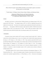
suspension damping are passive, active, and semiactive damping. As illustrated on
Figure 2.1, automobile suspensions can therefore be divided into three categories:
passive, active, and semiactive suspensions.
The characteristics of the dampers used in a passive suspension are fixed. The
choice of the damping coefficient is made considering the classic trade off between ride
comfort and vehicle stability. A low damping coefficient will result in a more
comfortable ride, but will reduce the stability of the vehicle. A vehicle with a lightly
damped suspension will not be able to hold the road as well as one with a highly damped
suspension. When negotiating sharp turns, it becomes a safety issue. A high damping
6
coefficient yields a better road holding ability, but also transfers more energy into the
vehicle body, which is perceived as uncomfortable by the passengers of the vehicle. As
shown on the next part of this chapter with the 2DOF quarter car model, a high damping
coefficient results in good resonance control at the expense of high frequency isolation.
The vehicle stability is improved, but the lack of isolation at high frequencies will result
in a harsher vehicle ride. The need to reduce the effect of this compromise has given rise
to new types of vehicle suspensions.
c
k
Sprung mass
x
s
= fixed
damping
coefficient
Passive suspension
Force
actuator
k
Sprung mass
x
s
Active suspension
c
sa
k
Sprung mass
x
s
= controllable
damping coefficient
varying over time
Semiactive suspension
c
k
Sprung mass
x
s
= fixed
damping
coefficient
Passive suspension
c
k
Sprung mass
x
s
= fixed
damping
coefficient
c
k
Sprung mass
x
s
= fixed
damping
coefficient
Passive suspension
Force
actuator
k
Sprung mass
x
s
Active suspension
Force
actuator
k
Sprung mass
x
s
Active suspension
c
sa
k
Sprung mass
x
s
= controllable
damping coefficient
varying over time
Semiactive suspension
c
sa
k
Sprung mass
x
s
= controllable
damping coefficient
varying over time
c
sa
k
Sprung mass
x
s
= controllable
damping coefficient
varying over time
Semiactive suspension
Figure 2.1: Passive, Active, and Semiactive Suspensions
In an active suspension, the damper is replaced by a force actuator. The
advantage is that the force actuator can generate a force in any direction, regardless of the
relative velocity across it, while a passive damper can only dissipate energy. A good
control scheme can result in a much better compromise between ride comfort and vehicle
stability compared to passive suspensions [1, 2]. Active suspensions can also easily
reduce the pitch and the roll of the vehicle. However, active suspensions have many
disadvantages and are too expensive for wide spread commercial use because of their
complexity and large power requirements. Also, a failure of the force actuator could
make the vehicle very unstable and therefore dangerous to drive.
In semiactive suspensions, the passive dampers are replaced with dampers
capable of changing their damping characteristics. These dampers are called semiactive
dampers. An external power is supplied to them for purposes of changing the damping
level. This damping level is determined by a control algorithm based on the information
7
the controller receives from the sensors. Unlike for active dampers, the direction of the
force exerted by a semiactive damper still depends on the relative velocity across the
damper. But the amount of power required for controlling the damping level of a
semiactive damper is much less than the amount of power required for the operation of an
active suspension. Semiactive suspensions are more expensive than passive suspensions,
but much less expensive than active suspensions and are therefore becoming more and
more popular for commercial vehicles.
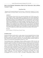
2.2 2DOF Suspension Systems
A typical vehicle primary suspension can be modeled as shown in Figure 2.2. Since the
model represents a single suspension from one of the four corners of the vehicle, this
2DOF system is often referred to as the “quarter-car” model.
K
s
K
t
M
s
M
u
C
s
x
in
x
2
x
x
1
x
K
s
K
t
K
t
M
s
M
u
C
s
C
s
x
in
x
2
xx
2
x
x
1
xx
1
x
Figure 2.2: 2DOF Quarter-Car Model
The parameters used in the simulation of this model, which represent actual
vehicle parameters, are shown in Table 2.1.
8
Table 2.1: System Parameters
Parameter Value
Sprung Body Weight (
S
M)
950 lbs
Unsprung Body Weight (
U
M)
100 lbs
Suspension Stiffness (
S
K)
200 lb/in
Tire Stiffness (
t
K)
1085 lb/in
The input to this model is a displacement input which is representative of a typical
road profile. The input excites the first degree of freedom (the unsprung mass of a
quarter of the vehicle, representing the wheel, tire, and some suspension components)
through a spring element which represents the tire stiffness. The unsprung mass is
connected to the second degree of freedom (the sprung mass, representing the body of the
vehicle) through the primary suspension spring and damper. The transmissibility of the
2DOF system, if all the elements of the quarter-car are passive, is shown in Figure 2.3 for
various damping coefficients. The first plot shows the displacement of the sprung mass
(
2
x ) with respect to the input (
in
x ), while the second plot shows the displacement of the
unsprung mass (
1
x ) with respect to the input (
in
x ).
9
0 2 4 6 8 10 12 14 16 18 20
0
2
4
6
Frequency (Hz)
X2/Xin
0.1
0.3
0.5
0.7
0.9
0 2 4 6 8 10 12 14 16 18 20
0
1
2
3
4
Frequency (Hz)
X1/Xin
0.1
0.3
0.5
0.7
0.9
Damping Ratio (ζ)
Damping Ratio (ζ)
(b)
(a)
0 2 4 6 8 10 12 14 16 18 20
0
2
4
6
Frequency (Hz)
X2/Xin
0.1
0.3
0.5
0.7
0.9
0 2 4 6 8 10 12 14 16 18 20
0
1
2
3
4
Frequency (Hz)
X1/Xin
0.1
0.3
0.5
0.7
0.9
Damping Ratio (ζ)
Damping Ratio (ζ)
(b)
(a)
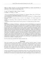
Figure 2.3: Passive Suspension Transmissibility:
(a) Sprung Mass Transmissibility; (b) Unsprung Mass Transmissibility
Notice that at low passive damping, the resonant transmissibility (near
n1
ωω = )
or 1.5 Hz and
n2
ωω =
or 10.5Hz) is relatively large, while the transmissibility at higher
frequencies is quite low. As the damping is increased, the resonant peaks are attenuated,
but isolation is lost both at high frequency and at frequencies between the two natural
frequencies of the system. The lack of isolation between the two natural frequencies is
caused by the increased coupling of the two degrees of freedom with a stiffer damper.
The lack of isolation at higher frequencies will result in a harsher vehicle ride. These
transmissibility plots graphically illustrate the inherent tradeoff between resonance
control and high frequency isolation that is associated with the design of passive vehicle
suspension systems.
10
The equations of motion for the 2DOF system can be written in matrix form as
in
t
1
2
tSS
SS
1
2
SS
SS
1
2
u
s
x
K
0
x
x
KKK
KK
x
x
CC
CC
x
x
M0
0M
=
+−
−
+
−
−
+
&
&
&&
&&
(2.1)
Knowing the physical parameters of the 2DOF system, we can approximate the damping
ratio for each mode. In order to make this approximation, we have to assume that the
system can be decoupled. We will treat the system as two SDOF systems. In order to
present the transmissibility plots as a function of damping ratio rather than damping
coefficient, we can decouple the equations of motion by neglecting the off-diagonal
terms, and then estimate the damping ratio for each mass as
SS
S
S
M K 2
C
ζ =
(2.2)
UtS
S
u
M )K(K 2
C
ζ
+
= (2.3)
While this method of calculating the damping ratio is only valid at low damping, the
intent is not to precisely define the damping ratio, but rather to show the effects of
increased damping on transmissibility.
2.3 Control Schemes for a 2DOF System
This section will introduce the three 2DOF control schemes of interest in this study.
Skyhook, groundhook, and hybrid semiactive control will be presented and compared
with a typical 2DOF passive suspension.
2.3.1 Skyhook Control
As the name implies, the skyhook configuration shown in Figure 2.4 has a damper
connected to some inertial reference in the sky. With the skyhook configuration [3, 4],
the tradeoff between resonance control and high-frequency isolation, common in passive
suspensions, is eliminated [5]. Notice that skyhook control focuses on the sprung mass;
11
as
sky
C increases, the sprung mass motion decreases. This, of course, comes at a cost.
The skyhook configuration excels at isolating the sprung mass from base excitations, at
the expense of increased unsprung mass motion.
K
s
m
1
m
2
x
in
C
sky
M
s
M
u
x
in
K
t
x
1
, v
1
x
2
, v
2
K
s
m
1
m
2
x
in
C
sky
M
s
M
u
x
in
K
t
x
1
, v
1
x
1
, v
1
x
2
, v
2
x
2
, v
2
Figure 2.4: Skyhook Damper Configuration
The transmissibility for this system is shown in Figure 2.5 for different values of
the skyhook-damping coefficient
sky
C
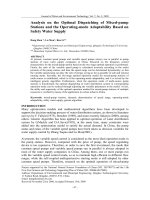
. Notice that as the skyhook damping ratio
increases, the resonant transmissibility near
n1
ω decreases, even to the point of isolation,
but the transmissibility near
n2
ω increases. In essence, this skyhook configuration is
adding more damping to the sprung mass and taking away damping from the unsprung
mass. The skyhook configuration is ideal if the primary goal is isolating the sprung mass
from base excitations [6], even at the expense of excessive unsprung mass motion. An
additional benefit is apparent in the frequency range between the two natural frequencies.
With the skyhook configuration, isolation in this region actually increases with increasing
sky
C.
12
0 2 4 6 8 10 12 14 16 18 20
0
1
2
3
4
Frequency (Hz)
X2/Xin
0.1
0.3
0.5
0.7
0.9
0 2 4 6 8 10 12 14 16 18 20
0
10
20
30
Frequency (Hz)
X1/Xin
0.1
0.3
0.5
0.7
0.9
Damping Ratio (ζ)
Damping Ratio (ζ)
(b)
(a)
0 2 4 6 8 10 12 14 16 18 20
0
1
2
3
4
Frequency (Hz)
X2/Xin
0.1
0.3
0.5
0.7
0.9
0 2 4 6 8 10 12 14 16 18 20
0
10
20
30
Frequency (Hz)
X1/Xin
0.1
0.3
0.5
0.7
0.9
Damping Ratio (ζ)
Damping Ratio (ζ)
(b)
(a)
Figure 2.5: Skyhook Configuration Transmissibility:
(a) Sprung Mass Transmissibility; (b) Unsprung Mass Transmissibility
Because this damper configuration is not possible in realistic automotive
applications, a controllable damper is often used to achieve a similar response to the
system modeled in Figure 2.4. The semiactive damper is commanded such that it acts
like a damper connected to an inertial reference in the sky. Figure 2.6 shows the
semiactive equivalent model with the use of a semiactive damper.
13
M
u
x
2
, v
2
x
in
K
t
M
s
K
s
x
1
, v
1
sa
C
M
u
x
2
, v
2
x
2
, v
2
x
in
K
t
M
s
M
s
K
s
K
s
x
1
, v
1
x
1
, v
1
sa
C
Figure 2.6: Semiactive Equivalent Model
Several methods exist for representing the equivalent skyhook damping force with
the configuration shown in Figure 2.6. Perhaps the most comprehensive way to arrive at
the equivalent skyhook damping force is to examine the forces on the sprung mass under
several conditions. First, let us define certain parameters and conventions that will be
used throughout controller development. Referring to Figure 2.6, the relative velocity
21
v is defined as the velocity of the sprung mass (
S
M ) relative to the unsprung mass
(
U
M ). When the two masses are separating,
21
v is positive. For all other cases, up is
positive and down is negative.
Now, with these definitions, let us consider the case when the sprung mass is
moving upwards and the two masses are separating. Under the ideal skyhook
configuration we find that the force due to the skyhook damper is
2skysky
vCF −= (2.4)
where
sky
F is the skyhook damping force. Next we examine the semiactive equivalent
model and find that the damper is in tension and the damping force due to the semiactive
damper is
21sasa
vCF −= (2.5)
14
where
sa
F is the semiactive damping force. Now, in order for the semiactive equivalent
model to perform like the skyhook model, the damping forces must be equal, or
sa21sa2skysky
FvCvCF
=
−=−= (2.6)
We can solve for the semiactive damping in terms of the skyhook damping (2.7) and use
this to find the semiactive damping force needed to represent skyhook damping when
both
2
v and
21
v are positive (2.8).
21
2sky
sa
v
vC
C
= (2.7)
2skysa
vCF = (2.8)
Next, let us consider the case when both
2
v and
21
v are negative. Now the
sprung mass is moving down and the two masses are coming together. In this scenario,
the skyhook damping force would be in the positive direction, or
2skysky
vCF = (2.9)
Likewise, because the semiactive damper is in compression, the force due to the
semiactive damper is also positive, or
21sasa
vCF = (2.10)
Following the same procedure as the first case, equating the damping forces reveals the
same semiactive damping force as the first case. Thus, we can conclude that when the
product of the two velocities is positive, the semiactive force is defined by equation (2.8).
Now consider the case when the sprung mass is moving upwards and the two
masses are coming together. The skyhook damper would again apply a force on the
sprung mass in the negative direction. In this case, the semiactive damper is in
compression and cannot apply a force in the same direction as the skyhook damper. For
this reason, we would want to minimize the damping, thus minimizing the force on the
sprung mass.
15
The final case to consider is the case when the sprung mass is moving downwards
and the two masses are separating. Again, under this condition the skyhook damping
force and the semiactive damping force are not in the same direction. The skyhook
damping force would be in the positive direction, while the semiactive damping force
would be in the negative direction. The best that can be achieved is to minimize the
damping in the semiactive damper.
Summarizing these four conditions, we arrive at the well-known semiactive
skyhook control policy:
=<
=≥
0F0vv
vCF0vv
sa212
2skysa212
(2.11)
It is worth emphasizing that when the product of the two velocities is positive that the
semiactive damping force is proportional to the velocity of the sprung mass. Otherwise,
the semiactive damping force is at a minimum. The semiactive skyhook control policy is
illustrated and compared to the ideal skyhook configuration in Figure 2.7.
Velocity (m s
-1
)
Damper Force (N)
Time (s)
Time (s)
0 1 2 3 4 5 6 7 8 9 10
-1.5
-1
-0.5
0
0.5
1
1.5
v2
v2 - v1
0 1 2 3 4 5 6 7 8 9 10
-2000
-1000
0
1000
2000
Semi-Active
Ideal Skyhook
Velocity (m s
-1
)
Damper Force (N)
Time (s)
Time (s)
Velocity (m s
-1
)
Damper Force (N)
Time (s)
Time (s)
0 1 2 3 4 5 6 7 8 9 10
-1.5
-1
-0.5
0
0.5
1
1.5
v2
v2 - v1
0 1 2 3 4 5 6 7 8 9 10
-2000
-1000
0
1000
2000
Semi-Active
Ideal Skyhook
Velocity (m s
-1
)
Damper Force (N)
Time (s)
Time (s)
Figure 2.7: Skyhook Control Illustration