THE SURFACE COATING OF CAR BODIES pptx
Bạn đang xem bản rút gọn của tài liệu. Xem và tải ngay bản đầy đủ của tài liệu tại đây (117.2 KB, 13 trang )
X-Polymers-F-Car Bodies-1
THE SURFACE COATING OF CAR BODIES
Cars need a surface coating to prevent them from rusting excessively. Currently, this
surface coating is an electrocoat paint, i.e. a paint that is applied using an electrochemical
reaction, rather than simply by dipping the car body into a vat of paint. The whole
electrocoat process consists of five steps.
Step 1 - Precleaning
The car body is assembled from imported metal panels and cleaned with kerosene to
remove dirt and grease.
Step 2 - Phosphating
The metal is treated with phosphoric acid, leading to the following two reactions occuring
in the zinc-rich surface of the steel:
2H
3
PO
4
+ 3Zn → 3H
2
+ Zn
3
(PO
4
)
2
2H
3
PO
4
+ Fe + 2Zn → 3H
2
+ FeZn
2
(PO
4
)
2
This gives a mixture of zinc phosphates. The electrocoat paint binds better to these zinc
phosphates than to the steel alone, and the zinc phosphates corrode much slower than the
pure steel.
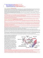
Step 3 - Electrocoating
A mixture of resin and binder and a paste containing the pigments are fed into a tank. The
vehicle is then lowered into the tank from an overhead conveyor and an electric current
applied. This car body becomes the cathode and the tank the anode in an electrocoating
reaction that results in a resin polymer being very tightly and evenly bound to the metal
surface of the car body.
Step 4 - Rinsing
The vehicle is rinsed several times, both with water and with a weak paint solution, to
remove a thin coat of paint that clings to the surface but hasn't bonded to the metal. If this
wasn't removed then the car would have an uneven, messy coat of paint.
Step 5 - Baking
The car body is then baked to 170 - 180
o
C in an oven. This causes the different polymer
chains to crosslink (i.e. bind to each other in many places) forming a very strong, flexible,
interconnected network of polymer over the whole surface of the car.
New types of paint are continually being designed which are more environmentally
friendly, longer lasting and more tolerant of steel defects such as oil being left on the steel.
INTRODUCTION
Vehicles need to be coated in some way to slow down the corrosion of the metal of which
they are made. A good vehicle surface coating will also be smooth and flexible and not be
easily chipped by stones. A number of different types of painting techniques have been tried
in the search to find one that cheaply and effectively fulfills these requirements. This article
covers the process most commonly used today: the cathodic electrocoating process. This
process coats the vehicle with a grey, corrosion-resistant undercoat known as a 'primer'. A
second layer of paint is later added to the vehicle to give it a more decorative coloured finish.
X-Polymers-F-Car Bodies-2
The brief history of car painting
Initially, car bodies were simply dipped into a vat of paint. Unfortunately, the paint didn't
usually cover the whole surface evenly so some areas were barely protected at all. In
addition, the paint used didn't protect well against salt corrosion.
1
In the early 1970s it was
found that cars could have paint electroplated onto them, using the car itself as the anode.
These coatings were a lot better than the earlier dip coatings, but they involved using a resin
with organic acid groups. These reacted with the zinc of zinc-coated steel (used to slow
down corrosion) so that the vehicles couldn't have the added protection of a zinc coating. In
addition, there remained some problems with coverage.
Now most vehicles are electrocoated using a cathodic process. This uses less electricity,
gives a coating that is more resistant to salt corrosion than either of the other methods, results
in good coverage and can be used in conjunction with zinc coated steels. In addition, the
bisphenol A epoxy resin system combined with urethane gives an outstanding combination of
mechanical properties and corrosion resistance. This system was not introduced earlier
because it involves the crosslinking of alkali, not acidic, groups to form the resin base. Until
the late 1970s no efficient means for doing this was known, but now it is standard practice.
Electrocoating has grown rapidly in popularity. The process was developed in the 1960's,
and by 1970 10% of all vehicles world wide were electrocoated. By 1990 this had increased
to 90% of all vehicles, and today it is by far the most commonly used vehicle coating process.
Electrocoating processes
The anodic process, like the dip process, is now only used for a small number of special
applications. However, it is included near the end of this article because it is of considerable
historic importance, being the first electrocoating method used for auto-body surface
coatings. The cathodic process is what is usually used, and it is essentially similar to the
anodic process, except that the process involves the crosslinking of basic, rather than acidic,
groups.
THE MANUFACTURING PROCESS
Auto bodies are coated with paint in a five step process. The steps are as follows:
• precleaning (to remove dirt and grease)
• phosphating (to provide a better surface for the paint and for additional corrosion
protection)
• electrocoating (the actual application of the paint)
• rinsing (to remove the "cream coat" of paint that hasn't bonded to the metal surface)
• baking (to crosslink the polymeric coating)
These steps are detailed below.
1
In countries such as the USA and Canada that have a lot of snow on the roads in winter, this snow is
removed from the roads by sprinkling it with salt. Unfortunately this salt also corrodes the underbodies of cars - a
process known as "salt corrosion".
X-Polymers-F-Car Bodies-3
Step 1 - Precleaning
Greases and oils interfere with the way the paint bonds to the metal surface, creating gaps in
the coating that encourage corrosion. For this reason, any greases deposited on the metal
during the assembly of the car body must be removed as early as possible. This is done by
dissolving the oil in kerosene and then removing the oil-solvent mixture. The car body is
then washed with alkali to complete the degreasing process and rinsed with water.
Step 2 - Phosphating
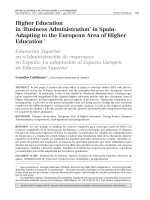
The steel that is used is layered (Figure 1), with the outer coating being primarily zinc. This
layer is sprayed with phosphoric acid (H
3
PO
4
) at 50 - 55
o
C. The acid reacts with the zinc to
give a mixture of zinc phosphates:
2H
3
PO
4
+ 3Zn → 3H
2
+ Zn
3
(PO
4
)
2
2H
3
PO
4
+ Fe + 2Zn → 3H
2
+ FeZn
2
(PO
4
)
2
This treatment leads to a marked improvement in corrosion resistance, both directly and by
helping the paint to stick. Phosphating and painting together offer 75 - 90% of the total
corrosion resistance and increase the life of the vehicle by 5 - 10 years.
Mild Steel Substrate
80:20 Zinc-Iron Alloy (20 g m )
-2
80:20 Zinc-Iron Alloy (20 g m )
-2
Figure 1 - Zinc-coated steel
Excess phosphoric acid is washed off with water and the vehicle body carried by an overhead
conveyor into an electrocoat tank.
Step 3 - Electrocoating
The electrocoat tank is of steel construction with an epoxy lining to provide corrosion
resistance and electrical insulation. The tank is designed to achieve the following processing
conditions:
- minimum size for economy whilst allowing ease of entry and rapid air pocket removal
from vehicles.
- good uniform circular flow to remove floated dirt and foam over a weir and to remove
settled dirt by front end filtration.
- paint returning from external filter lines from eductors prevent "dead spots" in the tank
which cause settlement and dirt generation.
- the horizontal movement of paint in the upper layer of the tank is at least twice that of the
vehicle. This helps to prevent settlement of paint of horizontal vehicle surfaces causing
gritty films.
Tanks which are operated in New Zealand are between 50,000 and 150,000 litres. Tanks are
pH controlled, and a cathode to anode area ratio of up to 4:1 is used.
X-Polymers-F-Car Bodies-4
Fresh paint and solvent are added to the tank as necessary. The paint is mixed and then
added continually (the rate being dependent on the rate at which vehicles are electrocoated)
to replace the paint solids being electrodeposited onto the vehicles. Solvent is only added as
it evaporates off, which occurs particularly rapidly in slow turnover tanks.
To keep the paint particles stable and discrete, it is necessary to cool the tank. Chillers and
heat exchangers are designed to hold the bath at a minimum temperature of 15
o
C under full
operating conditions. Individual types of electropaints have an optimum operating
temperature to achieve a good paint stability and good deposition characteristics.
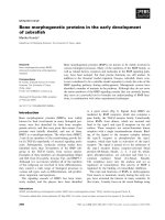
Paint composition
The paint is stored in two parts. One consists of the resin and binder, the other consists of the
pigments. Usually the resinous portion is an amine salt derivative of a bisphenol A epoxy
resin, with blocked isocyanate oligomers for the binder. This gives a very corrosion resistant,
resilient polyurethane system when crosslinked. This resin is formed using the same type of
mechanisms as that given below under "The Anodic Process". These components are shown
schematically below. The formation of a stabilised paint particle from the mixing of these
two components is shown in Figure 2.
OOC
CH
3
CH
3
OCH
2
CH
OH
RNH
3
+-
OOR
Polymer
Amine salt derivative of a bisphenol A epoxy resin
N
N
NC
H
OR"
O
Blocked isocyanate functional oligomer
2
binder (blocked with R"—OH)
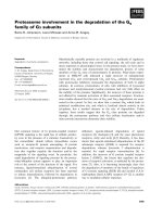
The physical and chemical reactions of electrodeposition
The electrodeposition process consists of four simultaneous electrochemical reactions and
physical effects (Table 1), which result in the formation of a film with considerable strength.
This strength enables the film to withstand heavy rinsing.
After electrocoating the vehicle bodies or components are carried by overhead conveyor
through a series of rinse stages.
Step 4 - Rinsing
The rinsing operation removes the thin layer of paint which adheres to vehicles leaving the
tank. The removal of this "cream coat" is essential in order to prevent film defects. The
process consists of a series of spray and dip rinses. The paint that is washed off during these
rinses is recycled and used again in the coating of more vehicles.
2
Oligomer: polymer with a small number of monomers
X-Polymers-F-Car Bodies-5
Figure 2 - A pigment particle is stabilised by resin
After rinsing, floor conveyors transport the vehicle to the oven for baking.
Step 5 - Baking
The vehicle is baked to a metal temperature of 170-180
o
C. During this process, chemical
crosslinking takes place. Urethane and urea linkages between the resin and binder are
formed, and the groups that blocked the urethanes earlier are liberated as volatiles together
with flow solvents and other cracking products.
RECENT DEVELOPMENTS
New types of cathodic electrocoatings are continually being developed to improve corrosion
performance, coating appearance and mechanical properties and to reduce the environmental
impact of the processes.
Corrosion performance
Higher film builds
It is now possible to get bisphenol A epoxy urethane resins with a film build of 28 - 35µm,
X-Polymers-F-Car Bodies-6
Table 1 - Changes taking place during electrodeposition
Cathode Anode
Electrophoresis
The positively charged paint particles
(RN
+
H
3
) are transported to the negatively
charged vehicle.
R
+
NH
3
OH
-
RNH
2
H
2
O
+
+
Precipitation
The paint particles react with hydroxide
ions which have been formed by H
2
O
electrolysis (see below). The amine salt
groups are destroyed causing precipitation.
Steel body
Cathode Anode
Electro-osmosis
Water solubles migrate from the film. The
resulting osmotic pressure "squeezes" out
water from the film.
Steel body
Cathode Anode
H
2
H
2
H
2
H
2
H
2
H
2
O
2
O
2
O
2
O
2
O
2
O
2
Electrolysis
O
2
is generated at the anode as follows:
2H
2
O → O
2
+ 4H
+
+ 4e
-
H
2
is generated on the vehicle itself:
H
2
O + 2e
-
→ H
2
+ 2OH
-
The H
2
ruptures the film giving it its
characteristic roughness before baking.
compared with the old standard of 18 - 23µm. This means that even in "salt corrosion"
countries it is possible to give six year guarantees on car paint systems.
Edge coverage electrocoatings
The surface tension of most electrocoatings cause pulling away and low coverage on edges
during the baking process. Electrocoatings manufacturers have designed systems to
overcome this problem using a number of techniques:
- restricting the flow characteristics of the resin
- using double coating techniques with separate baths
- using double layers which deposit one after the other from the same bath
The first two techniques are now utilized commercially with the third technique in a
X-Polymers-F-Car Bodies-7
development stage. Restricting the flow of a single bath material is adequate for small parts
plants where a high degreee of film smoothness is not required. On more visible areas of the
vehicle where film smoothness is essential for overall paint appearance, the problem of edge
coverage is overcome by having a two layer system. The first layer has had its flow
characteristics restircted, the second layer has a good flow to obtain film smoothness. A
double coating system has drawbacks in that two tanks are required, so there is a lot of
interest in the more technically difficult process of applying two layers from a single bath,
because of its financial advantages.
Zinc coated steels
Newer model vehicles are constructed mainly from zinc coated steels. A typical multi-
layered alloy coated steel is shown in Figure 1. The zinc is usually electroplated onto the
steel because this gives a smoother coating than that obtained if the steel is simply dipped
into hot zinc. The zinc rich alloy provides corrosion protection whilst the upper layer of iron
rich alloy is a good site for promoting optimum crystal growth during the phosphate
pretreatment process.
Coating smoothness and flow
The "glass like" finishes now observed on "top of the range" vehicle models are being used as
industry benchmarks for coating quality. The ability of the automotive manufacturer to
achieve paint smoothness depends on the quality of the steel substrate together with the flow
characteristics of the individual layers which form the total paint system. Paint smoothness is
measured using a profilometer to determine its roughness average (Ra). Typical Ra values in
microns are given in Table 2 for successive layers of a coatings system on mild steel.
Table 2 - Ra values for a total automotive paint system
Substrate or successive layer of coating
Ra range / µm
Bare mild steel
0.80 - 1.40
Phosphated steel
0.70 - 0.90
Electrocoating
0.17 - 0.35
Polyester surfacer
0.05 - 0.15
Clearcoat over basecoat enamel
0.04 - 0.09
The electrocoat smoothness can have a significant effect on the overall paint appearance after
topcoating.
The paint surface can also be given a rough appearance because of "crater" formation. If any
oil is left of the vehicle body after precleaning, during baking this oil boils, forming craters in
the surface. These are transmitted through the paint and are clearly visible in the topcoat.
ICI Paints is currently researching paint systems that don't form these craters, and has had
considerable success (Table 3).
The results demonstrate the superior cratering resistance of the newer type of cathodic
electrocoating.
X-Polymers-F-Car Bodies-8
Table 3 - The effect of oil contamination on cathodic electrocoatings
No. of craters on lab deposition
Electrocoat type
Without oil
Vehicle has some oil
coating
A typical standard film
build resin
3
500+
Newer medium film build
product
3
20
Other mechanical properties
Other mechanical properties such as stone chip resistance, flexibility and impact resistance of
the total paint system can be influenced by the design of the electrocoat polymer. The new
resin components can be individually tailored to achieve optimum coating mechanical
properties without sacrificing corrosion performance, deposition and appearance
characteristics of the electrocoating.
UTILITIES
Tank electrical system
The electricity for the electrocoating is provided from rectifiers capable of providing a
voltage between 0 and 500 V. Initially a heavy current is drawn, which then tails off during a
two minute deposition time, with an average of 250 - 320 V being used. The
electrodeposition process is self limiting because the paint insulates the vehicle such that a
point is reached where no more paint can be deposited.
Paint filtration
To prevent the paint from getting dirty the paint in the electrocoat tank is filtered continually,
with 2 -3 complete tank turnovers per hour. The filtration is done by drawing the paint
through a series of 50µm GAF bag type filters that remove dirt and separate out clumps of
paint particles. The paint is then returned to the tank.
Ultrafiltration
Water and low molecular weight species (solvents and short polymers) are removed from the
electrocoat tank by filtering the paint through a tubular membrane under pressure. The liquid
removed is known as permeate, and is used for spray rinsing the vehicles over the electrocoat
tank. In addition, some types of electrocoat contain low molecular weight species which are
undesirable at higher concentration. The presence of these materials can lead to high paint
conductivity and baked films of rough appearance, so they are removed by ultrafiltration at a
rate of about 12 litres per vehicle.
X-Polymers-F-Car Bodies-9
THE ANODIC PROCESS
The following sections describe the reactions used in the anodic process. These are
essentially similar to those of the cathodic process, but for the reasons outlined in the
introduction this process is only rarely used today.
MALOFA formation
Melanised linseed oil fatty acid (MALOFA) is one of the reagents used in resin formation. It
is formed in a Diels-Alder reaction.
O
O
O
O
O
O
+
Linseed oil Maleic MALOFA
fatty acid anhydride
Forming the bisphenol ester
This is the other major reagent used in making the resin. Bisphenol A is the starting material.
Na
+-
O
C
CH
3
CH
3
O
-+
Na
CH
2
CH CH
2
Cl
O
- NaCl
CH
2
OC
CH
3
CH
3
OCH
2
CHCH
2
O
CH CH
2
O
C
CH
3
CH
3
OCH
2
O
CH
2
CH OCH
2
CH
OH
O
O
CH
2
CHOCH
2
CH
3
CH
3
C
n
C
CH
3
CH
3
OCH
2
CH
2
CH OCH
2
CH
OH
OCH
2
CHOCH
2
CH
3
CH
3
C
OOH OH O
C
OR
C
RO
n
OH
C
OR
Forming the polymer
The MALOFA and ester are reacted together.
X-Polymers-F-Car Bodies-10
C
CH
3
CH
3
OCH
2
CH
2
CH OCH
2
CH
OH
OCH
2
CHOCH
2
CH
3
CH
3
C
OOH OH O
C
OR
C
RO
n
O
O
O
C
C
O
O
O
C
C
O
O
OR
C
RO
C
O
O
O
C
CH
3
CH
3
OCH
2
CH CH
2
O
OH
CHOCH
2
CHCH
2
CH
2
O
CH
3
CH
3
C
OH
OH
n
Emulsification
The polymer is reacted with a strong base to give it ionic groups in place of hydroxyl groups.
C
C
O
O
O
C
C
O
O
OR
C
RO
C
O
O
O
C
CH
3
CH
3
OCH
2
CH CH
2
O
OH
CHOCH
2
CHCH
2
CH
2
O
CH
3
CH
3
C
OH
OH
n
KOH
C
C
O
O
O
C
C
O
O
OR
C
RO
C
O
O
O
C
CH
3
CH
3
OCH
2
CH CH
2
O
O
-+
K
CHOCH
2
CHCH
2
CH
2
O
CH
3
CH
3
C
O
-+
K
O
-+
K
n
Electroplating
The paint that has been prepared in the preceding reactions is then fed into a tank in which
there is a car body. The car becomes the anode in an electrocoating process. Water
dissociates in solution, and the H
+
and OH
-
ions are then used both in the reactions at the
anode and in the reactions at the cathode. At the anode, the carboxylate groups are
neutralised:
RCOO
-
+ H
+
→ RCOOH
While at the cathode, KOH is regenerated and H
2
(g) is formed:
X-Polymers-F-Car Bodies-11
K
+
+ OH
-
→ KOH
2H
+
→ H
2
Baking
The vehicle is then baked in an oven, during which time the polymer coating hardens and sets
by a series of crosslinking reactions involving the unsaturated sites (double bonds).
CC
CC
C
C
C
C
CC
CC
THE ROLE OF THE LABORATORY
Various parts of the process are monitored to ensure optimum effficiency and coating
performance. These are listed in Table 4.
Table 4 - Parameters measured during various stages of surface coating
Electrocoat
tank
Ultrafiltrate
Anolyte
Dip rinse
pH
!
!
!
!
Conductivity
(µS cm
-1
)
!
!
!
!
Solids content
(% w/w)
!
!
!
Ash content
(% w/w)
!
Solvent content
(%w/w)*
!
!
!
MEQ
(A measure of acidity)*
!
Tank temperature
(
o
C)
!
Coulombic yield /
mg solid Coulomb
-1
*
!
*These tests are carried out by ICI on behalf of Toyota.
Other operating parameters monitored
Also monitored are:
• Conductivity of deionised water
• Body drip conducting prior to electrodeposition
• Bake temperature /
o
C
• Film thicknes / µm
X-Polymers-F-Car Bodies-12
ENVIRONMENTAL IMPLICATIONS
Electrodeposition has always been considered to be an "environmentally friendly" coatings
technology. The closed loop system ensures maximum paint usage and the major part of the
volatiles is water. However, some substances are of concern and these are considered below.
Volatile organic content
Electropaints have a significant volatile organic content (VOC). The VOC consists of the
following components:
- flow solvents
- blocking agents from the urethane crosslinker
- various cracking products
Volatile organic substances are of concern because they include many solvents that are toxic
to humans, and their volatile nature makes them easy to ingest. In addition, many volatile
organic substances contribute to smog.
The newer types of cathodic electrocoatings utilize resin systems which allow a lower level
of flow solvent to be used. These newer binders also employ crosslinkers which contain
significantly lower levels of blocking agents. The final resin system is desgned to give a
minimum level of cracking products generated by polymer degradation in the baking oven.
ICI Paints have developed cathodic electrocoatings that release just over half the typical
quantity of flow solvent, and research into blocking agents and flow solvents is continuing.
Energy consumption
Electrocoating consumes significant amounts of electricity, both during the electrolysis step
itself and during the baking stage. While the amount of electricity used for electrolysis
cannot be reduced, adopting coatings which are capable of being baked at lower temperatures
reduces energy consumption during baking. Newer types of cathodic electrocoatings contain
blocked isocyanate crosslinkers and catalyst systems which give cure at lower temperatures,
meaning that stoving temeperatures can be reduced from their current levels of 175 - 180
o
C.
These measures reduce the amount of electricity used, and hence the reduce the level of
environmental damage caused by electricity generation.
FINANCIAL ASPECTS
The cost of paint amounts to 15 - 20% of the total cost of making a vehicle (excluding
development costs), thus ways of cutting costs are continually being studied.
Written by Heather Wansbrough from information supplied by David Boyce (Thames High
School) and with reference to:
X-Polymers-F-Car Bodies-13
Publications
Berger, D. M. and Wint, R. F. ; New Concepts for Coating Protection of Steel Structures,
ASTM Special Technical Publication 841; American Society for Testing and Materials;
1984
Lister, Joe; A review of cathodic electrocoating and its impact on the corrosion
performance and paint quality of vehicles; ICI Paints; 1992
Roberts and Caserio; Basic Principles of Organic Chemistry; Benjamin; 1964
Schmael, W. R. and Purcell, John (eds); New Polymer Technology for Auto Body
Exteriors, AIChE Symposium Series, No. 260, Volume 84; American Institute of Chemical
Engineers; 1988
Internet
Envirosense; Advanced Zinc Phosphate Metal Pre-treatment; [Online] Available
October, 1996
Further information from a visit by Heather Wansbrough to Toyota New Zealand hosted by
Peter Sutcliffe.