Nervous System on a Chip Patent
Bạn đang xem bản rút gọn của tài liệu. Xem và tải ngay bản đầy đủ của tài liệu tại đây (1.2 MB, 15 trang )
See discussions, stats, and author profiles for this publication at: />
Nervous System on a Chip
Patent · May 2022
CITATIONS
READS
0
4
1 author:
Fredric Narcross
Ben-Gurion University of the Negev
5 PUBLICATIONS 0 CITATIONS
SEE PROFILE
Some of the authors of this publication are also working on these related projects:
Next in Time Memory View project
All content following this page was uploaded by Fredric Narcross on 19 June 2022.
The user has requested enhancement of the downloaded file.
US011347998B2
( 12 ) Narcross
United States Patent
( 10) Patent No .: US 11,347,998 B2
(45) Date of Patent :
May 31 , 2022
( 54) NERVOUS SYSTEM ON A CHIP
( 56 )
( 71 ) Applicant: Fredric William Narcross , Chillicothe,
OH (US)
(72 ) Inventor: Fredric William Narcross, Chillicothe ,
OH (US)
( * ) Notice:
Subject to any discla er, the term of this
References Cited
U.S. PATENT DOCUMENTS
2015/0106317 A1 *
4/2015 Rangan
2015/0120629 A1 *
4/2015 Matsuoka
2015/0248607 Al *
9/2015 Sarah
GOON 3/04
706/25
GOON 3/049
706/25
2015/0317557 A1 * 11/2015 Julian
patent is extended or adjusted under 35
U.S.C. 154 ( b ) by 1009 days.
GOON 3/049
706/44
GO6N 3/063
706/25
* cited by examiner
( 21 ) Appl. No .: 15 /905,730
Primary Examiner — Suchin Parihar
(74 ) Attorney, Agent, or Firm - Michael D. Eisenberg
( 22 ) Filed :
ABSTRACT
(57 )
A method to translate a nervous system model into Hard
ware Description Language ( HDL ) is presented here . The
nervous system model is that produced from the Nervous
Feb. 26 , 2018
( 65 )
Prior Publication Data
US 2019/0266477 A1
Aug. 29 , 2019
System Modeling Tool, patent application Ser. No. 15/660 ,
858 , and the HDL translation downloads into either aa Field
Programmable Gate Array (FPGA ) chip or an Application
(51 ) Int. Ci.
G06F 30/00
GO6N 37063
G06F 8/40
GO6F 30/323
G06F 30/34
( 2020.01)
( 2006.01 )
( 2018.01 )
( 2020.01 )
( 2020.01)
( 52 ) U.S. Cl .
CPC
GO6N 37063 ( 2013.01 ) ; GO6F 8/40
(2013.01 ) ; G06F 30/323 (2020.01 ) ; GO6F
30/34 (2020.01 )
( 58 ) Field of Classification Search
CPC
GOON 37063; G06F 30/326
USPC
703/11
Specific Integrated Circuit (ASIC ) architecture . The method
supports the neurobiological realism of Ser. No. 15 / 660,858
and adds massive parallelism operating at adjustable micro
chip speeds . A neurobiologically realistic nervous system
embedded on a microchip achieves the goal of neuromor
phic computing and thus embodies a nervous system on a
chip . The potential applications are extensive and cover the
range of robotics, big data analysis, medical diagnostics and
remediation , self - learning systems, and artificially intelli
gent applications such as intelligent assistants. Intelligent
assistants can be applied to the fields of language and
technology exposition , the Internet of Things ( IOT ) and
security.
See application file for complete search history.
8 Claims , 5 Drawing Sheets
1 Nervous System on a Chip
.
& Sirnulation
Environment
1
5 Create Output for
4 High - level
Simulation
Module HDL
}
so
??
?
f
2 Patent
I
I
1
I
10 Nervous
System HDL
Runtime
I
I
Modules
9 Hardware
Creation
1
Environment
3 Nervous
Application
System to HDL
Translator
Constructs
}
15660858
Nervous System
8 Create Output for
7 High- level
Hardware
Module HDL
?
{
U.S. Patent
May 31 , 2022
US 11,347,998 B2
Sheet 1 of 5
9
1 Nervous System on a Chio
6 Simulation
5 Create Output for
Environment
Simulation
1
I
H
4 High - level
?
?
?
Module HDL
{
{
2 Patent
10 Nervous
1
}
I
I
A
9 Hardware
Creation
Environment
System HDL
Nervous
System to HDL
Runtinte
Modules
Translator
$
3
3
3
}
3
Application
15660858
Constructs
Nervous System
8 Create Output for
7 High -level
?
?
?
Hardware
Module HDL
f
?
mann
3
Figure 1
2 Patent Application 15660858 Constructs Nervous System
1
1
1
1
1
1
1
1
}
}
A
}
1
20 System
21 Neurons
1
1
I
I
I
I
{
{
{
{
}
Builds
Neurons and
Astrocytes
22 Astrocytes
}
}
}
}
}
I
I
I
1
}
3
re
3
Figure 2
}
3
3
$
U.S. Patent
May 31 , 2022
US 11,347,998 B2
Sheet 2 of 5
9
3 Nervous System to HOL Translator
W
3
3
3
?
4 High - level
{
?
3
res
3
31 Build for
Module HOL
}
?
3
Simulation
22 Astrocytes
11 Control
2200 Astrocytes
2100 Neurons
21 Neurons
}
3
3
I
3
?
?
?
?
}
32 Build for
Hardware
Module HDL
3
Figure 3
31 Build for Simulation
I
I
I
A
311 Build for
Simulation
22 Astrocytes
21 Neurons
}
}
}
}
}
}
{
1
4 High - level
Module HDL
2200 Astrocytes
11 Control
2100 Neurons
{
{
1
I
I
I
}
}
}
}
312 Build for
Simulation 1
}
I
her
}
AM
Figure 4
Am
w
U.S. Patent
May 31 , 2022
US 11,347,998 B2
Sheet 3 of 5
9
311 Build for Simulation !
t
?
}
}
31101 Create
}
}
}
}
}
Simulation Header
11 Contra
31102 Process
21 Neurons
1
1
1
1
2100 Veurons
A
Simulation PASI
4 High - level
31103 Process Axon
Module HDL
Inputs and Outputs
{
A
31104 Process Astrocytes
}
}
}
}
}
E
Inputs and Outputs
22 Astrocytes
2200 Astrocytes
31105 Instantiate
}
1
Astrocytes
}
1
1
1
1
1
Figure 5
312 Build for Simulation it
}
?
w
}
w
W
M
w
W
31201 Instantiate
Neurons
}
}
}
1
.
}
}
21 Neurons
31202 Create
Simulation Begin
4 High -level
31203 Process
Module HDL
Simulation PNS I
}
1
1
A
I
t
2100 Neurons
11 Control
1
1
1
1
31204 Process Axons
Initialization
}
A
31205 Create
}
A
Finish
1
1
Figure 6
1
***
I
{
U.S. Patent
May 31 , 2022
US 11,347,998 B2
Sheet 4 of 5
32 Build for Hardware
w
MN
N N WW WWW w
*
*
W
* * * N W
W
w
W
w
M
M
M
MM
W
W
}
i
I
321 Build for
I
A
Hardware
22 Astrocytes
21 Neurons
I
7 High -level
1
Module HDL
11 Control
2200 Astrocytes
2100 Neurons
322 Build for
Hardware i
1
I
}
}
}
}
}
{
{
{
I
I
Figure 7
321 Build for Hardware
}
I
{
Y
32101 Create
Hardware Header
{
{
32102 Process
I
I
}
}
}
Hardware PNS
7 High- level
31103 Process Axon
Module HDL
Inputs and Outputs
}
31104 Process Astrocytes
Inputs and Outputs
{
31105 Instantiate
Astrocytes
{
}
Figure 8
.
I
E
11 control
Table
1
21 Neurons
2100 Neurons
1
1
1
1
1
.
2200 Astrocytes
E
22 Astrocytes
I
U.S. Patent
May 31 , 2022
US 11,347,998 B2
Sheet 5 of 5
9
322 Build for Hardware i
}
1
3
3
3
www www
3
{
31201 Instantiate
Neurons
}
32103 Create
}
1
}
3
3
w
3
21 Neurons
1
1
1
1
Hardware Begin
I
7 High - level
2100 Neurons
Module HDL
I
A
11 Control
{
31204 Process Axons
Initialization
}
1
}
1
1
1
31205 Create
Finish
}
}
*
Y
Y
Y
Figure 9
10 Nervous System HDL Runtime Modules
Wh
}
3
no
A
210 Neuron
220 Astrocyte
}
}
15660858 HOL Run - Time
15660858 HOL Run - Time
?
Fixed -Point Add
Fixed -Point Ada
Fixed -Point Multiply
Fixed -Point Multiply
3
}
{
{
?
$
3
Fixed -Point Division
1
}
Figure 10
US 11,347,998 B2
1
2
NERVOUS SYSTEM ON A CHIP
In still a further variant, the Nervous System to HDL
Translator comprises: filtering neurons and astrocytes data
bases for adynamic values ; and passing filtered values into
CROSS - REFERENCES TO RELATED
APPLICATIONS
5
U.S. application Ser. No. 14 / 821,738 , entitled BRAIN
U.S. application Ser. No. 15 / 660,858 , entitled NERVOUS
SYSTEM MODELING TOOL , filed Jul . 26 , 2017 are each
EMULATOR SUPPORT SYSTEM , filed Aug. 8 , 2015 and
either of a Build for Simulation module or Build for Hard
In another variant, the Build for Simulation module
comprises: a Build for Simulation I process ; and a Build for
Simulation II process.
ware module.
In a further variant, the Build for Simulation I process
, comprising gener
ating a timescale compiler directive to set a clocking fre
hereby
incorporated herein by reference in their respective 10 comprises:aCreate Simulation Header
entirety.
quency and timing resolution ; processing Simulation PNS I ,
comprising reading all filtered Neurons ; processing axon
TECHNICAL FIELD
inputs and outputs; processing astrocytes inputs and outputs;
and an Instantiate Astrocytes process, comprising construct
The subject technology is in the technical field of mod- 15 ing instantiated astrocyte modules within the Build for
eling nervous systems on microchip computing hardware Simulation module .
and encompasses the field of neuromorphic computing.
In yet another variant, the Build for Simulation II process
comprises: an Instantiate Neurons process, comprising con
BACKGROUND
structing instantiated neuron modules within the Build for
20 Simulation module for every neuron ; a Create Simulation
The technology's background stems from earlier work in Begin process ; a Process Simulation PNS II , comprising
the fields of nervous system modeling and simulation at the initializing PNS inputs and outputs to a default value ; a
Process Axons Initialization, comprising initializing layers
macro and micro levels of biological realism on traditional of
axon inputs per layer; and aa Create Finish process.
computing devices . The tool presented here is the culmina
In
still a further variant, the Build for Hardware module
tion of that research and further research on how to place the 25 comprises
: a Build for Hardware I process ; and aa Build for
previous nervous system models directly onto hardware Hardware
II process.
microchip devices or solid state media.
In another variant, the Build for Hardware I process
comprises: a Create Hardware Header, comprising generat
SUMMARY
ing
a timescale compiler directive to set a clocking fre
30
and timing resolution ; processing Hardware PNS I ,
The subject technology begins with the most comprehen quency
comprising
reading all filtered Neurons; processing axon
sive , detailed and accurate reproducer of nervous systems inputs and outputs
; processing astrocytes inputs and outputs;
available in the public sector and permits it to operate at and an Instantiate Astrocytes process, comprising construct
microchip speeds . It naturally integrates disparate input ing instantiated astrocyte modules within the Build for
types and incorporates extensible hardware input and output 35 Hardware module .
units . It supports inexpensive delivery on reconfigurable
In a further variant, the Build for Hardware II process
FPGA hardware and has wide applicability into leading edge comprises: an Instantiate Neurons process, comprising con
technologies and artificial intelligence applications.
structing instantiated neuron modules within the Build for
In aa variant, a method for modeling a nervous system on Hardware module for every neuron ; a Create Hardware
a chip , comprises, in a step (a) : translating a nervous system 40 Begin process ; a Process Axons Initialization, comprising
model into Hardware Description Language ( HDL ) and in a initializing layers of axon inputs per layer ; and a Create
Finish process.
step ( b ): translating runtime modules into HDL .
In another variant, the method comprises translating neu
BRIEF DESCRIPTION OF THE DRAWINGS
ron records of step ( a) into HDL .
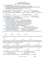
In further variant, the method comprises translating astro- 45 FIG . 1 illustrates 1 Nervous System on a Chip basic
cyte records of step (a ) into HDL .
, creation and operating environment.
In yet another variant, the method comprises translating components
FIG
.
2
illustrates
further detail of Constructs Nervous
neuron runtime modules of step ( b ) into HDL .
2.
In still a further variant, the method comprises converting System
FIG . 3 illustrates further detail of Nervous System to HDL
50
floating -point arithmetic to fixed -point arithmetic .
Translator 3 .
In another variant, the method comprises translating
FIG . 4 illustrates further detail of Build for Simulation 31 .
astrocyte runtime modules of step (b ) into HDL .
FIG . 5 illustrates further detail of 311 Build for Simula
In aa further variant, the method comprises the converting tion I.
floating -point arithmetic to fixed -point arithmetic.
FIG . 6 illustrates further detail of 312 Build for Simula
In yet another variant, a computer implemented method of 55 tion II .
simulating a nervous system on a solid state storage medium
and a processor, comprises: a Nervous System to Hardware
Description Language ( HDL ) Translator receiving the input
from a Constructs Nervous System process . The Nervous
I.
FIG . 7 illustrates further detail of 32 Build for Hardware.
FIG . 8 illustrates further detail of 321 Build for Hardware
FIG . 9 illustrates further detail of 322 Build for Hardware
System to HDL Translator translates the input into HDL 60 II .
code for an instantiated neuron and astrocyte modules '
FIG . 10 illustrates further detail of 10 Nervous System
parameters in a High - Level Module HDL . The method
comprises compiling by either a Create Output for Simula
tion process or by a Create Output for Hardware process .
HDL Runtime Modules.
DETAILED DESCRIPTION OF THE DRAWINGS
neuron runtime routines and translating them into HDL
FIG . 1 illustrates Nervous System on a Chip 1 basic
components and construction processes . First , input is
Nervous System HDL Runtime Modules are astrocyte and 65
modules.
US 11,347,998 B2
3
received from Constructs Nervous System 2 as disclosed in
patent application Ser. No. 15 / 660,858 . This input is further
detailed in FIG . 2. The input from 2 is received by Nervous
System to HDL Translator 3 , which translates the input into
HDL code for the instantiated neuron and astrocyte mod- 5
ules ' parameters in either 4 High - Level Module HDL or 7
High -Level Module HDL . The difference between these two
high - level HDL modules is that 4 is for when the user wants
to simulate the resultant system in software without a 10
delivery to hardware. Whereas, 7 is for delivery to either an
4
TABLE 2 - continued
2100 Neurons continued
Parameter
Description
2100151 A Pbdn
Number of Synapses
2100151 A PbdA
2100151 A PbdN
2100151 A PbdGA
AMPA value
NMDA value
GABA - A value
2100151 A PbdGB
2100151 A PbdD
Dopamine value
GABA - B value
FPGA or ASIC hardware device . This is further detailed in
2100151 A PbdS
Serotonin value
FIG . 3. Next, 10 Nervous System HDL Runtime Modules ,
whose components are detailed in FIG . 10 , are the astrocyte
2100151 A Pbde
Excitatory
2100151 A Pbdd
Dummy - user defined
and neuron runtime routines that were translated from the
patent application Ser. No. 15 / 660,858 JAVA language ver- 15
sions into HDL modules . The modules of 10 and 7 and 4 are
either compiled by 5 Create Output for Simulation when the
user chooses to run a simulation as represented by 6 Simu
lation Environment or compiled by 8 Create Output for
Hardware when the user chooses to create an FPGA or ASIC 20
hardware device as represented by 9 Hardware Creation
Environment.
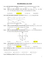
FIG . 2 illustrates detail of the Constructs Nervous System
2 process . 2 represents a basic goal of patent application Ser.
No. 15 / 660,858 to build a database of connected neurons
and a database of connected astrocytes. FIG . 2 consists of 20
System Builds Neurons and Astrocytes which is a basic
TABLE 3
2100 Neurons continued
Parameter
Description
210015 Pbd
2100152 Pbd
Basal Dendrites Parameters Layer 2
2100152 Pbdp
25
2100153 Pbd
2100152A Podp
Basal Dendrites Parameters
Short - term Synaptic Plasticity
Basal Dendrites Parameters Layer 3
Short - term Synaptic Plasticity
representation of the patent application Ser. No. 15 / 660,858
processes which create both the 21 Neurons database as well
as the 22 Astrocytes database .
30
2100156 Pbd
2100156A Pbdp
Basal Dendrites Parameters Layer 6
Short - term Synaptic Plasticity
FIG . 3 illustrates detail of 3 Nervous System to HDL
Translator. The goal of 3 is first of all to examine both the
21 Neurons and the 22 Astrocytes databases for dynamic
2100156A Pbdd
Dummy - user defined
values , as determined by 2100 Neurons and 2200 Astrocytes
respectively, which act as filters and pass those filtered 35
values into either of 31 Build for Simulation or 32 Build for The values from Table 1 , 21001 through 210014 , are
Hardware . The filtered values for 2100 are detailed in Tables
extracted per neuron from 21 Neurons and applied as HDL
1-3 .
module instantiation parameters in the high - level module for
40 either 4 High - Level Module HDL or for 7 High -Level
TABLE 1
Module HDL . The module instantiation parameters are
constructed by either 31 Build for Simulation or 32 Build for
2100 Neurons
Hardware respectively. For each neuron module instantiated
Description
Parameter
within a high - level module, 4 or 7 , there is only one copy of
21001 Pa
Spiking Dynamics
45 these parameters, which basically represent neuron soma
21002 Pb
Spiking Dynamics
parameters or apical dendrite parameters common to all
21003 PvPeakBD
Voltage Peak Basal Dendrite
apical dendrites for this neuron . On the other hand, Tables 2
21004 PvPeakSoma
Voltage Peak Soma
and 3 represent a collection of 96 permutations of the basal
21005 PcBD
Conductance Basal Denedrites
21006 PcSoma
dendrites that 1 Nervous System on a Chip supports. This
Conductance Soma
Spiking Dynamics
21007 Pc
50 includes 6 possible layers of apical dendrites with 16 pos
Spiking Dynamics
21008 Pd
sible basal dendrites per layer. Table 2 lists the entire entries
21009 Pe
Spiking Dynamics
Spiking Dynamics
210010 Pf
for
the first layer and first basal dendrite . Table 3 lists the
Spiking Dynamics
210011 Pg
repetitions
for the remainder of the 6 layers as well a
210012 Ph
Spiking Dynamics
Spiking Dynamics
Spiking Dynamics
210013 Pi
210014 Pj
shortened form for the 16 basal dendrites. The filtered values
55 for 2200 are detailed in Table 4 .
TABLE 4
TABLE 2
2100 Neurons continued
Parameter
Description
210015 Pbd
2100151 Pbd
Basal Dendrites Parameters
2100151A Podp
Short - term Synaptic Plasticity
Short - term Synaptic Plasticity Recovery
2100151 A Pbdt
Basal Dendrites Parameters Layer 1
2200 Astrocytes
60
Parameter
22001 Nn
22002 Nn
22003 Nn
65
22004 Nn
22005 An
22006 An
Description
Neuron Neighbor 1 ID
Neuron Neighbor 2 ID
Neuron Neighbor 3 ID
Neuron Neighbor 4 ID
Astrocyte Neighbor 1 ID
Astrocyte Neighbor 2 ID
US 11,347,998 B2
5
6
TABLE 4 - continued
each occurrence is assigned a new output port line with a
name given by parameter 11070 1 OutNamel .
2200 Astrocytes
Parameter
22007 An
22008 An
Description
Astrocyte Neighbor 3 ID
Astrocyte Neighbor 4 ID
FIG . 4 illustrates detail of 31 Build for Simulation . This
process creates 4 High - Level Module HDL which is the high
5 level HDL module to generate when the user wants to
construct a simulation and verify their design prior to
creating a high - level module for chip construction either in
FPGA or ASIC form . 31 begins with 311 Build for Simu
Parameters 2201 Nn through 2204 Nn are the neuron ids of lation I , which is the first half of the processes which create
those neurons surrounded by some particular astrocyte. The 10 4.311 is detailed in FIG . 5. 31 continues with 312 Build for
neurons' synaptic activity or lack thereof is recognized by Simulation II , which is the second half of the processes
the astrocyte , which in turn increases or decreases the which create 4. 312 is detailed in FIG . 6. Both of 311 and
surrounding capillaries diameter that in turn changes the 312 utilize input from 21 and 22 filtered through 2100 and
volume of blood flow through the capillaries . The capillaries 2200 respectively and detailed further in FIG . 3. The infor
blood flow provide a range of resources required for basal 15 mation
and filtered
is used
createandthe312instantiated
modulesgathered
' parameters
for 4. Also
, bothto 311
utilize 11
dendrite growth or pruning which places astrocytes in the
position of managing this change by dynamically adjusting
blood flow . This is the model of the tripartite synapse also
known
as the 2208
NeuralAnVascular
(NVU ).ids
Parameters
An through
are theUnitastrocyte
of the 2205
local
astrocytes connected by gap junctions to this particular
so as to distinguish which neurons from 21 might be either
PNS input or PNS output. This was also described in the
details of FIG . 3. As well , 11 is used to invoke 31 rather than
20 FIG
invoking
32 Build for Hardware. This was also described in
. 3.
FIG . 5 illustrates detail of 311 Build for Simulation I. 311
astrocyte. This supports the creation of an astrocyte network , begins with 31101 Create Simulation Header, which creates
which in turn provides for one astrocyte's activity to be the “ ?timescale ” compiler directive to set the clocking
communicated to its neighbors and vice versa . The thinking 25 frequency and timing resolution . This is set to a default of
behind why astrocyte networks are an advantage to nervous 100 ns with a 1 ps resolution . 31101 also sets 4's name to a
systems is that the communication of neuronal activity or the default of " test_bench ” . Next , 311 invokes 31102 Process
lack thereof provides advanced “ knowledge” of neuronal Simulation PNS I. 31102 reads all of the 21 Neurons filtered
activity which can modify capillary resources so as to through 2100 looking for both PNS inputs from 11 param
minimize the lag time of neuronal resource supply and 30 eter 11061 1 InTypel as well as PNS outputs from 11070 1
demand . This minimization of lag time to increase capillary OutTypel. Matching inputs receive a name of 11 parameter
resources or its opposite to minimize the total local blood 11061 1 InNamel followed by an integer which is incre
supply when there is no demand are both considered to be mented for each occurrence . For example, the first such
the result of evolutionary blood flow optimization . The brain occurrence would receive a name of in1Name_0 and the
would receive a name of in Name_1 . Matching
of humans, which account for about 2 % of total body mass 35 second receive
a name of 11 parameter 110701 OutNamel
but which account for 20 % of blood borne oxygen and outputs
followed
by
an
integer which is incremented for each
glucose consumption benefits greatly from neurophysiologi occurrence . For example
the first such occurrence would
cal optimization of resource consumption by astrocytes. receive a name of out1,Name_0
and the second would
Finally, 11 Control Table is a 2 patent application Ser. No. 40 receive a name of outlName_1, etc. All PNS inputs and
15 / 660,858 JAVA class which must be customized by the outputs are declared as one bit registers : “ reg” . Next, 311
user for use by 1 .
invokes 31103 Process Axon Inputs and Outputs . First of all ,
11 contains parameter 1101 SB which controls whether 31 for each neuron contained in 21 , 31103 sets up a maximum
or 32 is invoked . Parameter 1102 contains the text name of of 6 apical dendrite inputs each of which accept a maximum
the high- level module’s Start name input port line , which is 45 of 16 axon inputs. For example, for neuron id 0 there would
the name of the line that initializes or reinitializes the entire be 6 , 16 bit registers declared as reg [ 15 : 0 ] axon_0_in_1 for
system including all of the instantiated neurons and astro- layer I up to reg [ 15 : 0 ] axon_0_in_6 for layer VI . Then
cytes . Parameter 1103 contains the text name of the high- 31103 sets up a single axon output per neuron id from 21 .
level module's Clock name input port line , which is the For example, for neuron id 0 the declaration would become
name of the line that is passed to all instantiated neuron and 50 " wire axon_0 " . The neurons ' axons are all declared with a
astrocyte modules to control their clock signal and , in turn , " wire” designation since they interconnect modules. Next,
the frequency of all module operations. Parameter 1104 311 invokes 31104 Process Astrocytes Inputs and Outputs .
Neuron Size contains the number of 21 records to inspect . First of all , for each astrocyte contained in 22 , 31104 sets up
3
This allows the user to select a subset of neurons generated a wire output with a text name of " astro_out_id ” where id is
Astrocyte Size contains the number of 22 records to inspect . nicate to connected astrocytes . Then for each astrocyte
This allows the user to select a subset of astrocytes generated contained in 22 , 31104 sets up a wire output with a text name
by 2 as opposed to the entire collection . Parameter 11061 1 of “ arteriole_out_id ” where id is replaced by the astrocyte
InTypel indicates the neuron type of the peripheral nervous id . This output is used to communicate to connected neu
system that will be delivered from external sources, i.e. from 60 rons. Next, 311 invokes 31105 Instantiate Astrocytes , which
sources external to the microchip . This value is then constructs the instantiated astrocyte modules within 4. To
searched for within 21 and each occurrence is assigned a accomplish this, 31105 creates a unique module header for
by 2 as opposed to the entire collection . Parameter 1105 55 replaced by the astrocyte id . This output is used to commu
new input port line with a name given by parameter 11061 each astrocyte consisting of the text “ astrocyte ” , which is the
1 InNamel . Parameter 11070 1 OutTypel indicates the name of the astrocyte module, followed by the text
neuron type of the peripheral nervous system that will be 65 “ A_ID_id " where “ id ” is the astrocyte id number. For
delivered to external sources , i.e. to sources external to the
microchip . This value is then searched for within 21 and
example, " A_ID_O ” would be the astrocyte module instan
tiation for the astrocyte with id 0. Next, as required by HDL
US 11,347,998 B2
7
8
syntax , a " {" is inserted . Next, the port list for this astrocyte
is elaborated. The list begins with the text for the astrocyte
module’s neurons ' surrounded : “ .neuron_in ( {” . This is then
followed by the list of neurons ' surrounded which appear
hexadecimal number. This process is continued for all
parameters as represented in 2100 TABLE 3. When all of the
parameters are added then 31201 continues by adding the
port list for this particular neuron . To accomplish this 31201
from 2200's parameters 22001 through 22004 , and then 5 creates a unique module header name for each neuron
concatenated to a generic axon output text. For example, consisting of the text “ N_ID_id ” where " id " is the neuron id
“ axon_O ” is the generic axon output for neuron id 0. This is number. For example, “ N_ID_O ” would be the neuron
repeated for each neuron surrounded by this particular module instantiation for the neuron with id 0. Next, as
astrocyte. A complete example might look like : “ .neuron_in required by HDL syntax a “ ” is inserted. Next , the port list
( {axon_0, axon_1, axon_2, axon_3});”. Next, the text for the 10 for this neuron is elaborated. This begins with the text for the
astrocyte module’s astrocytes' connected ports is inserted : 16 neurons axon inputs for each apical dendrite. These 16
" astrocyte_in ( { ” . This is then followed by the list of astro- inputs are concatenated as a single 16 bit register with a
cytes connected to which appears from 2200’s parameters naming convention of axon_id_in_layer #. the register's
22005 through 22008 , and then concatenated to a generic name is surrounded by “ O ) ” and preceded by the neuron
astrocyte input text. For example, " astro_out_0 ” is the 15 module's axon input text per layer, “ .axon_in_layer # ”. “ id ”
generic input from astrocyte id 0. This is repeated for each is the neuron's id and “ layer # ” is the apical dendrite layer.
astrocyte connected to by this particular astrocyte. A com- For example, " .axon_in_1 (axon_0_in_1),” would indicate
plete example might look like: “ .astrocyte_in ( {astro_out_1, neuron id O's layer I 16 bit register. This is repeated for all
astro_out_2, astro_out_3, astro_out_4 } ),”. Next, the text for 6 layers, where each apical dendrite resides . Next , the text
the clock parameter is inserted into the module instantiation . 20 for the clock parameter is inserted into the module instan
This is a universal setting from 11 , parameter 1103 Clock , tiation . This is a universal setting from 11 , parameter 1103
and looks like , “ .clock ( clock_50 ),” for example when the Clock, and looks like, “ .clock (clock_50 ),” for example
clock parameter has been set to " clock_50 ” . Next , the text when the clock parameter has been set to “ clock_50 ” . Next,
for the start parameter is inserted into the module instantia- the text for the start parameter is inserted into the module
tion . This is a universal setting from 11 , parameter 1102 25 instantiation . This is aa universal setting from 11 , parameter
Start, and looks like, " .start ( start ) , ” when the start parameter 1102 Start, and looks like , " .start (start)," when the start
has been set to “ start ” . Next, the output for this particular parameter has been set to “ start ” . Next , the arteriole input
astrocyte, which communicates to astrocyte neighbors is managed by the astrocyte, which surrounds this particular
inserted, for example “ astro_out (astro_out_1),” for astro- neuron , is inserted . This takes the form of “ .arteriole_in
cyte id 1. Finally, the arteriole output for this astrocyte is set , 30 ( arteriole_out_0 ), " where the " out_0” indicates the arteriole
for example “ .arteriole_out ( arteriole_out_1) ”. The arteriole managed by astrocyte id 0. Finally, the axon output for this
output is the parameter which opens and closes the sur- particular neuron is elaborated . This takes the form of:
rounded neurons ' capillary blood supply.
“ .axon ( axon_1 )) ; " where “ _1” indicates neuron id 0 and the
9
FIG . 6 illustrates detail of 312 Build for Simulation II .
additional " );" is the HDL convention to end the port
31201 Instantiate Neurons, which constructs the instantiated
neuron modules within 4 for every neuron in 21. To accomplish this, 31201 creates a header for the neuron parameters
used by every neuron module : " neuron # ( ”. This is a
invoked . 31202 adds the HDL text “ initial” on one line
followed by the text “ begin ” on the next line . Next , 31203
Process Simulation PNS II is invoked to initialize the PNS
inputs and outputs to a default value of 0. Since these are all
This is the continuation of 311 from FIG . 5. 312 begins with 35 assignments. Next, 31202 Create Simulation Begin is
requirement of the HDL language when instantiated mod- 40 single bit values , input values are initialized to “ 1b'b0 ” , for
ules have parameters to be overridden as is the case with 1 example “ in Name_0 = 1'60 ;" would set the first PNS input
Nervous System on a Chip . “ neuron ” is the name of the HDL value to 0. For PNS output, the axon from the neuron
neuron module . Next and for each neuron instantiated, the providing the output would be connected to an output PNS
parameter values from TABLE 1 2100 Neurons are extracted name, for example " outlName_l =axon_3 ; " would connect
and translated into 16 bit values . For parameter 21001 Pa for 45 the first PNS output signal to the value from neuron id 3's
example, the following text would be constructed and added axon . Next, 31204 Process Axons Initialization is invoked to
to 4 for this neuron : “ 16'b0000000000000011, //Pa ” . Here , initialize the 6 potential layers of up to 16 axon inputs per
the original value of parameter Pa in some neuron has a layer. This requires every neuron from 21 to be filtered
value of 3 in decimal or 11 in binary. Each parameter is left through 2100 Neurons looking for the neuron's axon inputs
filled with zeros to create 16 total bits as is expected for the 50 per layer or the PNS inputs per layer. These results per layer
HDL neuron modules. The text “ //Pa ” is a comment for the are concatenated together according to HDL syntax and if
user indicating that this is the Pa parameter's value . Next , any layer's axon inputs do not exist then they are replaced
the parameter values from TABLE 2 2100 are extracted and with single bits of zeros . For example ,
converted to hexadecimal values and concatenated into a " axon_3_in_3 = {axon_0, axon_1 , axon_2 , 1'60 , 1'60 , 1'60 ,
single line of code. This is repeated for every basal dendrite, 55 1'60 , 1'60 , 1'60 , 1'60 , 1'60 , 1'60 , 1'60 , 1'60 , 1'60 , 1'60 } ;"
up to a maximum of 16 basal dendrites per layer, and is would initialize neuron 3's layer 3 with axon inputs from
repeated for up to a maximum of 6 layers . For example, the neuron id 0 , neuron id 1 and neuron id 2 and the rest of the
following might be generated for some neuron for its layer inputs are non - existent and take on default values of 0. In
III basal dendrite number 1 : “ 80'h26660096000411220010 , case a neuron's inputs come from a PNS input resource then
//Pin3_1_ptnANGGDSed ”. The interpretation here is that 80 60 the input name follows the PNS input naming convention for
bits are being represented as hexadecimal digits beginning the input in question.
For example,
with parameter 2100151A Pbdp and concluding with param- “ axon_4_in_4 = { in1Name_0, 1'60 , 1'60 , 1'60 , 1'60 , 1'60 ,
eter 2100151A Pbdd . The first 3 parameters, 2100151A 1'60 , 1'60 , 1'60 , 1'60 , 1'60 , 1'60 , 1'60 , 1'60 , 1'60 , 1'60 } ; "
Pbdp to 2100151A Pbdn are 4 hexadecimal digits in length would indicate that neuron id 4’s layer 4 has a single input
and the final 8 parameters, 2100151A PbdA to 2100151A 65 from PNS input “ in1Name_0 ” . Finally , 312 invokes 31205
Pbdd are single digit hexadecimal numbers, i.e. each parameter is four bits in length and represented as a single
Create Finish to add the text " end " followed by the text
“ endmodule ” and that completes 4. However, if the user
US 11,347,998 B2
9
10
wants to create the simulation by providing specific axon
input values over some extended repeated number of cycles
then the user must modify 4’s code between the “ begin ” and
“ end” text. This would typically be in the form of a loop
within which specific axons are initialized to specific values 5
For example, for neuron id 0 the declaration would become
“ wire axon_0 ” . The neurons' axons are all declared with a
" wire” designation since they interconnect modules. Next,
321 invokes 31104 Process Astrocytes Inputs and Outputs .
First of all , for each astrocyte contained in 22 , 31104 sets up
all of which must be customized according to user require- a wire output with a text name of “ astro_out_id ” where id is
ments .
replaced by the astrocyte id . This output is used to commu
FIG . 7 illustrates detail of 32 Build for Hardware . 32 nicate to connected astrocytes. Then for each astrocyte
builds the 7 High -Level Module HDL , which is the output contained in 22 , 31104 sets up a wire output with a text name
for a high - level module destined for elaboration into an 10 of “ arteriole_out_id ” where id is replaced by the astrocyte
FPGA or ASIC device . 32 begins with 321 Build for id . This output is used to communicate to connected neu
Hardware I , which is the first half of the processes which rons. Next, 321 invokes 31105 Instantiate Astrocytes, which
constructs the instantiated astrocyte modules within 7. To
Build for Hardware II , which is the second half of the accomplish this, 31105 creates a unique module header for
processes which create 7. 322 is detailed in FIG . 9. Both of 15 each astrocyte consisting of the text “ astrocyte ” , which is the
321 and 322 utilize input from 21 and 22 filtered through name of the astrocyte module , followed by the text
2100 and 2200 respectively and detailed in FIG . 3. The “ A_ID_id ” where " id " is the astrocyte id number. For
information gathered and filtered is used to create the example, “ A_ID_O ” would be the astrocyte module instan
instantiated modules ' parameters for 7. Also , both 321 and tiation for the astrocyte with id 0. Next, as required by HDL
322 utilize 11 so as to distinguish which neurons from 21 20 syntax, a " {" is inserted . Next, the port list for this astrocyte
might be either PNS input or PNS output. This was is elaborated. This begins with the text for the astrocyte
described in the details of FIG . 3. As well , 11 is used to module’s neurons ’ surrounded : “ .neuron_in ( { ”. This is then
invoke 32 rather than invoking 31 Build for Simulation . This followed by the list of neurons ' surrounded which appear
was also described in FIG . 3 .
from 2200's parameters 22001 through 22004 , and then
FIG . 8 illustrates detail of 321 Build for Hardware I. 321 25 concatenated to a generic axon output text. For example,
begins with 32101 Create Hardware Header, which creates " axon_0 ” is the generic axon output for neuron id 0. This is
the “ timescale ” compiler directive to set the clocking fre- repeated for each neuron surrounded by this particular
quency and timing resolution. This is set to 100 ns with aa 1 astrocyte . A complete example might look like: “ .neuron in
ps resolution . 32101 also sets 7's name to a default of ( {axon_0, axon_1, axon_2, axon_3 } ) ; ” . Next, the text for the
“ BESS3_syn ” . Next, 321 sets up the high- level module's 30 astrocyte module's astrocytes' connected ports is inserted :
header which must be synthesizable , i.e. a module header “ astrocyte_in ( {” . This is then followed by the list of
following HDL hardware device conventions. To accom- astrocytes connected to which appears from 2200’s param
plish this 32101 sets up the port list for 7. This is synergistic eters 22005 through 08 , and then concatenated to a
to the actual port names which the hardware device will use generic astrocyte input text . For example , " astro_out_O ” is
and requires the user to follow up these definitions with 35 the generic input from astrocyte id 0. This is repeated for
those set up for the hardware device . First of all , a start/ reset each astrocyte connected to this particular astrocyte. A
input port must be named and this defaults to “ start ” . Next, complete example might look like : " astrocyte_in ({as
create 7. 321 is detailed in FIG . 8. 32 continues with 322
a clock input port must be named and this defaults to tro_out_1 , astro_out_2 , astro_out_3, astro_out_4 } ) ;”. Next,
“ clock ” . Thus far the output from 32101 looks like “ module the text for the clock parameter is inserted into the module
BESS3_syn ( input start, input clock ,” using the above 40 instantiation . This is a universal setting from 11 , parameter
assumptions . Next, 321 invokes 32102 Process Hardware 1103 Clock , and looks like, “ .clock (clock_50 ) , " for example
PNS to continue the module header. 32102 reads all of the when the clock parameter has been set as " clock_50 ” . Next,
21 Neurons filtered through 2100 looking for both PNS the text for the start parameter is inserted into the module
inputs from 11 parameter 11061 1 InTypel as well as PNS instantiation. This is a universal setting from 11 , parameter
outputs from 110701 OutType1. Matching inputs receive a 45 1102 Start, and looks like , " .start ( start) ,” when the start
name of 11 parameter 11061 1 InNamel followed by an parameter has been set as “ start ” . Next, the output for this
integer which is incremented for each occurrence . For particular astrocyte , which communicates to astrocyte
example , the first such occurrence would receive a name like neighbors is inserted, for example " .astro_out (as
inidName_0 and the second would receive a name like tro_out_1),” for astrocyte id 1. Finally, the arteriole output
inidName_1, where the “ id” indicates the neuron id . These 50 for this astrocyte is set , for example " .arteriole_out (arterio
names must be preceded with a port designation of “ input” , le_out_1 ) ” . FIG . 9 illustrates detail of 322 Build for Hard
for example “ input in Name_0," names the high - level mod- ware II . This is the continuation of 321 from FIG . 8. 322
ule's input port named “ in1 Name_0 ," as the first PNS input begins with 31201 Instantiate Neurons, which constructs the
port for the neuron whose id is 1. The second PNS input port instantiated neuron modules within 7 for every neuron in 21 .
for the neuron whose id is 1 would be named “ inlName_1 ," . 55 To accomplish this, 31201 creates a header for the neuron
This process is continued for matching PNS outputs , which parameters used by every neuron module : “ neuron # (” . This
receive the name of the PNS neuron's axon . For example , if is a requirement of the HDL language when instantiated
neuron id 3 was designated as a PNS output neuron then the modules have parameters to be overridden as is the case with
port designation would be " output axon_3 ” . The port des- 1 Nervous System on a Chip. “ neuron ” is the name of the
ignations are terminated with a “ ) ;". Next, 321 invokes 60 HDL neuron module . Next and for each neuron instantiated ,
31103 Process Axon Inputs and Outputs . First of all , for each the parameter values from TABLE 1 2100 Neurons are
neuron contained in 21 , 31103 sets up a maximum of 6 extracted and translated into 16 bit values . For example, for
apical dendrite inputs each of which accept a maximum of parameter 21001 Pa , the following text would be con
16 axon inputs . For example, for neuron id 0 there would be
structed and added to 4 for this neuron :
6 , 16 bit registers declared as reg [ 15 : 0 ] axon_0_in_1 for 65 “ 16b0000000000000011 , // Pa ” . Here, the original value of
layer I up to reg [ 15 : 0 ] axon_0_in_6 for layer VI . Then parameter Pa in some neuron has aa value of 3 in decimal or
31103 sets up a single axon output per neuron id from 21 . 11 in binary. Each parameter is left filled with zeros to create
?
2
US 11,347,998 B2
11
12
then the input name follows the PNS input naming conven
tion for the input in question. For example ,
16 total bits as is expected for the HDL neuron modules. The
text “ //Pa ” is a comment for the user indicating that this is
the Pa parameter's value . Next , the parameter values from
" axon_4_in_4 = { in1Name_0, 1'60 , 160, 1'60 , 1'60 , 1'60 ,
TABLE 2 , 2100 are extracted and converted to hexadecimal 1'60 , 1'60 , 1'60 , 1'60 , 1'60 , 1'60 , 1'60 , 1'60 , 1'60 , 1'60 } ;"
values and concatenated into a single line of code. This is 5 would indicate that neuron id 4’s layer 4 has a single input
repeated for everybasal dendrite per layer up to a maximum from PNS input “ in1 Name_0" . Finally, 322 invokes 31205
of 16 and repeated again for up to a maximum of 6 layers . Create Finish to add the text " end " followed by the text
For example, the following might be generated for some “ endmodule” and that completes 7 .
neuron for its layer III basal dendrite number 1 :
FIG . 10 illustrates detail of 10 Nervous System HDL
“ 80'h26660096000411220010 , // Pin3_1_ptnANGGDSed ”. 10 Runtime Modules. These are the two runtime modules
The interpretation here is that 80 bits are being represented recovered from patent application Ser. No. 15 / 660,858
as hexadecimal digits beginning with parameter 2100151A which have been converted into HDL from JAVA . There are
Pbdp and concluding with parameter 2100151A Pbdd . The three significant changes required for 210 Neuron and 220
first 3 parameters, 2100151A Pbdp to 2100151A Pbdn are 4
hexadecimal digits in length and the final 8 parameters,
2100151A PbdA to 2100151A Pbdd are single digit hexadecimal numbers, i.e. each parameter is four bits in length
and represented as a single hexadecimal number. This process is continued for all parameters as represented in 2100
TABLE 3. When all of the parameters are added then 31201
continues by adding the port list for this particular neuron .
To accomplish this 131201 creates a unique module header
name for each neuron consisting of the text “ N_ID_id"
where “ id ” is the neuron id number. For example, “ N_ID_O ”
would be the neuron module instantiation for the neuron
with id 0. Next , as required by HDL syntax , a “ (" is inserted .
Next, the port list for this neuron is elaborated . This begins
with the text for the 16 neurons axon inputs for each apical
dendrite. These 16 inputs are concatenated as a single 16 bit
register with a naming convention of axon_id_in_layer # .
The register's name is surrounded by “ C ” and preceded by
the neuron module’s axon input text per layer, " axon_in_
layer # ” . “ id ” is the neuron's id and “ layer# ” is the apical
dendrite layer. For example , " axon_in_1 ( axon_0_in_1) , ”
would indicate neuron id O's layer I 16 bit register. This is
repeated for all 6 layers , where each apical dendrite resides .
Next, the text for the clock parameter is inserted into the
module instantiation . This is a universal setting from 11 ,
parameter 1103 Clock , and looks like , “ .clock ( clock_50 ), ”
for example when the clock parameter has been set as
" clock_50 ” . Next, the text for the start parameter is inserted
into the module instantiation . This is aa universal setting from
11 , parameter 1102 Start, and looks like, " .start ( start ),”
when the start parameter has been set as “ start” . Next, the
arteriole input managed by the astrocyte, which surrounds
this particular neuron , is inserted . This takes the form of
“ arteriole_in ( arteriole_out_0 ), " where the “ out_0 ” indicates the arteriole managed by astrocyte id 0. Finally, the
axon output for this particular neuron is elaborated . This
takes the form of: " .axon (axon_1));” where “ _1 ” indicates
neuron id 0 and the additional “ ) ;" is the HDL convention to
end the port assignments . Next, 32103 Create Hardware
Begin is invoked to add the HDL text “ initial ” on one line
followed by the text "begin ” line . Next, 31204 Process
Axons Initialization is invoked to initialize the 6 potential
layers of up to 16 axon inputs per layer. This requires every
neuron from 21 to be filtered through 2100 Neurons looking
for the neuron's axon inputs per layer or the PNS inputs per
layer. These results per layer are concatenated together
according to HDL syntax and if any layer's axon inputs do
not exist then they are replaced with single bits of zeros. For
example , “ axon_3_in_3 = { axon_0, axon_1, axon_2 , 1'60 ,
Astrocyte, from their patent application Ser. No. 15 / 660,858
15 counterparts. First are modifications from the heavy use of
20
25
30
35
40
floating -point arithmetic in Ser. No. 15 / 660,858 to the use of
fixed - point arithmetic in 1 Nervous System on a Chip .
Floating -point arithmetic on FPGA and ASIC devices is
problematic due to the necessity of a single floating -point
processor unit (FPU) to be embedded on the devices . Some
devices have FPUs but most don't . And even when they do
it would require all 210 and 220 modules to access the same
FPU , which would eliminate the massive parallel nature of
1. Consequently, each 210 and 220 module instantiated has
its own self - contained fixed -point arithmetic processing and
thus massive parallelism can be obtained and results in a
more biologically realistic system . There are many examples
of fixed -point arithmetic that can be implemented on FPGA
or ASIC devices but none of them match what is required for
210 and 220 in optimum form . The routines used here are
unique in that they have been optimized for 1. This means
that the entire range of input and output values for each
calculation in each module have been determined a -priori
and the routines have been optimized around this knowl
edge. As well , the code that calls these fixed -point routines
presets the inputs to the same alignment of the decimal point
regardless of whether the inputs are 16 or 32 bits or a
combination . There are no 64 bit inputs. Also , the calling
code sets bit 31 of both inputs to the sign bit ; either 0 for
positive valued or 1 for negative valued . Also , all the
arithmetic routines setup temporary results registers and
then in the final step of the routine the temporary result is set
to the output variable’s result . This prevents the calling code
from receiving incomplete results . Finally , all the calling
45 code has been setup to avoid the possibility of overflows, so
no overflow bit is returned to the calling code . The first
fixed -point routine implemented within both 210 and 220 is
fixed -point addition , which is displayed in FIG . 10 as
Fixed -Point Add ( FPA ). FPA checks the sign bits for equiva
50 lence . If equivalent then addition using an HDL “ + ” operator
is performed and the results are placed in an output register.
The sign bit of the output is set to the first input. If the sign
bits are not the same then subtraction is performed using the
- " HDL operator by subtracting the smallest absolute value
55 quantity from the largest. Then the sign bit is set according
to 4 possible conditions: if the first input is positive and
greater in absolute value then the result sign bit is positive ;
if the first input's sign bit is positive and the absolute value
is smaller then the result sign bit is negative ; if the second
60 input is negative and is smaller in absolute value then the
output sign bit is positive; if the second input is negative and
greater in absolute value then the output sign bit is negative .
1'60 , 160 , 1'60 , 1'60 , 1'60 , 160 , 1'60 , 1'60 , 1'60 , 1'60 , 1'60 , The second fixed -point routine implemented within both
1'60 }; " would initialize neuron 3’s layer 3 with axon inputs 210 and 220 is fixed -point multiplication , which is displayed
from neuron id 0 , neuron id 1 and neuron id 2 and the rest 65 in FIG . 10 as Fixed - Point Multiply ( FPM ) . FPM sets up a
.
of the inputs are non - existent and take on default values of
0. In case a neuron's inputs come from aa PNS input resource
temporary 64 bit result register to store the initial result of
multiplying two 31 bit registers together. Then the multipli
US 11,347,998 B2
14
13
cand and multiplier inputs, without the sign bits , are multiplied together using the HDL “ * ” operator. The sign bit of
the result is set to the logical ‘ or ' of the two inputs using the
HDL “ ng operator. Finally, the temporary results are loaded
into the FPM's return variable. The final fixed -point arithmetic routine is Fixed -Point Division ( FPD ) . This routine is
only used twice in the neuron module ; is not used at all in
the astrocyte module . The runtime modules have been
optimized to avoid division since its usage is costly in HDL
synthesized form . As such , FPD emulates division and never
uses the HDL “ / ” operator. First , the sign bit of the temporary quotient is set by performing a logical OR between the
input divisor's and input dividend's sign bits . Then a loop
counter is established equal to the results of: 32 + decimal
point - 1. During each loop the divisor is divided by 2 which
is to say it is right -shifted by 1 , i.e. “ >> 1 ” . Then 1 is
subtracted from the loop counter . Next, a check is done to
see if the dividend is greater than or equal to the divisor, i.e.
are we working on integer values or decimal values for the
temporary quotient at this point in the division. If still
working on integer values then we subtract the divisor from
the dividend and assign the result to the dividend . Also , we
set the bit of the temporary quotient pointed to by the loop
counter to 1 , i.e. = 1'61 . Now , if the loop counter equals 0
then it is time to stop . At this point the temporary quotient
is loaded into the FPD output quotient, the remainder is
loaded into the output quotient post decimal point and the
FPD output quotient's sign bit is loaded from the temporary
quotient sign bit . The second set of modifications necessary
less than or greater than biological systems. This flexibility
gives the user complete control of the relative timing char
acteristics of the resultant model. Finally, Nervous System
on a Chip achieves neuromorphic computing on economical
5 FPGA hardware at an extensible scale , which has applica
bility to many important leading edge fields: for corporate
and personal use the resultant hardware can be integrated
together under the Internet of Things (IOT ) umbrella into
arrays of integrated processes supporting both home and
analyses can be integrated across disparate domains such as
vision and hearing data. For robots , the ability to have a
20 centralized control system supported by peripheral pro
cesses all of which are operating at microchip speeds as well
as being integrated together under the same architecture has
significant advantages similar to those performed naturally
by biological systems . Given that biological systems can
25 display intelligence and given that the Nervous System
Modeling Tool can reproduce nervous systems and given
that the Nervous System on a Chip can operate or surpass
biological operating speeds then the following artificial
intelligence pursuits are tenable by Nervous System on a
both 210 and 220 and the additional use of HDL module
analysis with incomplete information, interpretation of emo
10 factory automation . This integration of disparate processes
is performed naturally by biological systems and is a resul
tant advantage of The Nervous System Modeling Tool: when
placed into hardware nervous systems support the inclusion
of many disparate processes together, e.g. TVs , lighting,
15 heating, refrigerators, sound systems , etc. For Big Data
Analysis the resultant hardware can be used as accelerators
for significantly faster data analysis processing . As well , the
for the run -time routines is the use of HDL module ports for 30 Chip : language processing and understanding, planning,
parameters for 210. The ports and parameters for the instan- tions , self - learning and autonomous behavior.
tiated versions of 210 and 220 were detailed in FIG . 5 , FIG .
What is claimed is :
6 and repeated in FIG . 8 and FIG . 9. The third modification
1. A method of simulating a nervous system on a solid
required for 210 and 220 and massive parallelism of 1 is that 35 state storage medium, comprising:
in Ser. No. 15 / 660,858 there is aa central module which scans
receiving the input from a Constructs Nervous System
through every neuron and astrocyte module for each time
process by a Nervous System to Hardware Description
step and gives each such module an opportunity to update
Language (HDL ) Translator;
themselves . In 1 there is no requirement for such a central
translating the input into HDL code for an instantiated
module required to activate each 210 and each 220 because 40
neuron and astrocyte modules ' parameters in a High
each module operates independently all the time and any
Level Module HDL by the Nervous System to HDL
change to any module's input ports is enough to activate it ;
Translator;
otherwise the module and its circuits are silent, which
compiling the HDL code by either a Create Output for
ultimately conserves power resources and is again more
Simulation process or by a Create Output for Hardware
45
process; and
biologically realistic .
translating Nervous System HDL Runtime Modules into
Advantages
HDL modules comprising astrocyte and neuron run
time routines.
The ability to place nervous system models striving for
2. The method of claim 1 , wherein the Nervous System to
neurophysiologically realism onto microchip hardware 50 HDL Translator is configured to :
devices such as field programmable gate arrays (FPGAs) or
filter neurons and astrocytes databases for dynamic val
application - specific integrated circuits (ASICs) has signifi
ues ; and
cant advantages over older technology, which place nervous
pass filtered values into either of a Build for Simulation
system models onto either general purpose computing
devices employing central processing units (CPUs ), which 55
module or Build for Hardware module .
3. The method of claim 2 , wherein the Build for Simu
are sequential in nature, or even those that use CPUs but lation module comprises:
additionally employ graphic processing units (GPUs ) for a
a Build for Simulation I process ; and
partial boost in parallelism . First of all , in real nervous
a Build for Simulation II process.
systems all the neurological entities, including neurons ,
4. The method of claim 3 , wherein the Build for Simu
astrocytes and their processes, operate in parallel which is 60 lation I process comprises:
impossible for CPU or CPU devices assisted by GPUs to
a Create Simulation Header, comprising generating a
reproduce at the scale of millions of neurons and astrocytes .
timescale compiler directive to set a clocking frequency
The method presented here, however, operates every neuron
and timing resolution ;
and every astrocyte in parallel in hardware thus alleviating
processing Simulation PNS I , comprising reading all
the older technology's key hindrance lack of parallelism . 65
filtered Neurons;
A further advantage of this method includes timing control
processing axon inputs and outputs;
of the exact frequencies of operation including frequencies
processing astrocytes inputs and outputs; and
US 11,347,998 B2
16
15
an Instantiate Astrocytes process, comprising constructing instantiated astrocyte modules within the Build for
a Create Hardware Header, comprising generating a tim
escale compiler directive to set a clocking frequency
Simulation module .
5. The method of claim 3 , wherein the Build for Simulation II process comprises:
5
an Instantiate Neurons process , comprising constructing
processing astrocytes inputs and outputs; and
instantiated neuron modules within the Build for Simu
lation module for every neuron ;
a Create Simulation Begin process ;
a Process Simulation PNS II , comprising initializing PNS
inputs and outputs to a default value ;
a Process Axons Initialization , comprising initializing
layers of axon inputs per layer , and
a Create Finish process .
6. The method of claim 2 , wherein the Build for Hardware
module comprises:
a Build for Hardware I process; and
a Build for Hardware II process .
7. The method of claim 6 , wherein the Build for Hardware
I process comprises:
View publication stats
and timing resolution ;
processing Hardware PNS I , comprising reading all fil
tered Neurons;
processing axon inputs and outputs ;
an Instantiate Astrocytes process , comprising construct
ing instantiated astrocyte modules within the Build for
10
Hardware module .
8. The method of claim 6 , wherein the Build for Hardware
II process comprises :
an Instantiate Neurons process , comprising constructing
instantiated neuron modules within the Build for Hard
15
ware module for every neuron ;
a Create Hardware Begin process;
a Process Axons Initialization , comprising initializing
layers of axon inputs per layer ; and
a Create Finish process .