Integrating Electronic Equipment and Power into Rack Enclosures pot
Bạn đang xem bản rút gọn của tài liệu. Xem và tải ngay bản đầy đủ của tài liệu tại đây (2 MB, 65 trang )
Integrating Electronic Equipment and Power into Rack Enclosures
Optimized Power Distribution and Grounding for Audio, Video and Electronic Systems
Technical (isolated)
“single-point” ground bar
on insulators
MAIN PANEL SUB PANEL (optional)
Ground
Bar
Neutral &
Ground Bar
Grounded
Conductor
(Neutral & Ground
combined)
Neutral
(On insulators)
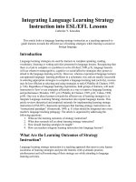
Isolated ground outlet conventional outlet
Technical (isolated)
ground wire terminated
in main panel only
(no connection to sub
panel ground)
Building ground
wire or conduit
Enclosure
From
Transformer
Grounded
Conductor
(neutral)
Grounding
Conductor
Rev. 4b
Table of Contents
Preface 1
A Note about Signal Paths 2
Ground Loops and Signal Interconnections 2
Signal Wiring: Unbalanced & Balanced Interfaces 3
AC Magnetic Fields & Their Effect on Signal Wiring 4
Electric Fields & Their Effect on Signal Wiring 5
Radio Frequency Interference (RFI) 5
Important Things to Remember When Designing & Installing Audio/Video Systems 6
North American Product Safety Certification 7
Dealing With Electrical Inspectors and Electrical Contractors 8
Typical 120-Volt Receptacles Used For Electronic Equipment 9
Receptacle Wiring - Common Errors and the Correct Way 10
AC Power Wiring Types 11
AC Magnetic Field Strengths from Different Wiring Types 13
Calculating System Load 13
Calculating Amplifier Circuit Requirements 15
Single Circuit Sequencer Systems 16
Multiple Circuit Sequencer Systems 17
Simplified Grounding Guidelines for Audio, Video and Electronic Systems 18
Isolation Transformers (Separately Derived Systems): Benefits and Wiring Methods 19
Isolation Transformer Neutral-Ground Bonding Methods 20
Electrostatic (Faraday) Shielding in Power Transformers 22
K-Rated Three Phase Power Transformers 23
Typical Three Phase Services 24
Phasing of Supply Conductors 25
60/120V Symmetrical (Balanced) Power Systems 26
Ground Myths 28
Neutral-Ground Reversals and Bootleg Grounds 29
Neutral-Ground reversals 30
Steps to Troubleshoot Bootleg Grounds and Neutral-Ground Reversals 32
Auxiliary Ground Rods 34
Intersystem Bonding (Cable TV, Satellite TV, Telephone) 35
Power Quality Problems 36
Power Quality Problems: Voltage Regulation 36
Other Power Quality Problems 36
Electrical Noise 37
Power Conditioning 38
The System Approach to Power Quality 39
Ground Voltage Induction (GVI) 40
Isolated (Technical) Ground vs. Safety & Building Ground 43
Isolated Ground Receptacles 45
Wiring Isolated Ground Outlets and Conventional Outlets when using a Sub Panel 46
Isolated Ground Power Strip in a Non–Isolated Rack 47
Isolated Rack with Standard Power Strip (not isolated ground receptacles) 49
Flexible Connections to Isolated Equipment Racks 50
Main Considerations When Implementing Surge and Spike Protection 52
Surge and Spike Protection Technologies 53
Surge Suppressors and Noise on Safety Ground Wires 55
Single-Point Technical (Star) Ground vs. Daisy-Chain Grounding of Racks 56
Enhanced Rack Bonding 57
Introduction to Star Grounding, Signal Reference Grids & Mesh Grounding 58
Star/Isolated Grounding 58
Signal Reference Grids 59
Mesh Grounding 59
Authors 60
References 60
1
Integrating Electronic Equipment and Power into Rack Enclosures © 2002-2010 Middle Atlantic Products, Inc.
Preface
Note on the Rev. 4b Edition:
Since its initial publication, Integrating Electronic Equipment and Power into Rack Enclosures has been periodically reviewed for
accuracy. This document undergoes frequent maintenance and will continually be modified to include the most current industry thinking
and consensus.
The primary changes in this edition are focused on AC power wiring and ground voltage induction, isolation transformer wiring methods,
surge/spike protection technologies, and troubleshooting bootleg grounds and wiring errors. Many clarifications have been included,
and some typos have been corrected.
**********************************************************************************************************************************************************
In providing this information, the intent is not to make audio/video system professionals into electricians. They do however need a
basic understanding of proper design and installation of power distribution and grounding to avoid potential noise and safety problems.
In order to get a good understanding of how some potential power and grounding problems present themselves, basic knowledge of
power distribution is required. It is the intent of this document to provide this information.
Every state, city and municipality in the United States is responsible for its own safety standard for electrical installations. While some
choose not to adopt any standard, most adopt and enact the widely-accepted National Electrical Code (NEC) or a version of the NEC
enhanced to reflect the needs of their respective jurisdictions. Each is at liberty to incorporate additional requirements or remove
exceptions, as they see fit. The state of New Jersey, for example, replaced the term “authority having jurisdiction (AHJ)” with “electrical
subcode official” before enacting the NEC standard. Always be sure to check the requirements of the local authority having jurisdiction.
The information presented in this paper is based on the NEC as it is written. Some areas may have more rigid requirements; however,
the NEC is generally the minimum requirement. The NEC is updated every three years. This document is based on the 2008 version.
The NEC is not intended to be used as a design specification or an instruction manual for untrained persons. Some experienced
installers have problems adapting the NEC to specific installations. Much of the problem is due to the many exceptions to the rules.
The fact is there are more exceptions than there are rules. In addition many rules refer to, and are superseded by, several other
sections of the NEC. This document should help to clarify the intentions of the NEC as it relates to audio and video systems.
2
Integrating Electronic Equipment and Power into Rack Enclosures © 2002-2010 Middle Atlantic Products, Inc.
A Note about Signal Paths
Although the focus of this paper is on electrical power distribution and grounding, the impact of noise on the signal path is ultimately
what we see or hear. When designing or troubleshooting audio & video systems it‟s important to have a basic understanding of how
the electrical and grounding system can adversely impact the signal path. The following few pages are simply a high-level overview of
signal-related topics including SCIN, CMRR and Pin 1 problems that are well covered by many authors and industry organizations (see
references section of this paper).
Ground Loops and Signal Interconnections
Low-current ground loops are entirely normal and may or may not create problems in AV systems. Unbalanced interfaces will always
be susceptible to low-current ground loops. When using balanced interfaces, problems are caused by ground loops only in conjunction
with improper signal wiring and/or signal equipment with low common-mode rejection ratio (CMRR) or Pin 1 problems.
Audio systems that require low noise floors and wide dynamic range need (among other things) balanced signal interconnections, good
cables, good equipment (no Pin 1 problems, adequate common-mode noise rejection) and proper grounding. There is no single “right
way” to wire an AV system optimally. The equipment chosen has a profound impact on noise immunity. Many so-called “balanced
inputs” only marginally reject common-mode noise. Note: The communication and data industries are generally not affected by ground
loops and have a very different set of requirements for proper operation.
Long runs of signal wire having “SCIN” (shield current induced noise) susceptibility are affected by ground loops. To eliminate signal
interconnection ground loops on balanced interfaces, the shields of the interconnecting cables are often lifted (disconnected) at the
receiving (input) end. This addresses one common cause of noise, although lifting one end of a balanced signal cable shield (also
done to circumvent a Pin 1 problem) can cause the shield to act as an antenna, allowing RF interference to capacitively couple onto the
signal conductors within the cable. To prevent this, it is recommended to put a 0.1 uF capacitor with short leads (creating a “hybrid”
ground) between the now ungrounded receiving (input) end of the shield and the equipment chassis (see diagram below).
Shielded Twisted
Balanced Conductors
3
Integrating Electronic Equipment and Power into Rack Enclosures © 2002-2010 Middle Atlantic Products, Inc.
Signal Wiring: Unbalanced & Balanced Interfaces
Long runs of unshielded and untwisted conductors are susceptible to external noise coupling because they behave as antennas. A
signal in a conductor can be coupled as noise (sometimes referred to as crosstalk) to adjacent conductors running in close proximity.
Telecommunications network cabling can also conduct Electromagnetic Interference (EMI) noise generated from internal sources and
radiate or couple the EMI noise to other conductors.
Careful attention to audio or video system grounding can certainly reduce the severity of system noise problems. But, regardless of
how intelligently we implement system grounding and power distribution, two system “facts of life” remain:
1. Tiny power-line related voltages will always exist between pieces of grounded equipment, and
2. Tiny power-line related currents will always flow in signal cables connecting grounded equipment.
As a result, small power line “noise” currents will always flow in the signal cables that interconnect equipment. In an ideal
world, if all equipment had well designed balanced interfaces, these currents would not be a concern at all. However, real-world
equipment isn‟t perfect and can‟t totally prevent coupling of noise into signal circuits as these currents flow in signal cables. Generally,
the noise is heard as hum or buzz in audio and seen as hum bars in video.
UNBALANCED interfaces are widely used in consumer electronics and generally use RCA connectors. Unbalanced interfaces are
very sensitive to noise currents! Because the grounded conductor (generally the cable shield) is a path for both the audio signal
and power-line noise current, any noise voltage drop over its length, due to its resistance, is directly added to the signal. This
mechanism, called common-impedance coupling, is responsible for the majority of noise problems in unbalanced interfaces.
Therefore, reducing the resistance of the shield conductor can reduce noise. Some tips to lower noise:
- Obviously, avoid unbalanced interfaces whenever possible!
- Keep cables short – those over a few feet long are potential problems
- Use cables with heavy braided-copper shields instead of foil and drain wire
- Use a high-quality signal isolation transformer at the receive end of the cable
- Do not disconnect the shield at either end of any unbalanced cable
Unbalanced signal interconnections should be avoided whenever possible because they‟re extremely vulnerable to ground loop
currents. Even at a shield resistance of 0.5 ohm, 0.3 milliamps of loop current can impact the lower 30 dB of a CD‟s 95 dB dynamic
range. Note: When a high level of dynamic range is not required, it may be acceptable to use very short unbalanced cables with very
low shield resistance.
4
Integrating Electronic Equipment and Power into Rack Enclosures © 2002-2010 Middle Atlantic Products, Inc.
Signal Wiring: Unbalanced & Balanced Interfaces (cont.)
BALANCED interfaces are widely used in professional audio equipment and generally use XL or screw terminal connectors.
Balanced interfaces have substantial immunity to noise currents! Since the impedance (with respect to ground) of the two signal
conductors is the same, noise from any source is coupled to them equally and can be rejected by the receiving input. Power line
ground noise current will harmlessly flow in the cable shield, if present. However, some equipment and some cables are of poor
design and can still give rise to noise coupling problems in real-world systems. Some tips:
► Identify equipment having a “Pin 1 problem” using the simple “hummer” test (
► If necessary to circumvent a “Pin 1” or “SCIN” problem, disconnect the shield only at the receive end of the cable. If RF noise is
encountered after disconnecting the shield, a capacitor may be installed as described in the Ground Loops and Signal
Interconnections section
► Use cables without shield drain wires to reduce Shield-Current-Induced-Noise (SCIN)
If noise rejection is still inadequate, use a high-quality signal isolation transformer at the receive end of the cable.
Henry Ott has published a thorough and insightful analysis of both balanced and unbalanced interfaces. The paper – Balanced vs.
Unbalanced Audio Interconnections – examines the practical application of both types of connection, and provides installation best
practices in each case. The paper is available at:
Furthermore, an in-depth technical discussion of these topics by Bill Whitlock, including step-by-step troubleshooting procedures, is
available at: www.jensentransformers.com/an/generic%20seminar.pdf.
AC Magnetic Fields & Their Effect on Signal Wiring
Cable shields do not protect against low (power and audio) frequency AC magnetic fields.
Stationary permanent magnets cannot affect the signal path.
There are two effective ways to reduce the effect of AC magnetic fields on the signal path:
1. Physical separation of at least 2” between untwisted signal and power conductors
2. Use tightly twisted pair signal wire and AC power cables with twisted conductors
5
Integrating Electronic Equipment and Power into Rack Enclosures © 2002-2010 Middle Atlantic Products, Inc.
Electric Fields & Their Effect on Signal Wiring
There are many effective ways to reduce the effect of electric fields on the signal path:
1. Use cables with properly grounded cable shields (only effective against electric fields, not magnetic fields)
2. Use low-impedance balanced signal connections
3. Follow good signal path design and installation practices
For more information on good signal path design refer to the following published works*:
- “Hum & Buzz in Unbalanced Interconnect Systems” – Bill Whitlock
- “Noise Susceptibility in Analog and Digital Signal Processing Systems” – Neil Muncy
- “Common-Mode to Differential-Mode Conversion in Twisted-Pair Cables (Shield-Current-Induced Noise)” – Jim Brown & Bill Whitlock
- “Testing for Radio-Frequency Common Impedance Coupling (the Pin 1 Problem) in Microphones and Other Audio Equipment” – Jim
Brown
*Publishing information for the above listed articles (and other published documents) can be found in the References section of this paper.
Remember that signal cable shields are NOT intended to function as a safety ground! Safety grounding must be accomplished by the
grounding conductor in the power cord.
NEVER LIFT, OR OTHERWISE BYPASS THE POWER CORD GROUND… IT COULD BE FATAL!!
Radio Frequency Interference (RFI)
Radio frequency interference (RFI) in systems can arise from many sources, including transmissions from nearby radio transmitters. All
conductors act as antennas at certain frequencies, including speaker wires. Twisting speaker wires is one way to prevent them from
acting as differential mode antennas; this prevents RFI coupling from the amplifier‟s output to the amplifier‟s input via its feedback-loop
components. Twisting wires greatly reduces their susceptibility to both RFI and AC magnetic fields.
Although using signal interface cables and balanced interconnects can be effective at reducing the severity of RFI problems, the most
effective solutions must be designed into the equipment by the manufacturer in the form of appropriate filtering, shielding, and proper
shield terminations.
6
Integrating Electronic Equipment and Power into Rack Enclosures © 2002-2010 Middle Atlantic Products, Inc.
Important Things to Remember When Designing & Installing Audio/Video Systems
1) There are many possible causes of signal path noise, including equipment that does not comply with the AES48 standard (“Pin 1
Problem”), inadequate CMRR (Common-Mode Rejection Ratio) on input stages, signal wiring that does not comply with the
AES54 standard (Grounding and EMC Practices of Signal Wires) and shield current induced noise (SCIN) in signal cables.
Signal path noise vulnerability depends on whether the interface is balanced or unbalanced. Design and installation of the signal
path must include noise interference rejection schemes and effective grounding. With the exception of grounding, these topics
are beyond the scope of this paper and are well documented elsewhere (please see references listed at the end of this paper).
2) Ground loops are an entirely normal occurrence. The amount of current in the loop is determined by many things, including
jobsite conditions and the design of the power and grounding system. Whether a ground loop becomes a problem depends on
the equipment and cabling vulnerabilities mentioned above.
3) Large printed circuit trace loop areas are susceptible to voltage induction (as a result of close proximity to transformer-based
power supplies). This is usually found on poorly designed equipment. These circuit trace loops can cause hum even when there
is no ground loop present, and even when there is no power to the equipment.
4) Best practices of good signal path design include good cable management inside the rack. With the exception of well-
constructed coaxial cable (which is inherently immune to low-frequency AC magnetic fields), it is recommended that signal
cables are placed a minimum of 2” away from AC power conductors when run parallel. It is, however, acceptable to install signal
cables in close proximity to power cables if the conductors of both cables are twisted tightly.
5) Some equipment is designed to pass leakage currents onto the ground circuit. This current may manifest itself as a hum or buzz
in poorly designed AV systems.
7
Integrating Electronic Equipment and Power into Rack Enclosures © 2002-2010 Middle Atlantic Products, Inc.
North American Product Safety Certification
The Nationally Recognized Testing Laboratory (NRTL) program is mandated by the Occupational Safety and Health Administration
(OSHA) and recognizes organizations that provide product safety testing and certification services to manufacturers (further information
on OSHA can be found on its website at ). There are a number of well known NRTL organizations that act as third
parties, evaluating thousands of products, components, materials and systems.
Under U.S. law, all NRTLs that are accredited to test similar types of products must be equally acceptable to inspectors or Authorities
Having Jurisdiction (AHJs). Some of the more common include:
ETL - The ETL Listed Mark is the fastest growing product safety certification mark in North America with more than 50,000 product
listings.
UL - Underwriters Laboratories, Inc. is currently the most recognizable NRTL.
TÜV - TÜV SÜD America Inc. is a globally recognized testing, inspection & certification organization offering the highest quality services
for a wide range of industries worldwide.
This symbol represents a product that has passed ETL‟s certification to comply with both U.S. and Canadian product safety standards.
This symbol represents a product that has passed UL‟s NRTL tests, in both the U.S. and Canada.
This category is for UL Recognized COMPONENTS only. Generally UL Listed products are manufactured using all “Recognized” components; however, this does not
mean that the product is “UL Listed” to meet NRTL requirements.
This symbol represents a product that has passed TÜV‟s certification to comply with both U.S. and Canadian product safety standards.
* On a regular basis, NRTL Inspectors also visit the factories where the NRTL listed products are manufactured to ensure products are manufactured according to NRTL safety
standards.
* NRTL Inspectors also visit the factories where the NRTL listed products are manufactured
In advertising, labeling or marketing products, all NRTLs specifically forbid the use of the following terms:
“Approved” “Pending” “Made With Recognized Components”
Be skeptical of equipment that is marked in such a way.
8
Integrating Electronic Equipment and Power into Rack Enclosures © 2002-2010 Middle Atlantic Products, Inc.
Dealing With Electrical Inspectors and Electrical Contractors
“Inspectors are like fuses… They only blow if there‟s a problem. And like fuses, they are there for your protection; they‟re not just an inconvenience.” - Jim Herrick, 2002
Most electrical inspectors (who are usually very experienced electricians) don‟t know much about audio, video or communications
design and installation. What they usually do know very well is electrical safety and power distribution, as far as wiring and associated
wiring methods are concerned. For the most part, they are only concerned with safety and not performance. For example, while an
electrical inspector may consider an incorrectly installed isolated (technical) ground system safe, it may create multiple ground paths,
which could contribute to system noise problems. In most areas of the country an electrical contractor‟s license is required to do any
type of electrical work (sometimes even low voltage). An electrical permit, issued by the municipality, is almost always required. If you
are caught doing work without a permit you could pay more in fines than what you might earn on the job. If you‟re not a licensed
electrical contractor, it‟s a good idea to develop a working relationship with one.
Inspectors Will Look For:
1) Permits and licenses (State and local law).
2) Wiring installed in a neat and workmanlike manner.
-NEC: 110.12/640.6/720.11/725.24/760.24/800.24/820.24/830.24.
3) Wiring methods that are consistent with the area you‟re working in. Places of Assembly, such as churches, schools and
auditoriums require different wiring methods than residential installations.
4) NRTL Listed equipment. –NEC: 110(Labeled)/110.2
5) Honest answers and somebody there to give them, during the inspection (Don‟t leave a person with limited knowledge at the job
site to wait for the inspector!)
You’ll Need To:
1) Know where the circuit breakers are that feed the equipment, and be sure the breakers are marked. –NEC: 110.22
2) Know the electrical load of your equipment and be sure wiring is of adequate size. –NEC: 220/210.19
3) Ensure low voltage wiring is not installed in the same raceway or conduit, or in close proximity to the power wiring - NEC
725.136 (unless exempted by this article)
4) Know your local codes that may supersede the NEC, which is often the case in large cities.
If your equipment is installed properly, and looks like it, you most likely will not have any problems with the inspector.
“Arguing with an inspector is like wrestling with a pig in the mud… After a while you realize the pig likes it.” (Author Unknown)
9
Integrating Electronic Equipment and Power into Rack Enclosures © 2002-2010 Middle Atlantic Products, Inc.
Typical 120-Volt Receptacles Used For Electronic Equipment
All receptacles have specific prong configurations indicating the voltage and amperage of the circuit for which they are designed. These
receptacles and the corresponding circuit must match the plug that is attached to your equipment. Isolated ground receptacles are
identified by a triangle engraved on the face. Hospital grade receptacles are identified by an engraved green circle on the face. Both
symbols may appear on the same receptacle. The color of the receptacle itself has no bearing whatsoever, i.e. orange colored
receptacles with no engraved designations only mean that they are colored orange.
Hospital grade receptacles must pass additional UL testing, per UL Standard 498, including:
- Abrupt Plug Removal Test
- Ground Contact Overstress Test
- Impact Test
- Assembly Security Test
Do not modify the plug on your equipment
to match a receptacle that is not intended
to work with your equipment. (NEC-406.7)
Twistlock Terminal Identification
X,Y
Phase Legs
L
Line
W
Neutral
G
Ground
NEMA 5-20R
Hospital Grade
NEMA 5-20R
Isolated Ground
NEMA 5-15R
15 amp circuit accepts
NEMA 5-15P plug
NEMA 5-20R
20 amp circuit accepts NEMA
5-15P or NEMA 5-20P plug
NEMA L5-15R
15 amp circuit accepts
NEMA L5-15P plug
NEMA L5-20R
20 amp circuit accepts
NEMA L5-20P plug
NEMA L5-30R
30 amp circuit accepts
NEMA L5-30P plug
NEMA 5-20R
Red typically indicates
emergency power
10
Integrating Electronic Equipment and Power into Rack Enclosures © 2002-2010 Middle Atlantic Products, Inc.
Receptacle Wiring - Common Errors and the Correct Way
Receptacle wiring errors are more common than some may realize. Some wiring errors can negatively impact AV system performance.
Some can result in safety hazards. Be sure to verify power system wiring before connecting equipment.
Receptacle wiring errors may not be detected by simply plugging in your equipment, which may seem to work ok. For example, a hot-
neutral reversal will not affect the equipment operation, nor will it create hum and buzz in the system unless other wiring errors are
present.
The most common way to detect
receptacle wiring errors is with a three-
prong receptacle tester. However,
“three prong” receptacle testers (like
that shown below) cannot detect a
neutral-ground reversal or a bootleg
ground. A reversal or bootleg ground
can be a significant cause of system
noise and can only be detected by using
an amp meter as detailed in the Neutral-
Ground Reversals and Bootleg Grounds
section of this paper.
Note: The NEC 200.6(A) designates
neutral conductors to be colored white
or light gray. To facilitate printing we
use light gray to represent neutral colors throughout this paper.
HOT
NEUTRAL
GROUND
Correct
wiring
Ground and
neutral reversed
Hot and
neutral reversed
PROPER WRONG WRONG
11
Integrating Electronic Equipment and Power into Rack Enclosures © 2002-2010 Middle Atlantic Products, Inc.
AC Power Wiring Types
The NEC does not require a supplemental (auxiliary) equipment grounding conductor in metallic conduit (raceway). However, it is
highly recommended to install one and ensure that it is insulated (not bare). Without a supplemental (auxiliary) equipment grounding
conductor the integrity of the ground is dependent on all of the conduit fittings in series. If one fitting is loose or corroded, the safety
ground system is compromised.
Installing a supplemental (auxiliary) equipment grounding conductor, along with the power conductors, assures a low impedance
ground path for fault current and may reduce ground voltage differences between interconnected equipment. The supplemental
(auxiliary) equipment grounding conductor must be installed in the conduit with the power conductors.
Flexible Metallic Tubing/Conduit – Commonly called “Greenfield” after the name of its
inventor, this type of raceway has limits as to the use of the conduit as a grounding
conductor. A supplemental grounding conductor is generally required on lengths over 6 ft.
For AV installations it is recommended to use an insulated ground wire when metallic conduit
is required or specified.
NEC Definitions
Flexible metallic tubing (NEC article: 360 FMT)
Flexible metal conduit, commonly known as Greenfield (NEC article: 348 FMC)
Liquidtight flexible metal conduit, commonly known as “Liquidtight” or “Sealtight” (NEC article: 356 LFMC)
Armor Clad – Designated (AC) by the NEC, and sometimes called “BX”, its original
manufacturer‟s trade name. While it is the least expensive, is the least desirable for AV
systems due to the fact that there is no supplemental grounding conductor (wire). The metal
jacket, along with its aluminum bonding strip, is the safety grounding conductor and is
detrimental to AV performance due to its higher comparative impedance than a solid piece of
copper wire. Without a supplemental grounding conductor, the ground impedance and
integrity is dependent on the length of the sheath and all the connectors and fittings (in
series). BX cannot be used with isolated ground receptacles.
Non-Metallic Sheath - designated (NM) by the NEC and commonly called Romex, is not
permitted in places of assembly or in buildings of 3 or more floors. Romex cannot be used
with isolated ground receptacles.
Metallic Conduit must be installed as a complete system before the wiring is installed.
The conduit is considered a “grounding conductor.” A supplemental grounding conductor
may be installed. For AV installations it is recommended to use an insulated ground wire
when metallic conduit is required or specified.
NEC Definitions
Electrical metallic tubing, commonly known as “EMT” or Thin-Wall (NEC article: 358 EMT)
Intermediate metal conduit, commonly known as “Threaded Thin-Wall” (NEC article: 342 IMC)
Rigid metal conduit, commonly known as “Rigid” (NEC article: 344 RIGID)
12
Integrating Electronic Equipment and Power into Rack Enclosures © 2002-2010 Middle Atlantic Products, Inc.
AC Power Wiring Types (cont’d)
Metal Clad (MC) is manufactured in both steel and aluminum with twisted
conductors that help reduce AC magnetic fields. Although the steel jacket
helps reduce AC magnetic fields, the twisting of conductors has the greatest
effect on reducing these fields. Another benefit is the constant symmetry of
the phase conductors with respect to the grounding conductor which greatly
reduces voltage induction on the grounding wire. (NEC article: 330)
Two conductor plus 1 ground MC (Metal Clad) is a good choice for Non-Isolated Ground A/V systems. MC cable contains a safety
grounding conductor (wire). The three conductors in the MC cable (Line, Neutral and Ground) are uniformly twisted, reducing both
induced voltages on the ground wire and radiated AC magnetic fields. The NEC article 250.118 (10)a prohibits the use of this cable for
isolated ground circuits because the metal jacket is not considered a grounding conductor, and it is not rated for fault current.
Two Conductor plus 2 ground MC (Metal Clad) may be used in an Isolated Ground installation, because the cable contains two
grounding conductors (one for safety ground and one for isolated ground). The conductors are twisted, but the average proximity of the
hot conductor and the neutral conductor with respect to the isolated grounding conductor is not equal. Under load, this will induce a
voltage along the length of the isolated ground wire, partially defeating the intent of isolation (see Ground Voltage Induction section of
this paper).
Armor Clad for Healthcare Facilities (AC-HCF)
Aluminum Armor Clad for Healthcare Facilities (AC-HCF) is the best choice for
Isolated Ground A/V systems. Like MC, it contains an additional grounding
conductor, although with this type of cable it is permissible to use the metal jacket
as the safety grounding conductor, as required with isolated ground installations.
The biggest benefit is that the average proximity of the hot conductor and the
neutral conductor with respect to the isolated equipment grounding conductor is
nearly equal, virtually eliminating ground voltage induction (GVI), even on long
runs.
Steel Armor Clad for Healthcare Facilities (AC-HCF)
Similar to aluminum armor clad AC-HCF, but does not address ground voltage induction as effectively as aluminum (see Ground
Voltage Induction section of this paper). Two other problems are that steel clad is not readily available and is cumbersome to transport
and install.
13
Integrating Electronic Equipment and Power into Rack Enclosures © 2002-2010 Middle Atlantic Products, Inc.
AC Magnetic Field Strengths from Different Wiring Types
AC current flowing through a conductor will create an AC magnetic field along the entire length of
the wire, the magnitude of which will vary in proportion to the amount of current. This field may
inductively couple noise voltage to signal wires running parallel, which can result in hum and buzz.
The longer the run of these parallel wires, the greater the inductively coupled noise voltage will be.
Cable shields, whether braid and/or foil type, cannot attenuate AC magnetic fields, they ONLY
attenuate electric fields.
The only ways to reduce the effect of AC magnetic fields are through physical separation (distance), tightly twisting the conductors, or
encasing them in ferrous tubing such as steel.
As evidenced by the chart below, tightly twisting the conductors is far more effective at shielding AC magnetic fields than placing the
conductors in heavy steel conduit. This is why steel clad “MC” type or “AC-HCF” type flexible cable is recommended for use in proximity
to signal wires; it has twisted conductors that greatly reduce the AC magnetic field.
Field strength, in milligauss, is a unit of measurement of AC magnetic fields. AC magnetic fields are produced by AC electrical current
flow and are a component of electromagnetic fields (not to be mistaken for static magnetic fields like the souvenir magnet on the fridge
at home). AC magnetic fields can inductively couple into the signal paths of sensitive AV systems, often resulting in hum in high gain
systems. The following measurements show the AC magnetic fields of different wiring types at a specified distance from the signal
wires.
Wire
Type
Test Subject
Current Draw, using a
Resistive Load @120V
Milligauss
Worst
Best
1/2” Away
2” Away
Single
#12
Conductor only
(loose, not in conduit)
7.5A (900 watts) not in proximity
to return conductor
180
135
12-2
Romex
7.5A (900 watts)
12.0
7.2
12-2
1” EMT
7.5A (900 watts)
6.9
4.6
12-2
1/2” EMT
7.5A (900 watts)
2.7
1.7
12-2
1/2” Rigid
7.5A (900 watts)
1.5
0.9
14-3
Rubber cord, approx. 2” twist
7.5A (900 watts)
1.2
0.4
12-2
1/2” steel-clad MC
7.5A (900 watts)
0.6
0.1
12-3
SignalSafe™ Cord*
7.5A (900 watts)
0.2
0.0
Note: While any twist of
conductors reduces both
emitted, and the effect of
received electromagnetic
fields, the more twists per
unit length, the greater the
reduction.
*SignalSafe™ is a trademark of Middle Atlantic Products, Inc.
14
Integrating Electronic Equipment and Power into Rack Enclosures © 2002-2010 Middle Atlantic Products, Inc.
Calculating System Load
If an electrical load is operated for three hours or more under usual and customary conditions, it is termed by the NEC as “continuous”
(Article 100, definitions). The wiring and the over current protection (circuit breaker) must be sized at 125% of the load (NEC 210.19). If
the load is operated for less than three hours, the wiring may be sized at 100% of the load. General Rule: The load (1) determines the
power strip rating (2) and wire size (3); the wire size determines the circuit breaker size (4), as shown in the figure below.
There are many other factors
that may increase the wire size
required. The most common
factors include:
a) Length of run (voltage
drop)
b) Ambient temperature
c) De-Rating: the number
of conductors allowed in
conduit based upon
amperage and heat
build-up
DSP
X-Over
Power Amp
Power Amp
Power Amp
EQ
Main Panel
Total continuous load 15 amps.
15 amps x 125%=18.75 amp
wiring required
20 amp
Circuit breaker
required
20 amp power
strip required
The smallest standard
wire size that will
handle 18.75 amps is
#12 (20 amp)
1
2
4
3
15
Integrating Electronic Equipment and Power into Rack Enclosures © 2002-2010 Middle Atlantic Products, Inc.
Calculating Amplifier Circuit Requirements
Since the current demand of audio amplifiers is dependent on many factors, do not rely solely on the nameplate or spec sheet rating for
load calculations.
Following are typical examples of how applying different loads and varying program material to the same amplifier can change the
overall current draw.
Program Type
Speaker Impedance
AC Current Draw
Individual Speech
8 Ohms (Stereo)
4.1 Amps
Individual Speech
2 Ohms (Stereo)
5.8 Amps
Compressed Rock Music
8 Ohms (Stereo)
13.4 Amps
Compressed Rock Music
2 Ohms (Stereo)
20.1 Amps
As you can see from the above example, the current draw varies considerably depending on the intended use of the amplifier and the
impedance of the load(s) that it is driving. Although the NEC allows 100% circuit sizing for non-continuous loads, when sizing an
amplifier AC circuit, the calculated load should be multiplied by 125% in order to determine the conductor size and over-current
protection (circuit breaker) required. This additional capacity will allow for adequate headroom, and minimizes resistive voltage drop
when the amplifier is required to reproduce peaks in program material.
Calculation Example: If the calculated load is 17 amps, the minimum size conductor would normally be #12 copper (20 amps), however,
when the 125% factor is applied (17 amps X 125% = 21.25 amps), the next standard wire size is #10 (30 amps).
The gross over sizing of branch circuits may be somewhat restricted by the National Electrical Code in some cases. Consult the
amplifier manufacturer for maximum circuit size specifications. Modifying or changing input connectors (plugs) could void the NRTL
listing and the product warranty if it is done in such a manner that is inconsistent with the amplifier installation instructions.
16
Integrating Electronic Equipment and Power into Rack Enclosures © 2002-2010 Middle Atlantic Products, Inc.
Single Circuit Sequencer Systems
Without sequencing, two common problems can occur when a sound system‟s power switches on and off. Loud “pops” may result from
source or processing equipment that is turned on after power amplifiers (putting speakers at risk) and the circuit may overload from the
simultaneous in-rush current drawn by multiple power amplifiers.
These problems can be solved with a
sequencing system. Single circuit
sequencers are to be used when the
total electrical load of all the controlled
equipment does not exceed 80% of the
capacity of the sequencer. Power
amplifiers must switch on last and switch
off first, as indicated in the figure to the
right.
Sequencer
EQ
X-Over
DSP
Preamp
„ON‟
Sequence
„OFF‟
Sequence
17
Integrating Electronic Equipment and Power into Rack Enclosures © 2002-2010 Middle Atlantic Products, Inc.
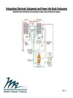
Multiple Circuit Sequencer Systems
Multiple circuit sequencer configurations are used when the total electrical load of all the controlled equipment exceeds the current
handling capacity of a single circuit, or if remote sequenced locations are required.
Power amp section must switch on last and switch off first, as shown in the figure below.
Low voltage controlled power modules
Sequencer controller
Signal
processing
section
Power amp
section
Constant “on”
outlet
Power modules
may be fed by
separate circuits
J-Box
Remote amp
Hi
Mid
Sub
Multiple circuit feeds
30 A
“Stand Alone”
M
odu
le
Low Voltage Control Wiring
120V Wiring
Stand Alone
Low Voltage
Controlled Power
Module
„ON‟
Sequence
„OFF‟
Sequence
Single circuit feed
18
Integrating Electronic Equipment and Power into Rack Enclosures © 2002-2010 Middle Atlantic Products, Inc.
Simplified Grounding Guidelines for Audio, Video and Electronic Systems
Safety Comes First: The NEC Code must be adhered to at all times, including its interpretation by the Authority Having
Jurisdiction (AHJ).
There are several meanings of the word “ground” which contributes to confusion and misunderstanding. Most commonly,
ground refers to a return path for fault and leakage current. In electrical utility power, a ground is an actual connection to soil for
the purpose of lightning diversion and dissipation, and for the purpose of keeping all exposed surfaces at the same potential as
the soil. Building safety grounds provide a return path specifically for fault and leakage currents. The safety ground for audio,
video, and other electronic systems must be connected to the building (facility) safety ground. When safety ground connections
or the neutral connection at the service entry panel are loose or corroded it will be hazardous and cause system noise.
Proper grounding reduces only ONE source of noise (common-mode). Both the primary electrical system grounds and the
signal interconnection system grounds need to be properly designed and installed to achieve a “hum and buzz free” system.
Electrical safety grounding is necessary to limit danger to the user from hazardous voltages due to lightning, power surges,
and ground faults caused by equipment failure or conductor insulation failure. Proper electrical grounding assures safety by
providing a low impedance path for “tripping” protective devices such as circuit breakers and fuses when a ground fault (short
circuit to ground) occurs. This saves lives. Bypassing or defeating a safety ground to reduce noise is illegal, violates the NEC, is
dangerous and should never be done!
Best practices dictate that equipment racks must be bonded together. Per the NEC (Article 640) or Authority Having
Jurisdiction, it is best to bond ganged racks together with paint-piercing hardware and purchase racks with pre-installed ground
studs for convenience and to ensure good conductivity.
19
Integrating Electronic Equipment and Power into Rack Enclosures © 2002-2010 Middle Atlantic Products, Inc.
Isolation Transformers (Separately Derived Systems): Benefits and Wiring Methods
Properly designed and installed shielded isolation transformers can significantly reduce AC line noise that affects AV systems. There
are two types of AC line noise: differential-mode and common-mode.
Differential-mode noise on the power line is defined as voltage appearing between the hot and neutral conductors. Isolation
transformers do not prevent differential-mode noise from passing between the primary and the secondary. The job of a power
transformer is to magnetically couple 60Hz as efficiently as possible, but frequencies up to 1kHz can couple quite well. Depending
upon the construction of the transformer, most frequencies above 1kHz are attenuated, more significantly as the frequency increases.
Common-mode noise on the power line is defined as the voltage measured equally between hot and safety ground, and neutral and
safety ground. This noise can couple into audio/video signal paths through poorly-designed safety ground systems, equipment and
cabling. Common-mode noise is capacitively coupled through the transformer while differential-mode noise is magnetically coupled
through the transformer.
Common-mode noise arising within a facility can be caused by many devices, including motors, lighting dimmers, etc. It can also be
caused by high resistance ground connections. As the length of the circuit from the isolation transformer to the equipment increases,
the chance for induced common-mode noise also increases.
When a voltage is provided by a transformer or derived from a generator or double conversion online uninterruptible power supply
(UPS), it is termed “separately derived” (NEC Article 250.30). High frequency common-mode noise can capacitively couple between
the primary and the secondary windings of a transformer. A separately derived system power isolation transformer eliminates common-
mode noise between neutral and safety ground because these are bonded together immediately after the transformer. The use of an
electrostatic (Faraday) shield, which reduces the capacitive coupling between the primary and secondary windings, provides additional
isolation at high frequencies. The shield is also very effective at suppressing fast rise time voltage spikes.
Most AV installations benefit from a dedicated shielded isolation transformer with a single ground reference point. The transformer will
be a buffer between the utility company and facility electrical system and the protected electronics systems such as AV equipment,
control electronics, dimmers and data devices.
20
Integrating Electronic Equipment and Power into Rack Enclosures © 2002-2010 Middle Atlantic Products, Inc.
Isolation Transformer Neutral-Ground Bonding Methods
All separately derived systems are required by the NEC to have a neutral-ground bond point on the secondary side of the transformer.
The location of this bond point can have a significant impact on the performance of an AV grounding system. The following diagrams
are all approved by the NEC for safety, but have varying degrees of performance for AV systems.
Not Ideal for AV Systems:
The “neutral-ground bond” in this type of wiring arrangement is at the first
circuit breaker panel after the transformer. The busbar in the circuit breaker
panel is a “combination” neutral / ground connection point, and ALL return
current (i.e. neutral, fault, and system leakage current) flows through this
busbar on its way back to the source of supply (the transformer).
This current flow causes slight voltage differences along the length of the
busbar. Since the busbar is the primary ground reference, these voltage
differences will be seen as ground voltage differences between the chassis of
interconnected equipment, and may manifest themselves as hum and buzz in
the system (through the system cable shield interconnects).
Better for AV Systems:
The “neutral-ground bond” in this type of wiring
arrangement is at the transformer. The circuit
breaker panel after the transformer contains a
separate isolated neutral busbar AND a
separate ground busbar. Return current on the
neutral busbar has no effect on the grounding
system.
MAIN PANEL
“SINGLE PHASE 120/240V”
TRANSFORMER
GROUNDING
ELECTRODE
CONDUCTOR
AS SHORT
AS POSSIBLE
INSULATORS
NEUTRAL
GROUND
TO LOADS
POWER
INPUT
MAIN GROUND
BUS
ELECTROSTATIC SHIELD
21
Integrating Electronic Equipment and Power into Rack Enclosures © 2002-2010 Middle Atlantic Products, Inc.
Isolation Transformer Neutral-Ground Bonding Methods (cont’d)
Best for AV Systems:
Commonly available single-phase transformers can have their secondary windings field-connected in one of two ways: 120/240V (as
shown in the previous 2 drawings) or 120/120V (shown below). AV systems can benefit from 120/120V because all load circuits get
their power from the SAME PHASE, thereby minimizing the effect of cross-phase leakage currents.
In a 120/120V wiring arrangement (pictured below), the neutral conducts ALL of the return current, not just the imbalance, as with a
120/240V single phase system. Since the neutral bar on a typical panel board is sized to handle the full load of only one hot leg, a
panel with double the current rating must be specified to handle the combined load of both secondary windings. The two separate
neutral conductors between the transformer and panel are also required in order to handle the full load of the separate hot legs. Note: a
200 amp panel only has a rated neutral capacity of 100 amps.
22
Integrating Electronic Equipment and Power into Rack Enclosures © 2002-2010 Middle Atlantic Products, Inc.
Electrostatic (Faraday) Shielding in Power Transformers
All transformers have capacitance between the primary and secondary windings, which allows higher frequencies of common-mode
noise to pass – as shown in the diagram above left. Utilizing an electrostatic (Faraday) shield between the windings reduces this
capacitance and provides a path for the noise to flow back to its source - as shown in the diagram above right.
Load
N-G Bond Point
Power Transformer with an Electrostatic Shield
Electrostatic
Shield
Load
Noise path
N-G Bond Point
Standard Power Transformer (Unshielded)
Inter-winding capacitance passes noise
23
Integrating Electronic Equipment and Power into Rack Enclosures © 2002-2010 Middle Atlantic Products, Inc.
K-Rated Three Phase Power Transformers
K-rated transformers are used to deal with harmonic content in three phase systems. Power conductors that feed audio and video
equipment often contain harmonics. These harmonics consist of frequencies much higher than 60Hz. Because the voltage phase
angle between phases are separated by 120 degrees, some of the 3
rd
, 9
th
, 15
th
and all odd multiples of the 3
rd
harmonic current in the
shared neutral conductor are additive. The additive currents are referred to as “triplen” harmonics. These harmonics generate
additional heat in the transformer and can cause non-K-rated transformers to overheat, reducing the life of the transformer, and
possibly causing a fire. The value used to describe how much harmonic current a transformer can handle without exceeding its
maximum temperature rise is referred to as a K-Factor Rating. K-factor values range from 1 to 50.
A K-13 transformer can accommodate twice the amount of the harmonic loading of a K-4 rated transformer, and is recommended for
normal AV systems where a three phase transformer is required.
Harmonics primarily originate in equipment such as:
a) Computers and other equipment with switch mode power supplies that do not
employ “power factor correction”
b) Electronic Ballasts
c) Motors and Controllers that use variable frequency drives
d) Most lighting dimmers
e) Power amplifiers and other equipment with DC power supplies containing
large capacitors
Some problems created by harmonic currents are:
a) Over-heated neutrals
b) Over-heated transformers
c) Malfunctioning generators
d) Burned-out motors
e) Tripped circuit breakers
Some features of K-Rated transformers are:
a) Oversized neutral, since much of the harmonic current appears on the neutral
b) Special high efficiency coil windings
c) Attenuates triplen harmonic currents from the line
d) Low impedance and temperature rise
*Note: single-phase transformers do not need a K-rating, as the harmonics pass through to the primary feeder.
K-Rated transformers do not eliminate
harmonics. They are designed to
tolerate the heating effects of
harmonics created by much of today’s
electronic equipment, which contains
switch-mode power supplies
Oversized neutral
K-Rated Three Phase Transformer
Electrostatic Shield