Expansion of Operating Limits for Permanent Magnet Motor by Current Vector Control
Bạn đang xem bản rút gọn của tài liệu. Xem và tải ngay bản đầy đủ của tài liệu tại đây (523.01 KB, 6 trang )
I
866
IEEE
TRANSACTIONS
ON
INDUSTRY
APPLICATIONS,
VOL.
26,
NO.
5,
SEPTEMBERIOCTOBER
1990
Expansion
of
Operating Limits for Permanent
Magnet Motor
by
Current Vector Control
Considering Inverter Capacity
Absfmct-
Permanent magnet (PM) motors are attracting growing at-
tention for a wide variety of industrial applications. In traction and
spindle drives, constant power operation and wide speed range are de-
sirable. With dc motor drives, these are achieved
by
the appropriate
reduction of the field current as the speed increases. In the PM mo-
tor, direct control
of
the magnet flux is not available. The air-gap flux,
however, can
be
weakened
by
the direct axis armature current. In this
operation, magnet demagnetization due to the direct axis armature reac-
tion must be prevented, because the magnet torque decreases irreversibly
if this demagnetization is very large. The current vector control method
of PM motors is examined to expand the operating limits considering
the inverter capacity. This control method is optimum in the sense
of
deriving maximum output torque within the voltage and current con-
straints. The effects of motor parameters are examined
by
the computer
simulation. The operating limits are examined considering the demag-
netization of the permanent magnet.
I. INTRODUCTION
RMANENT MAGNET (PM) motors are attracting
p"
growing attention for a wide variety of industrial appli-
cations. The maximum steady-state torque of the PM motor
depends on the continuous armature current rating. The maxi-
mum speed attainable at this torque is limited by the available
output voltage of the inverter.
In traction and spindle drives, constant power operation and
wide speed range are desirable. With dc motor drives, these
are achieved by the appropriate reduction
of
the field current
as the speed increases. In the PM motor, direct control
of
the magnet flux is not available. The air-gap flux, however,
can be weakened by the demagnetizing current in the direct
axis
[
11-[4]. This control method is called "flux-weakening.''
In this operation, magnet demagnetization due to the direct
axis armature reaction must be prevented because the magnet
torque decreases irreversibly if this demagnetization is very
large.
In this paper, the armature current control method expand-
ing the operating limits is examined under the constant inverter
capacity. The effects of motor parameters such as
d-
and q-
Paper IPCSD
90-2
1, approved by the Electric Machines Committee of the
IEEE Industry Applications Society
for
presentation at the 1989 Industry Ap-
plications Society Annual Meeting, San Diego, CA, October 1-5. Manuscript
released
for
publication March 6, 1990.
S.
Morimoto,
Y.
Takeda, and
T.
Hirasa are with the De7artment of Elec-
trical Engineering, College of Engineering, University
of
Osaka Prefecture,
4-804
Mom-Umemachi, Sakai, 591 Japan.
K.
Taniguchi is with the Department
of
Electrical Engineering, College of
Engineering,
Osaka
Institute of Technology, 5-16-1 Omiya, Asah-ku,
Osaka,
535
Japan.
IEEE Log Number
9037046.
d-axis
'd
'a
Fig. 1.
Basic vector diagram
for
PM
motor.
axis inductances, flux linkage of the permanent magnet, and
so
on are examined by computer simulation. Furthermore, the
control method and the output characteristics are examined
considering the demagnetization of the permanent magnet due
to the direct axis armature reaction.
11. BASIC EQUATIONS
OF
PM MOTOR
In the d-q coordinates which rotate synchronously with an
electrical angular velocity
w
,
the steady-state voltage equation
is expressed as follows:
d-
and q-axis components of armature current,
d-
and q-axis components
of
terminal voltage,
flux linkage of permanent magnet per-phase
(rms),
armature resistance,
d-
and q-axis components of armature self-
inductances.
=
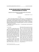
Erom
(l),
the basic vector diagram shown in Fig.
1
is ob-
tained. The
d-
and q-axis components of the armature current
are represented as
id
=
-Ia
sin0
i,
=Ia
cos0
(2)
where Ia
=
die,
I,
is the armature current per-phase (rms),
and
/3
is the leading angle of armature current from the q-axis.
The power
P
and the terminal voltage
Va
are given by
P
=
+
(Ld
-
Lq)idig}
(3)
V
a-
-
J
(W$a
+
WLdid
+
Ri,)2
+
(
-wLqiq
+
Rid)*.
(4)
0093-9994/90/09OO-0866$01
.OO
0
1990
IEEE
MORIMOTO
et
al.:
EXPANSION
OF
OPERATING
LIMITS
FOR
PERMANENT
MAGNET
MOTOR
867
To
examine the demagnetization of the permanent magnet due
to the d-axis armature reaction, the demagnetizing coefficient
C:
is
defined
as
the ratio of the
d-axis
armature reaction flux
to the permanent magnet
flux
linkage
[6];
If
E
is large and the coercivity of the magnet is not enough,
then the permanent magnet demagnetization may create a se-
rious problem and the magnet torque decrease irreversibly.
In the per-unit expression, these basic equations
are
rewrit-
ten as follows, where the armature resistance is neglected as
the
PM
motor is
used
comparatively in high speed range and
the resistance drop can also be neglected:
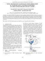
Fig.
2.
I.
-"
-
Voltage-I imit Current-limit
el
I
ipse
_ *
Increasing
swed
-
Current-limit circle and voltage-limit ellipse
for
interior
tor.
magnet
mo-
P
=
w
{Ed,
+
(1
-
p)Xdidiq}
(6)
Fig.
2
shows the current-limit circle and the voltage-limit el-
lipse in the
id-iq plane. The voltage-limit ellipse becomes
small as the speed
w
increases. The armature current vector
i(id, iq) satisfying both conditions of the current limit and the
voltage limit must be inside the current-limit circle and the
voltage-limit ellipse. For example, the available armature cur-
rent vector at
w
=
WO
is inside ABCDEF (hatched area) in
(7)
V,
=
(WE0 wxdid)2
+
(WpXdiq)*
f
=
-Xdid/EO
where
Eo =W'$,/v:
xd
=WrLdzL/v:
x,
=wrLqz:/v:, Fig.
2.
p
=
xq/xd
is the salient coefficient, and superscript
r
rep-
resents its rated value.
The salient coefficient
p
represents the saliency of the
PM
motor[6].
As
the relative permiability of a permanent magnet
is very nearly unity, the magnet space behaves like an air.
The surface magnet motor exhibits negligible saliency,
so that
p
=
1.0. On the other hand, the q-axis inductance of the
interior magnet motor exceeds the d-axis inductance; hence
p
>
1.
In
this paper, the surface magnet motor and the interior
magnet motor are examined.
III.
ARMATURE
CURRENT VECTOR CONSIDERING INVERTER
CAPACITY
Considering the inverter capacity, the armature current
I,
and the terminal voltage Vu are limited as follows:
The current limit
Ilh
is decided by the continuous armature
current rating and the available output current of the inverter.
The voltage limit
Vlim is decided by the available maximum
output voltage of the inverter. In this paper, the current and
voltage limits
are
set
as
the ratings
(Ilh
=
1.0
pu,
VI^
=
1.0
pu) for the simulation. From
(2)
and
(9),
the current-limit
circle is given by
ii
+
ii
=
I:,
IV. OPTIMUM CURRENT VECTOR CONTROL
From (6), the torque is represented as
T
=
P/w
=
(Eo
+
(1
-
p)Xdid)iq.
(13)
From this equation, the armature current vector il(id1,
iql)
producing maximum torque per current is derived as follows
[51:
(14)
id1
=
0
iql
=I,,
id1
=
-I,
sin01
iql
=
I,
cosP1,
P
#
1
where
*
(15)
-Eo
+
JE;
+
8(p
-
1)2X:Zi
4(p
-
1)xdIu
01
=sin-'
The maximum torque-per-ampere current vector trajectory is
shown in Fig.
3.
If the armature current
I,
is limited by
Ilim,
the maximum torque is obtained at point
A1
in Fig. 3. The
d-
and q-axis components of this point are derived by substituting
I,
=
Ilim in
(
14) and
(15).
Until the terminal voltage Vu
reaches its limited value Vlim at
w
=
w1,
the motor can be
accelerated by this maximum torque. This maximum speed of
the constant torque operation is given by
From (7) and
(lo), the voltage-limit ellipse is given by From (6) and (12), the armature current vector i2(id2, iq2)
producing maximum output power under the voltage-limit
condition is derived
as
follows, where the current-limit con-
(Eo
+
xdid)2
+
(pXdiq)2
=
(Vli,/w)*.
(12)
I
868
IEEE TRANSACTIONS ON INDUSTRY APPLICATIONS,
VOL.
26,
NO.
5.
SEPTEMBERIOCTOBER
1990
.
itaxiaua
Voltage-1 iaited
aaximm-output
2.
o'q
torque-per-amp
trajectory
,
J/
trajectory
P
=1.0
Voltage-1 imi
t
el
I
ipse Xd4.75
-2.01
(a)
Uax
i
mu.
torque-per-aap
.
trajectory
2.
0Iq
Voltase-
I
imi ted\
Rlxium-output Current-I imit
P
=2.0
Eo'O.
6
Xd=0.75
ellipse
A4(-EO/Xd.0)
-2.0
(b)
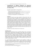
Fig.
3.
Maximum torque-per-ampere current vector trajectory
and
voltage-
limited maximum-output current vector trajectory
for
Eo
<
X,Jlirn.
(a)
Surface magnet motor
(p
=
1).
(b)
Interior magnet motor
(p
>
1).
dition is not considered,
where
I
Pfl
The current vector trajectory of the voltage-limited maximum-
output is shown in Fig.
3.
The current vector approaches the
point
A4
(id
=
-Eo/Xd,iq
=
0)
as the rotor speed increases
and reaches the current-limit circle at
w
=
w2
(point
A2
in Fig.
3).
The rotor speed
w1
is the maximum speed for the constant
torque operation with the maximum torque considering the
current limit. The rotor speed
w2
is the minimum speed for the
voltage-limited maximum-output operation. Below this speed,
the voltage-limited maximum-output operating point cannot
be reached, because the voltage-limited maximum-output tra-
jectory intersects the voltage-limit ellipse outside the current-
Lxiaua
torque-per-aap
2.07
trajectory
Yo
I
tage-1
imi ted
axiauroutput
x,4.5
ellipse
-2.01
Fig.
4.
Maximum torque-per-amp current vector trajectory and voltage-
limited maximum-output current vector trajectory
for
Eo
>
Xdlli,,,.
DC
SUPP~Y
Inverter
Fig.
5.
Scheme
of
flux-weakening control system.
limit circle. To produce the maximum output power in all
speed ranges considering the conditions of both the current
and the voltage limits, the optimum current vector is choosen
as follows.
Region
Z
(w
5
wl):
id
and
i,
are constant values given by
(14).
The current vector is fixed at
A1
in Fig.
3.
Region
ZZ
(a1
<
w
w2): id and
i,
are chosen as the cross
point of the current-limit circle and the voltage-limit ellipse.
The current vector moves from A1 to A2 along the current-
limit circle as the rotor speed increases.
Region
ZZZ
(a
5
w2):
id and
i,
are given by (17). The
current vector moves from
A2
to
A4
along the voltage-limited
maximum-output trajectory.
Region I corresponds to
Z,
=
Zli,,
Vu
<
Vlim. Region
I1 corresponds to
Z,
=
Zlim,
Vu
=
Vlim. Region I11 corre-
sponds to
I,
<
Zlirn,
Vu
=
I/lim.
If &/Xd is larger than
Zlimr
the voltage-limited maximum-output trajectory is outside the
current-limit circle (see Fig.
4).
Therefore, Region I11 does
not exist, and the output power becomes zero at
w
=
w3
(point
A3
in Fig.
4):
(19)
Fig.
5
shows the scheme of the flux-weakening control sys-
tem in which the current vector is controlled according to the
Vlim
EO
-
Xdzlim
*
w3
=
MORIMOTO
et
al.
:
EXPANSION OF OPERATING LIMITS FOR PERMANENT MA(
U2
Region
II
I
Region
111
I
0
-0.5
,;'
I
1:b
Speed
2
w
(PU)
3:O
4!i'"
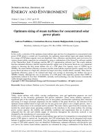
Fig.
6.
Output power characteristics for surface magnet motor.
-
with
flux
weakening;
- -
-
- - -
without
flux
weakening.
foregoing algorithm. The relationships between the current
commands
iC;,
i;,
the torque command
T
*
,
and the rotor speed
w
are preliminarily obtained by the simulation based on the
knowledge of the motor parameters. These relationships are
stored in the memory of the microprocessor as a lookup table.
The current commands are decided by the torque command
and the detected speed using the lookup table. The commands
iC;
and
i;
are transformed to the phase current commands
i;
and
i:
using the rotor angle feedback
0.
The closed-loop cur-
rent controller is responsible for controlling the
PWM
volt-
age excitation
so
that the instantaneous phase currents follow
their commanded values. The current commands are always
kept inside the voltage-limit ellipse and the current-limit cir-
cle. Therefore, the current regulators
are
not saturated in all
operating regions, and the resultant currents follow the com-
manded currents.
Fig.
6
shows the output power characteristics for the sur-
face magnet motor (nonsalient machine:
p
=
1).
The motor
parameters used in Fig.
6
are
the same in Fig. 3(a). The
terminal voltage reaches its limited value at
w
=
w1.
Below
this speed, the torque is kept constant and the output power
is proportional to the rotor speed. The output power without
the flux-weakening control
(id
=
0
control) decreases rapidly
over this speed (see the broken lines). On the other hand, the
output power with the flux-weakening control is large and kept
almost constant by controlling the
d-
and q-axis components
of the armature current according to the rotor speed (see the
solid lines). The operating limits are greatly enlarged by the
optimum current vector control.
V.
EFFECTS
OF
MOTOR
PARAMETERS
Fig.
7
shows the effects of the motor parameters such as
Eo
and Xd. If
Eo
5
XdZlim
(Xd
=
0.7,
0.8
in Fig.
7),
the
output power does not decrease at high speed. If
EO
>
XdZlim
(Xd
=
0.5,
0.6
in Fig.
7),
the output power decreases as the
rotor speed increases. In the speed range of Fig.
7
(w
5
4.0
pu), it can be seen that the output characteristics for
xd
=
0.6
is the best. The same results
are
obtained in case of the interior
magnet motor
(p
>
1).
From Fig.
7,
it has been seen that
the ideal constant power operation can be obtained with the
condition of
Eo
2
XdZlim
[7].
;NET MOTORS
869
Xd=O.
6
1.0
b
B
0.6
c
B
d
0.4
0.2
0
1.0
2.0
3.0 4.0
Speed
w
(PU)
Fig.
7.
Effects
of
motor parameters.
b
0.6
*:
0.4
0.2
1.0
U4
4
a
0.5
.O
8
L
I
J
-1.0
OO
1.0
2.0 3.0 4.0
Seed
w
(PU)
Fig.
8.
Effects
of
saliency.
Fig.
8
shows the effects of saliency. The output powers of
the different type motors are nearly the same at high speed
range
(w
>
2.0),
but the output power of the interior magnet
motor
(p
=
2
.O
or 3
.O)
is larger than that of the surface magnet
motor
(p
=
1
.O)
at low speed range because the reluctance
torque is available in the interior magnet motor. The maximum
values of the demagnetizing coefficient are about
0.8.
In some
cases, the permanent magnet is demagnetized irreversibly by
the flux-weakening control.
VI.
DEMAGNETIZATION
OF
PERMANENT
MAGNET
If the
PM
motor is controlled by the foregoing flux-
weakening control method, which uses the negative d-axis
armature current, it is very important to examine the demagne-
tization of the permanent magnet, because the magnet torque
decreases irreversibly if the demagnetization is very large.
Fig.
9
shows the equivalent d-axis magnetic circuit for the
PM
motor. The following nomenclature applies in Fig.
9:
po
permeability of air,
pr
Pu
Plm
Pla
recoil permeability
(
G!
po)
=PuIm/Arn,
where
Pu
=
pOAg/Ig,
permeance of
air gap,
=P/mlm/Am,
where
Plm
=
leakage permeance of
magnet,
=PIaIm
/A
m
,
where
pio
=
leakage permeance of ar-
mature,
I
870
IEEE TRANSACTIONS ON INDUSTRY APPLICATIONS, VOL.
26,
NO.
5.
SEPTEMBERIOCTOBER
1990
B
Air gap
B,
B,
Permanent
magnet
Armature
reaction
Fig.
9.
Equivalent d-axis magnetic circuit
for
PM
motor
B
Load
line
.=urllc
Fig.
10.
Demagnetization curve
for
rare-earth permanent magnet.
I,
magnet length,
Am
magnet area,
I,
air gap length,
A,
effective gap area,
H,
coercivity,
H,
magnetic field intensity by armature reaction.
Fig.
10
shows the demagnetization curve for a rare-earth
permanent magnet where the sign of magnetic field intensity
H
is reversed. With the permanent magnet that has a straight
demagnetization curve, such as a rare-earth permanent mag-
net, the recoil line coincides with the demagnetization curve.
Therefore, the operating point of the magnet moves along the
demagnetization curve. Using the demagnetizing coefficient
C;
defined in
(8),
the operating point
(H,,
B,)
is given as
follows:
where
U
(pU
+P/m)/Pu,
leakage factor of flux,
x
Ho,
Bo
(pu
+pl,,)/p,,
leakage factor of
MMF,
operating point at no-load,
The d-axis armature current can be safely increased until
the resultant flux density at the trailing edge of the magnet
becomes approximately zero. This safe operating condition is
represented as follows:
t
5
him.
(22)
-
:
without demagnetization-limit
___
:
E
Iim=o.a
0
'2.0
0.2
-0.5
-1.0
1.0
2.0
3.0
4.0
Speed
w
(PU)
Fig.
1 1.
Output characteristics c0nsiderir.g demagnetization limit.
From
(8)
and
(22),
the d-axis armature current considering
the demagnetization is limited as follows:
id 2
-
EOhim
/Xd
(23)
The demagnetization-limit
C;lim
is given by substituting
Bm
=
0
in
(21):
The leakage factors
U,
h
are larger than
1.0;
therefore,
Elirn
>
1.0.
If the demagnetization curve is not straight, the
demagnetization-limit
Elim
may be smaller than
1
.O.
&im
must
be carefully desided according to the permanent magnet ma-
terial and the design of magnetic circuit.
Fig.
11
shows the output characteristics considering the de-
magnetization limit. The d-axis armature current
id
is limited
according to the demagnetization limit.
As
a result, the out-
put power decreases at high speed range as the demagnetizing
limit decreases. Therefore, a magnet material that has a linear
demagnetization curve must be used for the
PM
motor if wide
speed range or constant power operation is desirable.
VII.
CONCLUSION
In this paper, the current vector control method for ex-
panding the operating limits is examined under the constant
inverter capacity. On the basis of the simulation, the following
conclusions can be obtained.
1)
The operating limits are greatly expanded by controlling
the d- and q-axis components of the armature current accord-
ing to the rotor speed.
2)
The output characteristics are affected by the parame-
ters such as
Eo
and
Xd
.
If
Eo
Xdllim,
the operating limits
become very large. When
Eo
Xdllim,
the ideal output char-
acteristics can be obtained. If
Eo
>
Xdllim,
the output power
is large in the low speed range but the wide speed range cannot
be obtained.
3)
In the interior magnet motor, in which the q-axis induc-
tance is larger than the d-axis inductance, the large output
torque can be obtained as the positive reluctance torque is
available.
MORIMOTO
et
al.:
EXPANSION
OF
OPERATING LIMITS FOR PERMANENT MA(
4)
The control method considering the demagnetization-
limit is analyzed.
If the permanent magnet has a straight de-
magnetization curve, as does a rare-earth permanent magnet,
the
PM
motor can be safely operated until the demagnetiz-
ing coefficient becomes
1.0.
If wide speed range or constant
power operation
is
desirable, the permanent magnet with a
high coercivity and a linear demagnetization curve must be
used for the
PM
motor.
REFERENCES
[l]
B. Sneyers, D. W. Novotny, and
T.
A. Lipo, “Field weakening in
buried permanent magnet ac motor drives,”
IEEE
Trans.
Ind. Appl.,
vol. IA-21, pp. 398-407, Mar./Apr. 1985.
T. Sebastian and
G.
R. Slemon, “Operating limits of inverter-driven
permanent magnet motor-drives,”
IEEE
Tins.
Ind. Appl.,
vol.
IA-
23, pp. 327-333, Mar.lApr. 1987.
T.
Jahns, “Flux-weakening regime operation of an interior permanent-
magnet synchronous motor drive,”
IEEE
Trans.
Ind.
Appl.,
vol.
IA-
B. K.
Bose, “A high-performance inverter-fed drive system of an in-
terior permanent magnet synchronous machine,”
IEEE
Trans.
Ind.
Appl.,
vol. IA-24, pp. 987-997, Nov./Dec. 1988.
T. M. Jahns,
G.
B. Kliman, and T.
W.
Neumann, “Interior permanent-
magnet synchronous motor for adjustable speed drives,”
IEEE
Trans.
Ind. Appl.,
vol. IA-22, pp. 738-747, JulylAug. 1986.
Y.
Takeda and T. Hirasa, “Current phase control methods for per-
manent magnet synchronous motors considering saliency,” in
PESC
Conf.
RE.,
Apr. 1988, pp. 409-414.
R. Schiferl and T. A. Lipo, “Power capability of salient pole permanent
magnet synchronous motors in variable speed drive applications,” in
IEEE IAS Annu. Meeting
Conf.
Re.,
1988, pp. 23-31.
[2]
[3]
23, pp. 681-689, July/Aug. 1987.
[4]
[5]
[6]
[7]
Shigeo Morimoto
was born
on
June 28, 1959. He
received the B.E. and M.E degrees from Univer-
sity of Osaka Prefecture, Japan, in 1982 and 1984,
respectively.
He joined the Mitsubishi Electric Corporation,
Tokyo, Japan, in 1984. Since 1988, he has been
a Research Associate in the Department of Electri-
cal Engineering at the University of Osaka Prefec-
ture, engaged in research
on
inverter systems and
ac servo control systems.
Mr. Morimoto is a member of the Institute of
Electrical Engineers of Japan, the Society of Instrument and Control Engi-
neers of Japan, and the Japan Society
for
Power Electronics.
;NET MOTORS
87
1
Yoji Takeda
was born in Osaka, Japan, on Novem-
ber
10,
1943 He received the B.E., M.E., and
Ph.D. degrees from the University of
Osaka
Prefec-
ture, Japan, in 1966, 1968, and 1977, respectively
In 1968, he joined the Department of Electncal
Engineering, University of
Osaka
Prefecture He is
presently an Associate Professor.
Dr.
Takeda is a member of the Institute of Elec-
trical Engineers of Japan, the Institute of Systems,
Control and Information Engineers, and the Japan
Society for Power Electronics.
Taka0 Hirasa
(M’85) was born on May 13, 1930.
He received the B.E. and Ph.D. degrees from the
University of Osaka Prefecture, Japan, in 1958 and
1965, respectively
Since 1953, he has been with the Department of
Electrical Engineenng at the University of Osaka
Prefecture, where his areas of interest are power
system stability, motor controls, and power elec-
tronics applications. Since 1976 he has been a Pro-
fessor of Electrical Engineering.
Dr. Hirasa is a member of the Institute of Elec-
trical Engineers of Japan, the Institute of Systems, Control and Information
Engineers, and the Japan Society for Power Electronics.
Katsunori Taniguchi
(M’75) was born in Na-
gasalu, Japan, on April 21, 1943. He received the
B.S.
degree in electrical engineering from Osaka In-
stitute of Technology, Osaka, Japan, and
the
M.S.
and Ph.D degree from University of Osaka Pre-
fecture, Osaka, Japan, in 1966, 1970, and 1974,
respectively.
Since 1966, he has been with the Department of
Electrical Engineering, Osaka Institute of Technol-
ogy, where he is currently a Professor. He is en-
gaged in research on PWM power conversion sys-
tem and its application to the motor control.
Dr. Taniguchi is a member of the Institute of Electrical Engineers of Japan,
the Society of Instrumentation and Control Engineers, and Japan Society for
Power Electronics.