A new caching architecture for efficient video on demand services on the internet
Bạn đang xem bản rút gọn của tài liệu. Xem và tải ngay bản đầy đủ của tài liệu tại đây (167.72 KB, 10 trang )
A New Caching Architecture for Efficient Video-on-Demand Services on the
Internet
Duc A. Tran Kien A. Hua
School of Electrical Engineering and Computer Science
University of Central Florida
Orlando, FL 32816, USA.
Email: dtran,kienhua @cs.ucf.edu
✁
✂
Abstract
We focus on the problem of enabling video-on-demand
services on the Internet. We propose a cost-effective solution called Caching Agent, an overlay architecture consisting of caching servers placed across the Internet. Unlike conventional proxies, these caching servers act as
application-layer routers and cleverly cache data passing
by. When a client’s request encounters a cache miss at the
local agent, this request may be satisfied by another nearby
agent without consuming any server bandwidth. This strategy significantly alleviates the bottleneck at the server. Furthermore, since the full content is usually obtained from
some agent instead of from the server which is usually overloaded, Caching Agent results in a better service delay in
comparison with conventional proxy schemes designed for
video on demand.
1 Introduction
Proxy servers have proved to be effective for caching
Web pages. However, that does not imply an immediate
success to video-on-demand (VoD) applications, which are
our focus in this paper. Indeed, video files are generally over
tens of million times larger than traditional web pages. As
a result, the number of video objects that can be cached in a
web proxy is very limited. The current solution is to cache
only a small (e.g., prefix, suffix or selective) portion of
each video, and let the server deliver the remaining portions
[3, 9]. To use the caching space more effectively, techniques
that enable cooperation between video proxy servers have
been proposed [1, 6]. All these partial caching schemes
help to reduce service latency; however, they do not address
the enormous demand on server since most of the data still
✄
This research is partially supported by the National Science Foundation grant ANI-0088026.
Simon Sheu
Department of Computer Science
National Tsing Hua University
Hsin-chu, Taiwan 30013, R.O.C
Email:
have to be provided by the server. To ease this problem, the
caching space reserved at a proxy would have to be considerably large, which might be prohibitively expensive for
many applications.
It is desirable to have a new video proxy scheme that
functions partial caching only, but provides the performance
benefits of whole caching (i.e., caching the entire video).
In this paper, we propose a solution called Caching Agent
to achieve this goal. In Caching Agent, video proxies, or
agents, are placed across the network to form an overlay for
routing and streaming video. This overlay can be that of
an ISP’s network or a video distribution network, which are
built on top of the Internet. Each agent plays the role of a
software router, which intercepts the data passed through,
cleverly caches them into a FIFO fix-size buffer, and appropriately routes them toward the requesting client. The use
of a FIFO buffer helps prolong the usefulness of a video
stream. In other words, subsequent clients arriving late can
join this overlay to receive the full service from the nearest
agent that still holds a prefix of the requested video in its
FIFO cache.
The advantages of the Caching Agent approach are
threefold. First, the server load is substantially reduced
since agents can also provide full services. This makes the
system scalable with a large quantity of clients. Second, our
technique is cost-effective since the required caching space
per agent is fixedly sized and a lot smaller than the video
size. With the design for RAM (Random Access Memory)
increasingly improved, the FIFO buffer can be implemented
using RAM, thus further improving the performance. Third,
a client has a good chance to be served by an agent since
there are many of them in the overlay, thus the service delay is shorter than if that client is served by the server who is
usually overloaded by many client requests. In other words,
the on-demand requirement is better achieved.
The remainder of this paper is organized as follows. In
Section 2, we introduce the Caching Agent framework and
Server Site
Client
Video Server
Video Server
Client
Client
I-Agent
R-Agent
X-Agent
X-Agent
WAN
X-Agent
X-Agent
X-Agent
X-Agent
I-Agent
I-Agent
Client
Client
Client
Client
Client
Client
Figure 1. An Architecture for VOD Systems
explain how video services are achieved. In Section 3, we
present design aspects in implementing Caching Agent. We
report our simulation study in Section 4. Finally, we conclude this paper in Section 5.
2 Agent-based Caching for Video Streaming
A typical VOD system consists of a video server (or several servers) to store video files and a number of clients
who request and receive video data from this server via a
public network or a service provider’s network. We extend this VOD system with the concept of caching agents,
thus naming our scheme Caching Agent. The agents are located across the Internet and linked according to an appropriate topology so that they form an overlay network around
the servers and user communities. The routing of video
requests and the delivery of data are tasks of the agents.
Specifically, each agent plays the role of a virtual router,
which receives a video packet, caches it according to our
proposed cache management policy, and forwards it to a
proper adjacent agent. In this new architecture, agents are
classified into three types based on their location: internal
agents (I-agents), external agents (X-agents), and root agent
(R-agents). Like a proxy server in the conventional proxy
architecture, each I-agent is proxy for a subnet of users. In
contrast, X-agents are not representative for any region of
users whereas the R-agent is placed at the server site like a
front-end proxy for the servers. An overview of the architecture is depicted in Fig. 1.
The motivation behind using the overlay architecture is
twofold. First, it has been shown to be a practical solution to
implement unicast-based multicast services on the Internet
[5] which lacks a wide deployment of IP Multicast. Second,
extensions can be easily made to the overlay to support new
needs. In this paper, we exploit it to support VOD applications. Nevertheless, the deployment of overlay nodes incurs
hardware costs and overhead associated with handling node
failures. Sharing the same insight in [5], we believe that
one-time hardware costs do not drive the total cost of the
system. In terms of overlay failures, there are two kinds of
impact: on the overlay topology and on the on-going services. Several efficient solutions [2, 7, 5] have been proposed for building fault-tolerant overlays re-configurable on
failure. Such a solution can be appropriately adopted to
maintain the Caching Agent overlay. For on-going services
that may be interrupted due to an agent failure, all the adjacent agents that have been receiving data from this failed
agent can be temporarily reconnected to the root agent to
receive the remaining data. Even though suboptimal, this
solution gives a simple and quick way to guarantee the continuity in the client playback. Since our main targets in this
paper are orthogonal to the above issues, without loss of
generality, we assume that the Caching Agent overlay has a
predefined topology and is failure-free.
We assume that a video is transmitted as a sequence of
equal-size blocks and during a time unit the network can
transmit a block. A block may contain several video frames
(e.g., I, P, or B frames in MPEG format). On receipt of these
blocks, the client is responsible for decoding and rendering
them on the screen. Agents do not have to decode data. A
request, submitted by a client to its I-agent, is forwarded
to the agent backbone to find a cache hit. If a cache hit is
found at an agent (either I-agent or X-agent), this agent will
serve the requesting client. Otherwise, the R-agent will provide the service. We provide the agent design, and service
routing and transmission in the following subsections.
2.1 Agent Cache Management
Each agent is equipped with a local storage to facilitate
caching. The caching space is organized as an array of
equally sized chunks, each used to cache data from a particular video stream currently passing through the agent. The
chunk size, which is a multiple of video block size, should
be very small compared to the video size, and as well as the
number of chunks, is chosen based on the resource availability of the agent. Let us consider an agent having a
0. When a new
number of chunks, each of size
stream arrives at agent at time ,
finds a chunk,
say chunk , to cache . The block replacement within this
chunk resembles the Interval Caching approach [4]. Every time a new data block arrives, it is copied into chunk .
This chunk can be used to service all clients requesting the
.
same video, that arrive at agent before time +
Indeed, will be used as a sliding window to hold the data
received from stream and then forward the data to the new
requesting clients. At time +
, chunk is full of data
blocks. If currently not used to provide service to any other
clients, is cleaned up and returned to the free pool. Otherwise, it continues caching as usual and old blocks will be
replaced with newly arriving blocks according to the FIFO
replacement policy.
✌
✑
✑
✑
✌
☎
☎
✆✞✝✟☎✡✠☞☛
✍✏✎ ☎
✌
☎
✑
✒✍ ✎ ✆✞✝✟☎✡✠
✍ ✎ ✆✓✝✔☎✕✠
✑
Given that an agent has a number of chunks, the chunk
replacement works as follows. We note that chunk replacement is different from block replacement done in a chunk.
A chunk replacement is invoked when a new video stream
arrives at an agent and the agent needs to find a chunk to
cache it. If there exists a free chunk, it is assigned to the
new stream. If all the chunks are currently serving some
clients, no caching is performed at the agent, i.e., the agent
just forwards the data to the next agent on the delivery path.
Otherwise, to find a victim chunk to replace, we select the
chunk that has not been used to service any downstream
client for the longest time; this victim is the chunk whose
current caching age is oldest among all non-serving chunks.
By replacing an old caching chunk with a younger one, we
widen the interval of arriving requests that can be served by
the newly cached data. We can also employ another chunk
replacement policy based on the popularity of video streams
if that is known. In this case, the victim chunk would be
the chunk that is currently caching the least popular video
but not serving any downstream clients. The decision on
which of the two chunk-replacement policies above is used
depends on the type of applications, hence we leave it as a
parameter of each agent.
2.2 Delivery Procedure
A client ✖ requests a video ✗ by sending a request to its
corresponding I-agent ✘✙☎✡✚ . This agent “broadcasts” the request in a find packet to the agent overlay. By broadcast, we
mean to apply on the overlay level only. In other words, an
agent forwards the packet to all adjacent-on-overlay agents
on the corresponding unicast paths. A duplicated packet arriving at an agent is ignored. Since the number of agents
is not large, the network load incurred by this broadcast
should not affect the network traffic severely.
Upon the first arrival of the find packet, each agent
checks if the first block of ✗ is being cached in any of its
chunks. If this condition holds, the agent stops forwarding and sends a found message on a direct unicast to ✘✛☎✜✚
to inform that client ✖ can download the video from that
chunk. If no non-root agent caches the first block, the find
will eventually go to the R-agent which also stops forwarding and sends a found to ✘✙☎✡✚ to notify.
There may be more than one agent sending a found to
✘✛☎✕✚ . ✘✛☎✕✚ selects the earliest informing agent, say ☎✜✢✤✣✦✥★✧ ,
by sending an ack message to it and sending negative-ACK
messages (nack) to the other informing agents. We pick up
the “earliest” agent to reduce the service start-up delay. The
video data will be sent from ☎ ✢✤✣✦✥★✧✩✣ on a delivery path down
to the client. This delivery path is the reversal of the path
on which the find request is sent from the client to ☎ ✢✤✣✤✥✒✧
which is also called the “serving agent” of the client. As
video blocks are sent to the client, each intermediate agent
Server
Missing
portion
Missing
portion
Missing
portion
WAN
Proxy
Server
Server
Proxy
Cached
portion
Existing
stream
Missing
portion
WAN
Cached
portion
Proxy
Proxy
Cached
portion
Client
B
Client
A
(a) Proxy Caching (non-cooperative)
Cached
portion
Client
B
Client
A
(b) Proxy Caching (cooperative)
Figure 2. Caching Agent vs.
Proxy Caching
WAN
Agent
Entire video
Client
B
Client
A
(c) Caching Agent
conventional
on the delivery path caches them into a victim chunk if there
is any available. These cached data can be used to service
subsequent requests as discussed in Section 2.1.
We note that there might be a delay between the time
☎✕✢✤✣✤✥✒✧✩✣ sends the found message to ✘✙☎✡✚ to declare itself
as a potential server and the time it receives the ack message from ✘✛☎✕✚ . Therefore, if ☎✡✢✤✣✦✥★✧ is a non-root agent, it
might have dropped the first video block from the cache by
the time it receives the permission. Hence, ☎✜✢✤✣✦✥★✧ could not
fully service client ✖ . A way to avoid this is to take into
consideration the end-to-end delay (based on the timestamp
in the find message) when a non-root agent assesses its ability to satisfy a request.
To disconnect service, client ✖ sends a quit message in
the reverse direction of the delivery path to its serving agent.
Upon receipt of this quit, each intermediate agent is pruned
off the delivery path if not currently using the data destined
for ✖ to serve any downstream client; then this agent forwards quit to the next agent on the reverse path. If an intermediate agent uses the data destined for ✖ to serve at least
a client, this agent just removes client ✖ from its delivery
schedule and does not need to forward quit to the upstream.
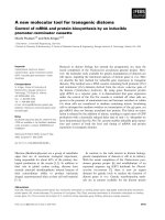
Fig. 2 gives an intuitive view of how our design is different from existing proxy caching approaches for video
streaming. The bold curves represent the data transmission
paths for the new client (client ✪ ) while the dotted ones represent the data transmission paths for an earlier client (client
☎ ). In Figure 2(a), a conventional video proxy using partial
caching must rely on the server for most part of the service.
Although cooperative proxies can be used to improve the hit
ratio as shown in Figure 2(b), the server bandwidth cost remains the same. This cost is avoided in the Caching Agent
as illustrated in Figure 2(c). By getting all the data from a
nearby agent (X-agent or I-agent) in the network, client ✪
avoids consuming server bandwidth.
One might argue that forcing all intermediate agents on a
delivery path to cache a video stream is superfluous and prefer caching at several selected agents. However, our caching
policy has its advantages. Firstly, a caching chunk becomes
empty when it is full and not used to serve any downstream
client, thus the lifetime of the data cached in a chunk is
short. As a result, caching a stream at all intermediate
agents of a delivery path does not significantly reduce the
caching space for other streams. Furthermore, this does not
introduce any significant complexity. Secondly, caching a
stream at all agents of a delivery path significantly increases
the chance for subsequent clients to hit the caches and decreases the cache seeking time.
2.3 Example
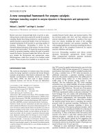
To illustrate how Caching Agent works, we give an example in Fig. 3. We assume that there is only one video
server site and that each agent has only a chunk that can
cache up to ten video data blocks. The agents are connected according to the topology in Fig. 3(a). All videos
are assumed to be longer than ten units. The label on each
link indicates the starting time of the service of a particular client. For instance, label ”0” indicates that at time
0, the server starts delivering the video to client ✖✕✫ over
the agents ✬✭☎ , ✮✯☎✭✫ , ✘✙☎✭✫ . For simplicity, we assume that
there is no service delay. That is, ✖✰✫ can make a request at
time 0 and receive the first unit of the data stream instantaneously. Fig. 3(b) illustrates the following scenario. At time
0, a node ✖ ✫ requests a video ✗ . Since no agent caches the
data, the R-agent ✬✭☎ has to allocate a new stream to serve
✖ ✫ . As the data go toward ✖ ✫ , all the agents along the way,
✬✡☎ , ✮✯☎ ✫ , ✘✛☎ ✫ , cache the data in their chunk. At time 7,
client ✖✲✱ requests the same video ✗ . Since at this time ✮✯☎ ✫
has not dropped the first video block from its chunk, it can
serve ✖ ✱ . As a result, all the agents along the path from the
serving agent ✮✯☎✜✫ to ✖ ✱ (i.e., ✮✳☎ ✱ , ✮✯☎✕✴ and ✘✙☎ ✱ ) are
asked to cache the video. At time 8, client ✖✵✴ also requests
the video ✗ . ✖✶✴ can get the service from agent ✘✙☎✜✫ since
✘✛☎✭✫ still holds the first video block. At time 10, ✮✳☎☞✫ , ✘✙☎✭✫ ,
and ✬✭☎ removes the first video block from their cache. At
time 11, ✖✸✷ asks for video ✗ , and it can receive the service
from agent ✮✯☎✕✱ which still has the first block of the video.
We note that the four clients share only one stream from
the server, yet start their own playback at their own time.
Clearly, the burden on the server bandwidth is minimal. If
proxy caching was used the server would have to create four
connections for the four clients to download the missing
data (i.e. the data not available at proxy servers). If the
server supported only one video stream at a time, then obviously, clients ✖✶✱ , ✖ ✴ and ✖✸✷ would not be served.
3 Implementation Design
We propose design aspects in implementing Caching
Agent in this section. In our Caching Agent framework,
services are achieved by a messaging mechanism among
Video
Server
C4
C2
Video
Server
0
C4
I-Agent
IA4
C2
11
7
R-Agent
RA
I-Agent
IA4
I-Agent
IA2
R-Agent
RA
X-Agent
XA1
X-Agent
XA2
X-Agent
XA3
X-Agent
XA1
I-Agent
IA1
X-Agent
XA4
I-Agent
IA3
I-Agent
IA1
0
8
C3
C1
C3
0
I-Agent
IA2
7
11
7
X-Agent
XA2
7
X-Agent
XA3
8
X-Agent
XA4
8
I-Agent
IA3
0
C1
(a) Agent Layout
(b) Streaming Tree
Figure 3. Example of how Caching Agent
works
the agents. Caching Agent classifies messages into six different packet types: REQ, FIND, FOUND, REP, DATA and
QUIT. A client ✖ requests a video by sending a REQ packet
to its I-agent ✘✙☎ ✚ , which in turn broadcasts a FIND packet
to the agent backbone to find a cache hit for the client. If
cache hit is found at an agent ☎ , ☎ will inform ✘✛☎ ✚ by
sending a FOUND packet to it. In response, ✘✛☎ ✚ replies
with a REP packet to tell whether or not ☎ is selected to
serve client ✖ . If ☎ is selected, it will transmit video data
towards client ✖ in DATA packets. To cancel the service,
✖ sends a QUIT packet to ✘✙☎✡✚ . The main task of an agent
is to receive a packet, recognize its type, and process it accordingly. Firstly, we present the details of the packet types
and necessary structures. We then present the algorithms to
deal with these packet types at each agent.
3.1 Packet Types and Data Structures
REQ: To request a video, a client node sends a REQ
packet to its local I-agent. Each REQ contains the following
information: (1) MachineID: This is the identifier of the
client node that sends this REQ packet. Each client node
has a unique identifier in its subnet. (2) ReqID: This is the
request identifier generated by the client software for each
service request. This identifier is unique within each client
node. (3) VideoID: This is the identifier of the requested
video.
FIND: Upon receipt of a REQ, if a local I-agent is unable
to serve (i.e., having a cache miss), it broadcasts a FIND
packet to the agent backbone to find a cache hit. A FIND
packet is similar to the REQ packet with an additional field
called AgentID. This field contains the identifier of the local
I-agent.
FOUND: When a FIND packet arrives at an I-agent or
X-agent ☎ that has a matching busy/hot chunk (i.e. cache
hit), ☎ sends a FOUND packet to the agent specified in the
AgentID field of the FIND packet to inform that ☎ can pro-
vide the service. That is, ☎ declares itself as a potential
serving agent. A FOUND packet is similar to the FIND
packet with an additional field called CacheAgentID containing the identifier of agent ☎ .
REP: When an I-agent ✘✙☎ receives a FOUND packet
from some potential serving agent ☎ , ✘✛☎ replies with a REP
packet containing the following information: (1) (AgentID,
MachineID, ReqID): these three fields are the same as in
the FIND packet. They identify the service request. (2)
CacheAgentID: This field specifies the potential serving
agent ☎ . (3) ACK: This can be 0 or 1. If ACK = 1, the
agent ☎ is selected to be the serving agent; it is not selected,
otherwise (ACK = 0).
DATA: This is a video data packet. A DATA packet
has the following header fields (1) ServingAgentID: This
identifies the serving agent that sends this DATA packet.
(2) SeqNum: The sequence number of the video block (3)
(AgentID, MachineID, ReqID): these three fields identify
the destination of this DATA packet.
QUIT: A client node sends this packet if it wishes to
withdraw its participation from a service session. A QUIT
contains the following information: (1) ServingAgentID:
This identifies the agent that has been serving the client
node. (2) (AgentID, MachineID, ReqID): These fields
identify a specific service to be canceled.
To support the Caching Agent activities, we maintain the
following data structures at each agent:
CACHE DIRECTORY (CacheDir): It maintains information about the current state and content of each chunk.
This directory has the following attributes: (1) ChunkID:
The identifier of the chunk. (2) VideoID: The identifier
of the video being cached in the chunk. (3) StartBlock:
The identifier of the oldest block currently in the chunk.
(4) EndBlock: The identifier of the newest block currently
in the chunk. (5) Status: The state of this chunk, which
can be either FREE, BUSY or HOT (see Fig. 1(b)). (6)
ClientCount: The number of downstream nodes that are being served by this chunk.
LOG TABLE (LogTable): It contains a log record for
each FIND packet that travels through the agent. Each log
record has the following fields: (1) ArrivalTime: This is
the time when the FIND packet first comes to the agent.
(2) (AgentID, MachineID, ReqID): These three attributes
identify the request specified in the FIND packet. This information is used to detect and discard any redundant FIND
packet arriving from a different path of the broadcast. We
recall that an agent broadcasts a FIND message upon receipt
of a request from a local client node. (3) FromAgentID:
This entry identifies the agent that sent the FIND packet
to the current agent. Afterwards, if the current agent is on
the delivery path for the corresponding request, the agent
ID specified in this field will be copied to the SinkAgentID
field of the DeliveryTable table in order to dynamically ex-
pand the delivery tree.
SERVICE TABLE (ServiceTable): This table holds
information about requests being serviced by the current
agent. A pending request is also inserted into this table
while the agent is waiting for an REP packet. If the REP has
ACK = 0, the pending request is removed from this table.
ServiceTable has the following attributes: (1) (AgentID,
MachineID, ReqID): These three fields identify a service
request. (2) ChunkID: The chunk that is being used, or will
be used to serve this request.
DELIVERY TABLE (DeliveryTable): This table identifies where to get the data from the upstream, and where
to forward the data to the downstream for a given request. This table has the following attributes: (1) (AgentID,
MachineID, ReqID): These entries identify the request. (2)
ServingAgentID: The entry identifies the serving agent of
the request. (3) SourceAgentID: The current agent receives
data packets from the agent specified in this field in order to participate in the service of the current request. (4)
SinkAgentID: The current agent forwards the data packets arriving from the upstream to the agent specified in this
field. (5) ChunkID: This entry identifies the chunk allocated for the service of this request. The chunk is used for
caching and forwarding purposes, i.e., holding data for the
next agent in the downstream.
CLIENT TABLE (ClientTable): An I-agent uses this
table to maintain information about the local requests in the
subnet, that are being served or are waiting for service. This
table has the following attributes: (1) ServingAgentID: This
entry identifies the serving agent of the request. Initially,
this is set to NULL. (2) (MachineID, ReqID): These two
values uniquely identify a specific local request.
3.2 Agent Routines
Since I-agents, X-agents, and R-agents are not equal in
functionality, they use different software algorithms. In
practice, it might be desirable to have only one type of software to be installed on any agent. This could be achieved
by installing the complete set of service routines at every
agent. The algorithm to process REQ packets is explained
as follows. A client requests a video by sending a REQ
packet to its I-agent. In response, the I-agent adds a new
entry for the client into ✖✭✹✟✺✼✻✾✽✿✍✦❀✰❁❃❂❄✹✔✻ , and checks the cache
directory ✖✭❁❅✑❇❆❈✻✾❉❊✺●❋ to see if any prefix of the requested
video is in some chunk. If yes, the I-agent pipelines video
data from this chunk to the client and adds an entry for the
client into ✌❍✻■❋❑❏✙✺✦✑✩✻✾❀✰❁❃❂❄✹✟✻ . Otherwise, the I-agent creates
a new FIND packet corresponding to the REQ request and
sends the FIND to every out-going adjacent agent.
In response to a FIND packet each agent performs a
routine illustrated in Fig. 4. Firstly, if there is already an
entry for the requesting client (specified in the FIND) in
▲◆▼✾❖
❀✰❁❃❂❄✹✟✻ , the routine ignores the FIND packet and quits.
Otherwise, a new entry is added. Afterwards, the agent
checks its ✖✭❁✙✑■❆P✻❑❉◗✺✼❋ to see if any prefix of the requested
video is in some chunk. If yes, the agent adds a new entry
for the client into ✌❘✻✾❋❑❏✛✺✦✑✩✻✾❀✰❁❃❂❄✹✔✻ and sends a new FOUND
packet back to the agent that sent the FIND packet. Otherwise, the agent forwards FIND to every out-going adjacent
agents except the one that sent the FIND packet, and adds
an entry for the client into ❉❊✻❑✹❙✺✼❏❅✻✾❋✾❚❅❀✰❁❃❂❄✹✔✻ . In the case that
an R-agent receives a FIND packet, the R-agent will always
send a FOUND back to the agent that sent the FIND to the
R-agent.
On receipt of a FOUND packet, there are the following possibilities (Fig. 5): (1) The receiving agent is the
I-agent of the requesting client: If the receiving agent
has previously received a FOUND packet (by looking at
✖✭✹❙✺✦✻✾✽✿✍✦❀✰❁❃❂❄✹✟✻ , it updates ✖✭✹✟✺✦✻■✽✿✍✦❀✕❁❅❂✩✹✟✻ and sends a new REP
packet (with ACK=0) corresponding to the FOUND to the
agent that sent FOUND to the receiving agent. If the receiving agent has not previously received any FOUND packet,
it adds a new entry for the client into ❉❊✻❑✹❙✺✼❏❅✻■❋❑❚❅❀✰❁❃❂❄✹✔✻ and
sends a REP packet with ACK=1 back to the agent that sent
FOUND to the receiving agent. (2) The receiving agent is
not the I-agent of the requesting client: The receiving agent
adds a new entry for the client into ❉❊✻❑✹✟✺●❏❅✻✾❋❑❚✙❀✕❁❅❂✩✹✟✻ and forwards the FOUND to the agent ☎ that previously sent FIND
▲◆▼✾❖
to the receiving agent. Agent ☎ is found from
❀✰❁❃❂❄✹✟✻ .
The routine on REP packets is illustrated in Fig. 6. On
receipt of a REP, if the receiving agent is not specified in
the field CacheAgentID of the REP, the receiving agent will
forward REP to the agent ☎ who previously sent FOUND to
the receiving agent. ☎ is found from ❉❊✻❑✹❙✺✼❏✙✻✾❋❑❚❅❀✰❁❃❂❄✹✟✻ . Furthermore, if ACK=0, the entry corresponding to the requesting client is removed from ❉❊✻❑✹❙✺✼❏❅✻✾❋✾❚❅❀✰❁❃❂❄✹✔✻ . Otherwise, the
receiving agent finds a chunk to cache the incoming data
that are to be sent to the requesting client. If the receiving
agent is the destination of REP, there are two possibilities:
(1) ACK = 0 (not selected to serve the client): The receiving
agent deletes the entries for the client in ✌❘✻✾❋✾❏✙✺✦✑✩✻✾❀✰❁❃❂❄✹✟✻ and
❉❊✻❑✹❙✺✼❏✙✻✾❋❑❚❅❀✰❁❃❂❄✹✟✻ . (2) ACK = 1 (selected to serve the client):
The receiving agent sends video data in DATA packets to
the agent that sent REP to the receiving agent and updates
✖✭❁✙✑■❆P✻❑❉◗✺✼❋ accordingly.
The algorithm dealing with DATA packets is simple.
When an agent receives a DATA packet, it caches the data
into the victim chunk and forwards the DATA to the next
agent based on ❉❯✻✾✹✟✺✼❏✙✻✾❋❑❚❅❀✰❁❃❂❄✹✟✻ . In response to a QUIT
packet (Fig. 7), if an agent is the I-agent of the quitting
client, the agent stops forwarding data to the client and
deletes the corresponding entry from ✖✭✹❙✺✦✻✾✽✿✍✦❀✰❁❃❂❄✹✔✻ . If the
chunk at the I-agent that has been caching data destined for
the client is in not in hot state, the I-agent then forwards the
QUIT to the adjacent agent that has been sending data to the
receiving agent. This adjacent agent is determined using
❉❊✻❑✹❙✺✼❏❅✻■❋❑❚❅❀✰❁❃❂❄✹✔✻ . If the receiving agent is also the serving
agent of the quitting client, it deletes the corresponding entry in ✌❘✻✾❋❑❏✙✺✼✑❇✻■❀✕❁❅❂✩✹✟✻ , updates ✖✭❁❅✑❇❆❈✻❑❉◗✺✼❋ by decrementing
the counter on the chunk that has been serving the client.
When this counter reaches 0, the chunk becomes BUSY, or
FREE if the start block of the chunk is greater than 0.
4 Performance Evaluation
In this section, we study the performance of the Caching
Agent architecture in comparison with the conventional
proxy architecture for video streaming. In the proxy architecture, a proxy server is employed in each subnet to cache
data that is most likely to be requested by future clients in
the subnet. Particularly, we compare Caching Agent with
the following proxy caching techniques:
1. Proxy Servers with Prefix Caching (PS/PC) [3, 8, 10]:
The caching space per proxy is divided into equal-sized
chunks. The number of chunks and their size are the same
as that of the Caching Agent approach. When delivered
from the server to a client, a prefix of the requested video is
cached at a free chunk of the corresponding proxy. If all the
chunks are filled with data, the chunk replacement is based
on LFU (Least Frequently Used) policy. PS/PC was chosen for comparison because PS/PC is a proxy scheme used
widely.
2. Proxy Servers with Interval Caching (PS/IC): The
caching space per proxy is organized as a single buffer
whose size equals the total caching size per agent in the
Caching Agent approach. Interval caching policy is used
to cache data. In the comparison to this proxy scheme, we
would like to show that a simple use of interval caching as
in PS/IC is necessary but not sufficient to make Caching
Agent outperform PS/IC.
The simulated system operated on the network borrowed
from the IBM Global Network map1 . The video server was
assumed to be located in Chicago node and at each subnet a dedicated server plays the role of a proxy server (in
the case of PS/PC and PS/IC), or an agent (in the case
of Caching Agent architecture). The bandwidth on any
link between two nodes can support 100 streams by default
(e.g., 150Mbps if video is encoded as a 1.5Mbps MPEG1 stream). We assume a discrete time model where a time
unit is called a “second”. In such a second, the network can
transmit an amount equivalent to a second of video data. By
default, an agent (in Caching Agent) or a proxy server (in
PS/PC or PS/IC) has five chunks, each having a default size
of 10 minutes of video data. Each user is willing to wait at
most five minutes. When this timer expires, the user cancels
its request.
1 />
INPUT: Packet FIND (AgentID = AID, MachineID = MID, ReqID = RID, VideoID = VID)
PARAMETER:
CurrentAID: ID of the agent running this routine
CurrentTime: arrival time of FIND
SenderAID: ID of the agent who sends FIND
ALGORITHM:
IF no entry for (AgentID = AID, MachineID = MID, ReqID = RID) exists in LogTable THEN
Add to LogTable a new entry (ArrivalTime = CurrentTime, AgentID = AID, MachineID = MID,
ReqID = RID, FromAgentID = SenderAID)
IF (ChunkID = CID, VideoID = VID, StartBlock = 0, EndBlock = n, Status = s, ClientCount = count) in CacheDir
ClientCount := count + 1; Status := HOT
Create a FOUND packet (CacheAgentID = CurrentAID, AgentID = AID, MachineID = MID, ReqID = RID)
Send FOUND back to agent SenderAID
Insert into ServiceTable a new entry (ChunkID = CID, AgentID = AID, MachineID = MID, ReqID = RID)
EXIT
IF CurrentAID is not an R-agent THEN Forward FIND to every out-going adjacent agent except SenderAID
ELSE
Create a FOUND packet (CacheAgentID = CurrentAID, AgentID = AID, MachineID = MID, ReqID = RID)
Send FOUND back to agent SenderAID
Insert into ServiceTable a new entry (ChunkID = NULL, AgentID = AID, MachineID = MID, ReqID = RID)
Add an entry (CacheAgentID = CurrentAID, AgentID = AID, MachineID = MID, ReqID = RID,
SourceAgentID = NULL, SinkAgentID = SenderAID, ChunkID = NULL) into DeliveryTable
Figure 4. Routine for FIND packets
INPUT: Packet FOUND (CacheAgentID = CacheAID, AgentID = AID, MachineID = MID, ReqID = RID)
PARAMETER:
CurrentAID: ID of the I-agent or X-agent running this routine
SenderAID: ID of the agent who sends FOUND
ALGORITHM:
Find the entry for (AgentID = AID, MachineID = MID, ReqID = RID) in LogTable
Let FromAID be the value of FromAgentID
IF (AID CurrentAID) THEN
Add (CacheAgentID = CacheAID, AgentID = AID, MachineID = MID, ReqID = RID, SourceAgentID = SenderAID,
SinkAgentID = FromAID, ChunkID = NULL) into DeliveryTable
Send FOUND to FromAID
EXIT
Find the entry for (AgentID = AID, MachineID = MID, ReqID = RID) in ClientTable
Let ServingAID be the value of ServingAgentID
IF ServingAID = NULL THEN
ServingAID := CacheAID
Create a REP packet (CacheAgentID = CacheAID, AgentID = AID, MachineID = MID, ReqID = RID, ACK=1)
Send REP to the agent SenderAID
Add (CacheAgentID = CacheAID, AgentID = AID, MachineID = MID, ReqID = RID, SourceAgentID = SenderAID,
SinkAgentID = NULL, ChunkID = NULL) into DeliveryTable
EXIT
Create a REP packet (CacheAgentID = CacheAID, AgentID = AID, MachineID = MID, ReqID = RID, ACK=0)
Send REP back to the agent SenderAID
❲
❱
Figure 5. Routine for FOUND packets
INPUT: Packet REP (CacheAgentID = CacheAID, AgentID = AID, MachineID = MID, ReqID = RID,
VideoID = VID, ACK = ack)
PARAMETER: CurrentAID: ID of the agent running this routine; SenderAID: ID of the agent that sends REP.
ALGORITHM:
Find the entry for (CacheAgentID = CacheAID, AgentID = AID, MachineID = MID, ReqID = RID) in DeliveryTable.
Let SourceAID be the value of SourceAgentID in DeliveryTable.
IF CacheAID CurrentAID THEN
IF ack = 0 THEN
Delete (CacheAgentID = CacheAID, AgentID = AID, MachineID = MID, ReqID = RID) in DeliveryTable
Forward REP to SourceAID
EXIT
ChunkID = Victim-Chunk(VID) /* find a chunk that will cache the video for the request */
Forward REP to SourceAID
EXIT
IF (CurrentAID is an R-agent) THEN
IF (ack = 0) THEN
Delete the entry for (AgentID = AID, MachineID = MID, ReqID = RID) in ServiceTable
Delete (CacheAgentID = CurrentAID, AgentID = AID, MachineID = MID, ReqID = RID) in DeliveryTable
ELSE
ChunkID = Victim-Chunk(VID) /* find a chunk that will cache the video for the request */
WHILE (VID is not completely transmitted) DO
I:=I+1 (I=0 initially)
Create a DATA packet (ServingAgentID = CurrentAID, AgentID = AID, MachineID = MID,
ReqID = RID, SeqNum = I) for the next block of data retrieved from the media archive
Send DATA to agent SenderAID
IF ChunkID NULL THEN Cache DATA into chunk ChunkID and Update CacheDir accordingly
Remove the entries for (AgentID = AID, MachineID = MID, ReqID = RID) from DeliveryTable and ServiceTable
EXIT
Find the entry for (AgentID = AID, MachineID = MID, ReqID = RID) in ServiceTable. Let CID be the value of ChunkID
IF (ack = 0) THEN
Delete the entry for (AgentID = AID, MachineID = MID, ReqID = RID) in ServiceTable
Delete the entry (CacheAgentID = CacheAID, AgentID = AID, MachineID = MID, ReqID = RID) in DeliveryTable
In the entry for ChunkID = CID in CacheDir, decrement the value of ClientCount
IF ClientCount = 0 THEN IF StartBlock = 0 THEN Status = BUSY ELSE Status = FREE
EXIT
WHILE (VID is not completely transmitted) DO
I:=I+1 (I=0 initially)
Create a DATA packet (ServingAgentID = CurrentAID, AgentID = AID, MachineID = MID,
ReqID = RID, SeqNum = I) for the next block of data in chunk CID
Send DATA to agent SenderAID
In the entry for ChunkID = CID in CacheDir, decrement the value of ClientCount
IF ClientCount = 0 THEN IF StartBlock = 0 THEN Status = BUSY ELSE Status = FREE
Remove the entries for (AgentID = AID, MachineID = MID, ReqID = RID) from DeliveryTable and ServiceTable
❲
❱
❲
❱
Figure 6. Routine for REP packets
INPUT: Packet QUIT (ServingAgentID = ServingAID, AgentID = AID, MachineID = MID, RequestID = RID)
PARAMETER: CurrentAID: ID of the agent running this routine;
ALGORITHM:
IF QUIT is from the subnet THEN
Stop forwarding data to this client
Delete the entry for this client from ClientTable
Find entry for (ServingAgentID = ServingAID, AgentID = AID, MachineID = MID, RequestID = RID) in DeliveryTable
Let CID, SourceAID be the values of ChunkID and SourceAgentID in that entry, respectively
Delete the entry for this client from DeliveryTable
IF ServingAID = CurrentAID THEN
Find the entry for (AgentID = AID, MachineID = MID, RequestID = RID) in ServiceTable.
Let CID be the value of ChunkID.
Delete that entry
Find the entry for chunk CID in CacheDir.
Decrement ClientCount associated with chunk CID in CacheDir
IF ClientCount = 0 THEN Status := BUSY
IF StartBlock 1 THEN Status := FREE
Exit
Find the entry for chunk CID in CacheDir.
IF Status = HOT THEN Exit ELSE Status = FREE and Forward QUIT to SourceAID
❳
Figure 7. Routine for QUIT packets
In each simulation run, 50,000 requests are generated
having arrival times following a Poisson distribution with
the default rate = 1.0 request per second. To model the access pattern, videos are chosen out of 50 90-minute videos
according to a Zipf-like distribution with a default skew factor = 0.7 which is typical for video-on-demand applications [4]. Our performance metrics are average service delay and system throughput. Due to the limited bandwidth in
the network, a client may have to wait a certain period until
bandwidth is available all the way from the serving agent to
the client. The average service delay is computed as the ratio between the total waiting times of all “served” requests
to the number of “served” requests. This measure illustrates
the on-demand property of service. System throughput is
computed as the ratio between the number of “served” requests to the simulation elapsed time. A higher throughput
implies a more scalable system. We report the results of our
study in the rest of this section. The study on the system
throughput is illustrated in Fig. 8, and that on the service
delay is illustrated in Fig. 9.
To study the effect under caching size, we varied the
caching size per proxy/agent by changing either the chunk
size or the number of chunks. In our study, we found that
the effect under the number of chunks is very similar to that
under the chunk size. Therefore, we only report the latter in
this paper, where the chunk size varies between 2 minutes
and 20 minutes while the number of chunks is 5. PS/PC and
PS/IC perform closely to each other while CachingAgent
exhibits a significant improvement over them. As shown
in Fig. 8, in order to achieve a throughput of 0.3 req/sec,
each proxy server of PS/PC or PS/IC needs to reserve 100
minutes of data for caching purposes while a caching agent
just requires no more than 10 minutes (10 times less). On
the other hand, if a caching agent also has 100 minutes of
caching, the CachingAgent approach achieves a throughput
of 0.85 req/sec (almost 3 times higher than that of proxy
servers approach). This substantiates our earlier assess that
proxy-based approach should have a very large caching
space in order to be efficient. CachingAgent is more advantageous since it requires a lot less caching space.
In terms of service delay (Fig. 9), CachingAgent clients
experience a shorter wait (less than 30 seconds) before the
actual service starts than PS/PC and PS/IC clients do. This
is understandable since most of the time proxy clients still
get the most of requested data from the server, which should
incur a significant delay due to a long delivery distance.
CachingAgent caches almost everywhere that data travel
through, hence the chance for a client to get the requested
data from a close caching agent is very high. Consequently,
the service delay is very short compared to that of the proxybased techniques.
To study the effect of request rate, we set the request rate
to different values between 0.2 req/sec and 2.0 req/sec in
❩
❨
each simulation run. The number of requests is kept the
same and equals 50,000 requests. As more requests arrive
to the system simultaneously the number of requests served
decreases until reaching a bottom number. At that bottom
line (rate 1.4 req/sec), in any technique, most clients who
are admitted to the service can get the requested data on demand (i.e., service delay is zero). This is because the number of served requests is so small that the network bandwidth is available for all of them. However, before that,
CachingAgent clients do not have to incur such a long delay as in the proxy-based schemes (Fig. 9). In terms of
throughput (Fig. 8), PS/PC and PS/IC stall as the request
rate increases while CachingAgent continues to scale with
new arriving requests. When the requests arrive sparsely,
all techniques perform equally. The gap between them becomes larger as the network traffic becomes more loaded
with many more requests. This property reflects the high
scalability of the CachingAgent approach.
We modeled the effect of network bandwidth by varying
the inter-node link bandwidth from 50 concurrently supported streams to 150 concurrently supported streams. In
all cases, CachingAgent provides service to clients almost
instantaneously (less than 10 second wait), while with the
same network bandwidth, PS/PC and PS/IC requires clients
to wait about 50 seconds on average, which is 5 times longer
(Fig. 9). In terms of system throughput (Fig. 8), PS/IC
is slightly better than PS/PC while CachingAgent outperforms them by a sharp margin (2.5-3.0 times). That the
bandwidth utilization of CachingAgent is better than that of
PS/PC and PS/IC can be explained in two ways. First, the
server bandwidth is very demanding in PS/PC and PS/IC
since most data have to be delivered by the server. Second, the in-network bandwidth in PS/PC and PS/IC is very
bursting with data sent on long edge-to-edge distances to
clients. CachingAgent does not have those problems. As
a result, for example, the network requires a bandwidth of
150 streams per link (or 225Mbps in the case of MPEG-1)
in order for PS/PC or PS/IC to reach the throughput of 0.4
req/sec. Impressively, CachingAgent reaches 0.6 req/sec
throughput with a bandwidth of just 50 streams per link (or
75Mbps in the case of MPEG-1), which exhibits a 300%
enhancement.
5 Conclusions
We introduced in this paper a new concept in proxy
caching called Caching Agent. In existing proxy schemes,
in the case where a cache is hit, the rest of data is still
provided by server. In our approach, when a cache is hit,
the entire video will be sent to the requesting client without consuming any server bandwidth. The novelty here is
that Caching Agent does not require more caching space to
achieve that benefit.
Effect on Throughput
Effect on Throughput
1
0.7
0.6
0.5
0.4
0.3
0.2
CachingAgent
Proxy w/ Interval Caching
Proxy w/ Prefix Caching
0.1
2
4
6
8
10
12
14
16
0.8
System Throughput (request/second)
System Throughput (request/second)
System Throughput (request/second)
1.2
0.8
0.9
CachingAgent
Proxy w/ Interval Caching
Proxy w/ Prefix Caching
0.9
0
Effect on Throughput
1.4
1
0.8
0.6
0.4
0.2
18
0
20
0.7
0.6
0.5
0.4
0.3
0.2
CachingAgent
Proxy w/ Interval Caching
Proxy w/ Prefix Caching
0.1
0
0.2
0.4
Chunk Size (minute)
0.6
0.8
1
1.2
1.4
1.6
1.8
2
50
60
70
Request Rate (request/second)
80
90
100
110
120
130
140
150
140
150
Network Bandwidth (stream)
Figure 8. Effect on System Throughput.
Effect on Service Delay
Effect on Service Delay
90
Effect on Service Delay
80
CachingAgent
Proxy w/ Interval Caching
Proxy w/ Prefix Caching
80
70
CachingAgent
Proxy w/ Interval Caching
Proxy w/ Prefix Caching
70
60
50
40
30
20
60
50
40
30
20
2
4
6
8
10
12
Chunk Size (minute)
14
16
18
20
0
50
40
30
CachingAgent
Proxy w/ Interval Caching
Proxy w/ Prefix Caching
20
10
10
10
0
Average Service Delay (second)
Average Service Delay (second)
Average Service Delay (second)
60
70
0.2
0.4
0.6
0.8
1
1.2
1.4
1.6
1.8
2
Request Rate (request/second)
0
50
60
70
80
90
100
110
120
130
Network Bandwidth (stream)
Figure 9. Effect on Service Delay.
Caching Agent consists of caching proxies across the
network, and interconnects them to form an agent overlay.
Agents are not just proxies as in the conventional proxy
schemes, but also play the role of application-layer routers.
To the best of our knowledge, Caching Agent is the first to
integrate both caching and routing functionalities into the
proxy design.
We provided simulation results to demonstrate the efficiency of this approach in comparison with conventional
proxy-based techniques, namely PS/PC and PS/IC. The results indicate that Caching Agent with the caching space
10 times less than that of PS/PC and PS/IC provides a better system throughput. When using the same cache size,
Caching Agent outperforms the other two techniques by 3
times. This is achieved with the additional benefit of significantly better service latency.
In practice, the Caching Agent technique can be used in
conjunction with conventional proxies. In this hybrid environment, the proxies can focus on caching non-video objects, and leave videos to the caching agents. Such a service
network will be able to deliver both video and non-video
services in the most efficient way.
References
[1] S. Acharya and B. Smith. Middleman: A video caching
proxy server. In Proc. IEEE NOSSDAV, 2000.
[2] P. Francis. Yallcast: Extending the internet multicast architecture. In ., September 1999.
[3] S. Gruber, J. Rexford, and A. Basso. Protocol considerations
for a prefix-caching proxy for multimedia streams. In Proc.
of the 9th International WWW Conference, 2000.
[4] K. A. Hua, D. A. Tran, and R. Villafane. Caching multicast protocol for on-demand video delivery. In Proc. of the
ACM/SPIE Conference on Multimedia Computing and Networking, pages 2–13, San Jose, USA, January 2000.
[5] J. Jannotti, D. K. Gifford, and K. L. Johnson. Overcast:
Reliable multicasting with an overlay network. In USENIX
Symposium on Operating System Design and Implementation, San Diego, CA, October 2000.
[6] Y. W. Park, K. H. Baek, and K. D. Chung. Reducing network
traffic using two-layered cache servers for continuous media
on the internet. In Proc. of the IEEE Int’l Conf. on Computer
Software and Applications, pages 389–394, 2000.
[7] D. Pendakaris and S. Shi. ALMI: An application level multicast infrastructure. In USENIX Symposium on Internet Technologies and Systems, Sanfrancisco, CA, March 26-28 2001.
[8] S. Sen, D. Towsley, Z.-L. Zhang, and J. K. Dey. Optimal
multicast smoothing of streaming video over an internetwork. In Proc. of IEEE INFOCOM ’99, 1999.
[9] K.-L. Wu, P. S. Yu, and J. L. Wolf. Segment-based proxy
caching of multimedia streams. In Proc. of the 10th International WWW Conference, Hong Kong, 2001.
[10] Z.-L. Zhang, Y. Wang, D. H. C. Du, and D. Su. Video staging: A proxy-server-based approach to end-to-end video delivery over wide-area networks. IEEE/ACM Transactions on
Networking, 8(4), August 2000.