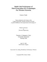
Structure enhancements of pifa for 3G mobile devices
Bạn đang xem bản rút gọn của tài liệu. Xem và tải ngay bản đầy đủ của tài liệu tại đây (340.6 KB, 4 trang )
ISSN 1859-1531 - THE UNIVERSITY OF DANANG, JOURNAL OF SCIENCE AND TECHNOLOGY, NO. 12(85).2014, VOL. 1
35
STRUCTURE ENHANCEMENTS OF PIFA FOR 3G MOBILE DEVICES
Tran Thi Huong*, Nguyen Thanh Hang**
The University of Danang, University of Science and Technology;
*
, **
Key words - 3G device; monopole antenna; L antenna; inverted F
antenna; compact antenna.
1. Introduction
Nowadays, portable devices become more and more
popular with people in the world. They are very useful in
communicating and receiving information. The demand for
mobile devices is accelerated with small size, thin and light
weight as well as convenience. In view of satisfying the
above demand, it is necessary to miniaturize its
components. Especially, the antenna size must be
miniaturized to put the entire antennas into the devices.
Many studies and suggestions of typical antenna
structures for portable devices have been published. D.
Bonefacic [1] proposed a design for a micro-strip antenna
that works on central frequency of 2 GHz and has very
small size (30×12.9×5 mm3); however, the bandwidth of
the proposed antenna is too narrow (26 MHz). Y. Kim [2]
proposed a folded loop antenna system for new future
handsets. K. Skrivervik [3] proposed an antenna with
smaller size (23×14×5 mm3) which can be applied for the
3G mobile devices. N. Q. Dinh [4] proposed a method to
miniaturize antenna structure for the 3G mobile device
(23×14×5 mm3) and then [5] the optimum design of PIFA
for the 3G mobile device with the size (21×14.5×4 mm3)
and the bandwidth (272 MHz).
In this paper, the authors use Ansoft HFSS to analyze
PIFA antenna placed on a metallic plane that represents for
a mobile device with surveyed bandwidth from 1.8 GHz to
2.3 GHz (cover 3G band: 1.9 GHz - 2.17 GHz). Therefore,
it is possible to adapt suitable method of miniaturized of
antenna structure and design a compact antenna
21×14.5×3 mm3, whose sizes are smaller than antennas in
the reference [5]. However, its height is only 3 mm but its
bandwidth and other technical parameters are still ensured
and it is possible for this antenna structure to place into
mobile devices.
Besides, in order to match antenna input impedance with
the feeder and to ensure its bandwidth must be wide enough
to cover the 3G band of Vietnam, the proposed antenna
structure is optimized. Finally, the antenna parameters such
as input impedance, VSWR and peak gain are calculated to
validate the applicability of the proposed antenna in a wide
band of 1.8 GHz – 2.3 GHz for 3G devices.
2. The Proposed Antenna Atructure
2.1. The Monopole, L, F Antenna Structure
2.1.1. The monopole antenna
Consider the standard monopole antenna structure, in
practical, monopole antenna’s length satisfies a quarter
wavelength. With the central frequency f = 2 GHz and the
speed of light c = 3.108 m/s, a quarter wavelength is
37.5 mm. It means that its length equals 37.5 mm. Due to
the limited ground plane size in the stimulation, antenna’s
length was modified by l = 33 mm. The overall dimension
of the antenna has been determined with w = 1 mm (width)
and t = 0.1 mm (thickness) placed on a metallic plane
(copper) (80×40×0.1 mm3).
Figure 1a. Monopole antenna
VSWR of the monopole antenna
2
1.9
1.8
1.7
VSWR
Abstract - The paper presents the monopole antenna’s structure,
L antenna’s structure, F antenna’s structure and shows
developments toward antenna’s structure enhancement. Thus, the
paper presents a method to enhance the structure of planar
inverted F antenna (PIFA) by meandering and folding techniques
for the monopole antenna placed on FR4 dielectric. The proposed
PIFA antenna has a compact size (21×14.5×3 mm3). In addition,
this antenna offers enough wide bandwidth 380 MHz (VSWR ≤ 2),
which covers 3G band. The authors use the simulation program
HFSS of Ansoft to compute the antenna parameters such as input
impedance, VSWR, bandwidth and the peak gain. The results from
stimulation program show the enhancement of PIFA’s structure to
verify its applicability for the 3G devices.
1.6
1.5
1.4
1.3
1.2
1.8
1.85
1.9
1.95
2
2.05
Frequency (GHz)
2.1
2.15
2.2
Figure 1b. VSWR of the monopole antenna
As can be seen from Figure 1b, the bandwidth of
monopole antenna is 230 MHz (from 1.89 GHz to
2.12 GHz) and VSWR ≤ 2; however, antenna’s size is so
long. Next, to decrease the length of this antenna, it is
folded into L antenna.
2.1.2. The L antenna
Consider the L antena with l1 = 28 mm (lenghth), l2 =
5 mm, w = 1 mm (width) and t = 0.1 mm (thickness) placed
on a metallic plane (copper) (80×40×0.1 mm3).
36
Tran Thi Huong, Nguyen Thanh Hang
As can be seen from Figure 3b, the bandwidth of F
antenna is 250 MHz (from 1.88 GHz to 2.13 GHz), VSWR
≤ 2 and F antenna size is smaller than the monopole
antenna and L antenna above.
2.2. Main Requirements of Antenna for 3G Mobile
Devices
When design an antenna for the mobile device should
take the working frequency bandwidth and the requirement
on antenna compact size into account. Normally, the 3G
mobile devices have the length, width and thickness of
110 mm, 60 mm and 12 mm, respectively. Currently, the
3G mobile system of Vietnam works on frequencies from
1.9 GHz to 2.17 GHz. Thus, the design antenna for 3G
mobile devices has to ensure the requirements on compact
size, working bandwidth and several following parameters:
Figure 2a. L antenna
VSWR of the L antenna
2
1.9
1.8
VSWR
1.7
1.6
The antenna size must be small enough to be placed
in a mobile device, its height is less than 5 mm, its length
and its width are less than 40 mm.
1.5
1.4
1.3
1.2
1.8
1.85
1.9
1.95
2
2.05
Frequency (GHz)
2.1
2.15
2.2
1 ≤ VSWR ≤ 2.
Figure 2b. VSWR of the L antenna
As can be seen from Figure 2b, the bandwidth of L
antenna is 250 MHz (from 1.88 GHz to 2.13 GHz), VSWR
≤ 2 and L antenna size is smaller than previous monopole
antenna. Next, this antenna is folded into F antenna to
decrease the length.
2.1.3. The F antenna
Consider the F antenna with l1 = 26.5 mm (lenghth), l2
= 6 mm, l3 = 4 mm và l4 = 16 mm, w = 1 mm (width) and t
= 0.1 mm (thickness) placed on a metallic plane (copper)
(80×40×0.1 mm3).
Figure 3a. F antenna
VSWR of the F antenna
2
1.9
1.8
VSWR
1.7
1.6
1.5
1.4
1.3
1.2
1.8
1.85
1.9
1.95
2
2.05
Frequency (GHz)
2.1
The input impedance of the antenna can reach 50 Ω
at the central frequency (to match perfectly with the
feeder).
2.15
2.2
Figure 3b. VSWR and input impedance of the F antenna
The bandwidth of the antenna is large enough:
≥ 10%, ≥ 200 MHz.
2.3. A Method of Miniaturized Antenna Structure
Consider the Inverted F antenna placed on a metallic
plane (using copper), with length L (70 mm) and width W
(40 mm), that presents for a mobile device.
In order to miniaturize size of the initial inverted
antenna, it is possible to apply bending, folding and slotting
methods and apply dielectric substance FR4 to solid its
structure. Furthermore, so as to ensure the antenna input
impedance, it is needed to change current in the antenna by
varying the distance between the feeding point and the
connection point and adding U, L shape strip-lines. These
strip-lines will change the current distribution on the
antenna, this in turn will change the antenna input
impedance matching with the feeder. Moreover, the
optimized antenna expands bandwidth and ensures more
compact size.
2.4. The Proposed Antenna Structure
Antenna is fixed on a FR4 dielectric plate (ε = 4.4,
tanδ = 0.02). The size of the FR4 dielectric plane is
40×14.5×3 mm3. The whole antenna ad FR4 dielectric
plate are placed at the above of the metallic plane
measuring 70×40×0.1 mm3 (Figure 4a).
Antenna associated with the metallic plane in 2 points
such as the feeding point and the grounding point (the
connection point to the metallic plane) (Figure 4b). This
antenna consists of copper strip-lines of width w2 (1 mm),
thickness (0.1 mm). The overall dimension of the antenna
has been determined with w3 = 21 mm (length), w1 =
14.5 mm (width) and h = 3 mm (height). A gap between
the feeding point and the grounding point is l5 = 8.2 mm.
Except for the strip-lines are connected to the metallic
plane, other strip-lines are fixed on the dielectric plate and
parallel to the ground. The size of the proposed antenna
ISSN 1859-1531 - THE UNIVERSITY OF DANANG, JOURNAL OF SCIENCE AND TECHNOLOGY, NO. 12(85).2014, VOL. 1
elements is shown in Table 1. The proposed has L shapes
which are formed by strip-lines l1×l2; l6×l7 and l9×l10 and U
shape with the parameters of and l4×s.
VSWR of PIFA after enhancement
2
37
Input impedance of PIFA after enhancement
80
1.9
1.8
60
1.7
40
Z (Ohm)
VSWR
1.6
1.5
20
1.4
0
1.3
1.2
-20
re(Z)
im(Z)
1.1
1
1.8
2
2.2
Frequency (GHz)
-40
1.8
2
2.2
Frequency (GHz)
Figure 5. VSWR and input impedence
of the Inverted F antenna after enhancement
(4a)
Peak gain of the Inverted F antenna after enhancement
4.5
Peak Gain (dB)
4
3.5
(4b)
Figure 4. Inverted F antenna placed on a metallic plane
Table 1. The size of the Inverted F antenna after optimization (mm)
Parameters
l3
l4
l5
l6
l7
l8
l9
l10
Values
14.2
12.5
8.2
9.8
10.5
3
7.6
4.8
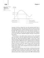
3. Simulated Results of the Proposed Antenna structure
Simulated results in the input impedance and VSWR of
the proposed antenna are shown in Figure 5. The antenna
input impedance can reach approximately 37 Ω at the
resonant frequency of 2.04 GHz. The proposed antenna
bandwidth is 380 MHz (from 1.83 GHz to 2.21 GHz) (18
% compared with the central frequency), VSWR ≤ 2.
Therefore, the proposed antenna bandwidth covers the
bandwidth for 3G devices (270 MHz). The results show
that the proposed antenna structure has the widest
bandwidth compared with the former designs.
The peak gain of the antenna within the surveyed
bandwidth is shown in Figure 6. From the figure, the
antenna gain is relatively equal and is greater than 3.6 dB
in the whole working bandwidth of the 3G device.
Simulated results show that the proposed antenna structure
can be applied to antennas for 3G mobile devices.
1.85
1.9
1.95
2
2.05
2.1
Frequency (GHz)
2.15
2.2
2.25
2.3
Figure 6. Peak gain of the inverted F antenna after enhancement
4. Results of Selecting Some Size Parameters of Antenna
VSWR of the Inverted F antenna after changing l10
2
VSWR
Values
70
40
3
1.4
14.5
21
10.7
6.8
1.5
l10 = 2.8 mm
l10 = 4.8 mm
l10 = 6.8 mm
1
1.8
1.85
1.9
1.95
2
2.05
2.1
2.15
2.2
Frequency (GHz)
VSWR of the Inverted F antenna after changing L
2.25
2.3
2.25
2.3
2
VSWR
Parameters
L
W
h
s
w1
w3
l1
l2
3
1.8
1.5
L = 60 mm
L = 70 mm
L = 80 mm
1
1.8
1.85
1.9
1.95
2
2.05
2.1
Frequency (GHz)
2.15
2.2
Figure 7. VSWR of the inverted F antenna after changing l10 and L
As can be seen from Figure 7, when changing l10 by
2.8 mm, 4.8 mm and 6.8 mm, respectively; When l10 is
6.8 mm, although VSWR ≤ 2, the bandwidth does not
cover 3G band. When l10 is 2.8 mm, VSWR ≤ 2 but the
resonant frequency is far from 2 GHz. Thus, it is necessary
to select parameter l10 = 4.8 mm because this ensures
covering the 3G band (VSWR ≤ 2). In practical, the ground
plane size is extremely large. Nevertheless, it is essential to
38
Tran Thi Huong, Nguyen Thanh Hang
miniaturize the ground plane to put it into the mobile
device. When changing L (the length of ground plane) by
60 mm, 70 mm and 80 mm, respectively; When L is
80 mm, the bandwidth does not cover 3G band despite
VSWR ≤ 2. When L is 60 mm, VSWR ≤ 2 but the resonant
frequency is far from 2 GHz. Therefore, it is necessary to
select parameter L = 70 mm because this ensures covering
the 3G band (VSWR ≤ 2).
5. Simulated Result in Comparison
In the reference [5], the proposed antenna has antenna
size (21×14.5×4 mm3); the bandwidth (272 MHz), the
ground plane size (80×40×0.1 mm3).
Figure 8 is VSWR of the PIFA in the reference [5] and
VSWR of the proposed antenna in this paper. As can be
shown, VSWR of the PIFA after enhancement in this paper
is larger than the one in the reference [5] and covers the 3G
band in Vietnam, 380 MHz and 272 MHz, respectively.
VSWR of PIFA in the reference [5] and this paper
2
1.9
1.8
1.7
VSWR
1.6
1.5
1.4
1.3
1.2
1.1
1
1.8
VSWR of PIFA in the reference [5]
VSWR of PIFA in this paper
1.85
1.9
1.95
2
2.05
2.1
Frequency (GHz)
2.15
2.2
2.25
2.3
6. Conclusion
This paper proposed an antenna structure for 3G
devices by using planar inverted F antenna. Some achieved
results are:
Compact antenna structure (21×14.5×3 mm3).
Relatively wide bandwidth 380 MHz (18 %, VSWR
≤ 2), covers the 3G mobile bandwidth of Vietnam.
Smaller ground plane (70×40×0.1 mm3).
Gain is relatively equal and is greater than 3.6 dBi
in the whole bandwidth of the 3G mobile device.
In the future, the authors continue to propose methods
of miniaturized the antenna structure to reduce the antenna
thickness while ensuring the bandwidth requirements and
other technical parameters.
REFERENCES
[1] D. Bonefacic, J. Bartolic, “Small antennas: Miniaturization
Techniques and Applications”, ATKAFF 53(1), 20-30, 2012.
[2] Y. Kim, H. Morishita, Y. Koyanagi, K. Fujimoto, “A folded Loop
Antenna System for handsets Developed and Based on the advanced
Design Concept”, IEICE Trans. Commun., vol.E84-B, no.9,
pp.2468-2475, Sept.2001.
[3] K. Skrivervik, J. F Zurcher, O. Staub and J. R. Mosig, “PCS antenna
design: The Challenge of Miniatureization”, IEEE Antennas and
Propagation Magazine, Vol.43, No.4, Aug., 2001.
[4] H. Q. Anh, N. Q. Dinh, D. Q. Trinh, “A method to miniaturize
antenna structure for the 3G mobile device”, The 2013 International
Conference on Advanced Technologies for Communications
(ATC’13), pp.191-194, Oct. 16-18, 2013.
[5] H. Q. Anh, N. Q. Dinh, “The Optimum Design of PIFA for the 3G
mobile device”, The institute of electronics, Informatin and
Communication
Engineers,
Vietnam-Japan
International
Symposium on Antennas and Propagation, 2014.
Figure 8. VSWR of the Inverted F antenna in the reference [5]
and in this paper
(The Board of Editors received the paper on 15/05/2014, its review was completed on 15/06/2014)