Solid index versus impression for transferring the position of implants in mandibular total edentulous arches a clinical study on trueness
Bạn đang xem bản rút gọn của tài liệu. Xem và tải ngay bản đầy đủ của tài liệu tại đây (317.02 KB, 7 trang )
International Journal of Advanced Engineering Research and
Science (IJAERS)
Peer-Reviewed Journal
ISSN: 2349-6495(P) | 2456-1908(O)
Vol-8, Issue-8; Aug, 2021
Journal Home Page Available: />Article DOI: />
Solid Index versus Impression for transferring the Position
of implants in Mandibular total Edentulous Arches: A
Clinical study on trueness
Ana Larisse Carneiro Pereira1, Henrique Vieira Melo Segundo2, Maria de Fátima
Trindade Pinto Campos3, Míria Rafaelli Souza Curinga4, Ana Clara Soares Paiva Tơrres5,
Adriana da Fonte Porto Carreiro6,*
1DDS,
MSc, PhD student, Department of Dentistry, Federal University of Rio Grande do Norte (UFRN), Natal, RN, Brazil.
student, Department of Dentistry, Federal University of Rio Grande do Norte (UFRN), Natal, RN, Brazil.
3Collaborating Professora, Department of Dentistry, Federal University of Rio Grande do Norte (UFRN), Natal, RN, Brazil.
4DDS, MSc student, Department of Dentistry, Federal University of Rio Grande do Norte (UFRN), Natal, RN, Brazil.
5Professora, Department of Dentistry, State University of Rio Grande do Norte (UERN), Caicó, RN, Brazil.
6Professora Titular, Department of Dentistry, Federal University of Rio Grande do Norte (UFRN), Natal, RN, Brazil.
*Corresponding author
2Graduation
Received:28 Jun 2021;
Received in revised form: 14 Jul 2021;
Accepted: 25 Jul 2021;
Available online: 06 Aug 2021
©2021 The Author(s). Published by AI
Publication. This is an open access article
under the CC BY license
( />Keywords— splinting, direct
edentulous, dental abutments.
I.
technique,
Abstract— To evaluate the trueness of two techniques for transferring the
position of implants, with respect to the angles and distances between
them, in completely edentulous arches rehabilitated with 3 and 4 implants.
All patients were subjected to 2 impressions techniques: solid index (SI)
and conventional impression using the open tray (MC) technique. The cast
models were digitized by a laboratory scanner, and the generated STL
files were imported into engineering software to measure the axes of the
coordinates of the implants and the distances between the implants. The
Wilcoxon test was used to identify the differences between the SI and MC
groups (p<0.05). The Spearman correlation coefficient was applied to
identify the correlation between the coordinate axes and the distances
between the implants (p<0.05). When comparing the SI and MC groups,
a significant difference was observed in the x-axis of implant #1, for the
arches with 3 and 4 implants (p<0.05). As for the distances, a significant
difference was observed between implants 1-2 in the arches with 4
implants (p<0.05). No correlation was identified between the two
dependent variables. The SI, as well as the MC, must be developed to
obtain a passive adjustment framework.
INTRODUCTION
The passive adjustment of implant-supported fixed
total prostheses is a determining factor for their long-term
success.1-4 Biological and mechanical complications, such
as progressive marginal bone loss (peri-implantitis),
increase or accumulation of biofilm (mucositis), loosening
of the abutment screw, fatigue fractures in the prosthetic
components5,6 or the implant, and loss of osseointegration,
www.ijaers.com
,may contribute to the inadequate adjustment of the metallic
infrastructure with the abutments or implant, to varying
extents.2,4
The impression techniques and materials,4,7
impression copings, presence or absence of splinting, as
well as the splint material and the number and angulations
of the implants4,8 are factors that affect the transfer precision
of the position of the implants to the mold and later to the
Page | 1
Ana Larisse Carneiro Pereira et al.
International Journal of Advanced Engineering Research and Science, 8(8)-2021
plaster model.4,9 This model, which is used for waxing the
metal framework, may still be influenced by the operator's
experience, plaster handling, and mold casting technique.10
In this context, several impressions techniques
have been used for the construction of working models to
provide a more precise clinical adjustment of the metal
framework. The methods of immobilization of the copings,
either by splinting with dental floss followed by acrylic
resin,3,9,10-12 addition silicone,3 interocclusal registration
materials,3,12 type II plaster,12 or methods involving rigid
materials such as titanium bars9 and solder index previously
projected in 3D on a digitized reference model, 13 produce
molds that are more accurate than those obtained by
techniques without splinting. Methods for capturing the
position of the implants with the solid index proved to be
superior to conventional (impression) and digital
methods.13-15
Numerous in vitro studies have evaluated the
influence of impression techniques on the transfer precision
of multiple implants,3,9,10-12 as well as the accuracy and/or
precision of digital versus conventional impressions from
the axes of the three-dimensional plane.16-18 However, to our
knowledge, studies comparing the clinical data between the
two techniques for obtaining the implant positions, using
the same splinting material and abutment levels, to evaluate
the axes on a three-dimensional plane, the distance between
the implants, while comparing arches with four and three
implants, have not been reported in the literature. In this
cross-sectional clinical study, we proposed to evaluate the
accuracy of two techniques for transferring the position of
implants, regarding the angle and distance between the
implants in total edentulous arches rehabilitated with four
and three implants. The null hypothesis is that there is no
difference between the solid index (SI) and the transfer
impression of the position of the implants in the total
edentulous arches rehabilitated with four and three implants
respectively.
of 44 µm and a standard deviation of 17 µm for the
technique with splinting and an average of 89 µm and
standard deviation of 60 µm for the technique without
splitting. A two-tailed hypothesis test with a significance
level of 5% and power of 80% resulted in a sample size of
32 implants. Considering the loss of follow-up, the sample
size was increased by 20%, resulting in 52 implants. Thus,
in total, 61 implants were evaluated for the two dependent
variables in this study.
After clinical and radiographic evaluation of the
implants, all patients underwent two techniques of obtaining
the implant positions: SI (solid index) and conventional
impression using the open tray (MC) technique, which was
performed by a single operator (Fig. 1).
To make the models corresponding to the two
techniques, prior to insertion in the mouth, the copings
(Neodent; Straumann) were wrapped with self-curing
acrylic resin (GC Pattern resin, GC Corporation, Tokyo,
Japan)19 After polymerization of the resin, the copings were
screwed onto the abutments with a torque of 10 Ncm
(manufacturer's instruction). Then, the copings were
splinted with metallic fragments (tips/drills for dental use)
and acrylic resin was used to fix them in place.
At this time, after the resin’s polymerization
reaction, the copings were unscrewed to obtain the SI
models, and then removed from the oral cavity to fix the
analogs (Neodent, São Paulo-SP, Brazil) in the copings.
This resin pattern was immersed in plaster type IV
(Dentsply, Vila Gertrudes, São Paulo, Brazil),13 and after
crystallization, the copings were unscrewed from the model.
This cross-sectional study was carried out at the
Dentistry Department of the Federal University of Rio
Grande do Norte (UFRN) and was approved by the
institution's Ethics and Research Committee (CEP-UFRN)
under protocol number 3.673.666. It included 10 and 7
patients with four and three implants, respectively, and
cases of implant loss were excluded from the study.
To obtain the MC plaster models, a plastic tray was
used to transfer the impression of the implant positions. An
access window was created to release the abutments in the
mouth, and then it was loaded with dense addition silicone
(Express XT, 3M, São Paulo, Brazil). The copings were
wrapped with low-viscosity addition silicone (Express XT,
3M, São Paulo, Brazil) and, in sequence, the tray loaded
with the dense impression material was positioned in the
mouth. After the initial setting reaction of the material, the
copings were unscrewed and the tray/coping set was
removed from the oral cavity. The coping analogs were
placed in the mold obtained, in which the space
corresponding to the rim was hollowed out with artificial
gingiva (Zhermack, Moema, São Paulo, Brazil) and the
other anatomical structures were recorded with type IV
plaster (Dentsply, Vila Gertrudes, São Paulo, Brazil).
The sample size was obtained from a previous
study on the precision of different techniques for
transferring implant positions. The results of the study by
Papaspyridakos et al. (2011)18 for the total 3D
displacements of the axes (x, y, and z) obtained an average
All physical models (MC and SI) were scanned
with a laboratory scanner (Zirkozahn® S600 ARTI Scan)
by the same operator. For this, scan bodies for abutments
(Neodent; Straumann) were screwed over the existing
analogs in the models and torqued at 10 Ncm
II.
MATERIALS AND METHODS
www.ijaers.com
Page | 2
Ana Larisse Carneiro Pereira et al.
International Journal of Advanced Engineering Research and Science, 8(8)-2021
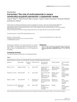
Fig. 1: Clinical sequence for performing the evaluated techniques. Index solid: (1) Impression copings positioned on
abutments, (2) Copings splinted with metallic fragments, (3) Copings unscrewed and removed from the oral cavity to fix the
analogs, (4) Resin pattern immersed in plaster type IV, (5) Removal of the plastic matrix, (6) Copings unscrewed from the
model. Conventional impression using the open tray technique: (1) Impression copings positioned on abutments, (2) Copings
splinted with metallic fragments, (3) Plastic tray loaded with dense addition silicone and the copings wrapped with lowviscosity addition silicone, (4) Tray/coping set was removed the oral cavity and the coping analogs placed in the mold, (5)
Mold, (6) Cast model.
(manufacturer's instructions). Standard Tessellation
Language (STL) files were stored in the scanner software
used for the analysis.
Codes regarding the implant positions were
standardized for the two dependent variables in this study:
For cases rehabilitated with four implants, the following
were considered: (1) posterior right, (2) anterior right, (3)
anterior left, and (4) posterior left, and for cases with three
implants, (1) posterior right, (2) median, and (3) left
posterior. Thereafter, six distances (1-2, 2-3, 3-4, 1-4, 1-3,
and 2-4) were measured for cases of four implants and three
distances for cases with three implants (1 -2, 2-3, and 1-3).
In both cases, the three axes of the coordinates (x, y, and z)
of the implants were evaluated accordingly.
Thereafter, the STL files of the digitized physical
models were imported into the GOM Inspect software
(GOM GmbH, Germany). Initially, these were overlapped
using a three-point alignment, followed by a better fit.16 In
view of the absence of a digital table in the software, the SI
model was used to standardize the insertion axis of the
models to be evaluated. Therefore, the MC models (real
www.ijaers.com
elements) were superimposed on the SI (nominal elements),
and for this, the scan body inputs corresponding to positions
1 and 4 in the cases with four implants and one and three for
the cases with three implants were determined as the most
suitable planes for the alignment of the files.
Subsequently, cylinders were designed for each
scan body and a coordinate system was defined to extract
the values corresponding to the x, y, and z axes of each
implant, and the end of the upper centroid of each scan body
was used to trace the measurement lines between the
implants at pre-established distances.
The measurements were performed three times by
the same operator (H.V.M.S.), and then checked by a
second independent appraiser (A.L.C.P.), at an interval of 3
days, and an average of the measurements was included for
data analysis. The data were analyzed using statistical
software (IBM SPSS Statistics, v22.0; IBM Corp). The
descriptive analysis was based on data presented as median
(x̅) and quartiles 25 (Q25) and 75 (Q75). The Wilcoxon nonparametric test was used to verify the statistical difference
between the SI and MC groups, as well as between the
Page | 3
Ana Larisse Carneiro Pereira et al.
International Journal of Advanced Engineering Research and Science, 8(8)-2021
rehabilitated arches with four and three implants, assuming
a significance of p<0.05. The Spearman correlation
coefficient was applied to identify the correlation between
the coordinate axes and the distances between the implants
for cases with four and three implants (p<0.05).
III.
RESULTS
To assess the reliability of the data, the interclass
correlation coefficient was applied for each axis (x, y, and
z) and distances between the implants were calculated
accordingly (Chart 1).
Charts 1: Interclass Correlation Coefficient.
SI
MC
Distances
1,000
1,000
Axis x
0,999
0,999
Axis y
0,995
0,994
Axis z
0,655
0,997
A total of 40 and 21 implants for the rehabilitated
arches with four and three implants, respectively, were
evaluated for the coordinate axes (x, y and z), totaling 61
for both the groups.
When analyzing the values corresponding to the xaxis of the arches with four implants (Table 1), a statistically
significant difference for implant #1 was observed (right
posterior implant), when comparing the SI group with MC
(p<0.05). However, in the y and z axes, no statistically
significant differences were observed for any of the implant
positions in the arch (p<0.05). For the arches rehabilitated
with three implants (Table 2), no statistically significant
differences were identified for the y and z axes of the two
groups, whereas for the x-axis, differences were observed
for implant #1 and in the total median value (p <0.05).
Sixty and 21 distances between the implants were
evaluated, respectively. For the rehabilitated arches with
four and three implants, 60 and 21 distances between the
implants were evaluated, totaling 81 distances for the two
groups. When observing the distances measured for the
cases with four implants (Table 3), the value of the total
median of the MC group was greater than that of the SI, with
a statistically significant difference (p<0.05). For the arches
rehabilitated with three implants (Table 4), there was no
statistically significant difference for each distance and the
total value per group (p<0.05).
No correlations were observed (Supplementary
Material) in either case (four and three implants) between
the axes and distances for the implants in the SI and MC
groups.
www.ijaers.com
IV.
DISCUSSION
Based on the results, our null hypothesis was
rejected. This cross-sectional clinical study analyzed the
accuracy of two techniques for transferring the implant
positions, regarding the angle and distance between them in
total edentulous arches rehabilitated with four and three
implants. The impression for transferring the implant
positions using the open tray technique (group MC) did not
accurately capture the x-axis of implant #1, for cases with
four and three implants, when compared to the SI group, as
well as the distances between the implants for cases with
four implants. No correlations were observed between the
two groups for the distances and axes in cases with four and
three implants.
The clinical and laboratory phases, necessary for
the making of the plaster model, which are used for the
closure, casting, and pressing of the implant-supported
fixed total prosthesis, can affect the accuracy of transferring
the orientation of the implants to the plaster due to
movement of the implants and impression copings. The
splinting of these is seen as a solution to minimize such
movements, with a view to stabilizing them under the
tightening torque to the analog of the copings that will be
positioned in the mold, thus reducing the rotational freedom
of the copings within the impression material.9 In addition,
the sequence of unscrewing the copings to remove the
impression tray from the oral cavity can also cause minimal
movements and influence the accuracy of the plaster
model.20
Although splinting techniques have shown
excellent results over the years, contrary opinions have been
reported in the literature. Some problems can affect the
splinting techniques, such as the fracture of the splinting
material with copings,21 because of the polymerization
contraction of the acrylic resin, which is the most commonly
used material. The solution would be to section the splint
and then reconnect it with a small amount of the same
material, after a specific time interval, as evidenced by a
previous study,22 which showed that 80% of the
polymerization shrinkage occurred in the first 17 minutes.
The standardization of the two techniques of
impression from splintering with metallic fragments made
excellent results possible, once the evaluated groups
presented minimal differences. Previous studies have
evaluated the use of metal bars to immobilize copings.
Shankar & Doddamani (2020),9 showed that the
immobilization methods using the direct technique with
metallic splinting, followed by welding in the mouth,
produced the most accurate molds, in comparison to the
direct technique of splinting with dental floss and acrylic
resin and direct technique without splinting.
Page | 4
Ana Larisse Carneiro Pereira et al.
International Journal of Advanced Engineering Research and Science, 8(8)-2021
Table 1: Median values (Q25/Q75) of the axes of the coordinates of the implants for cases with four implants.
IMP
x
n
y
SI
1
10
2
10
3
10
4
10
All
40
p
MC
5,81100
4,73800
2,75800/11,80350
3,31050/10,29250
3,07500
3,66600
1,87750/6,99800
1,84400/6,75350
3,61500
3,64300
1,43500/6,99200
2,03750/7,85300
0,868
0,210
4,12800
4,63100
3,00875/9,74825
1,86525/10,02725
3,86400
4,53300
2,32050/8,05700
2,16100/8,30400
0,006*
0,646
0,051
SI
z
p
MC
7,93600
7,11300
4,77400/10,55000
4,52950/11,20500
6,32800
6,69000
4,64750/10,56200
3,15500/10,74800
6,31500
5,38500
3,05200/10,35050
3,48400/10,00300
5,14350
4,10900
2,96450/9,36075
1,76050/7,62925
6,32800
6,69000
4,02550/9,70350
3,41650/10,59450
SI
0,653
0,906
0,981
0,333
0,906
p
MC
80,09800
79,35400
75,47750/83,15600
72,85100/82,82850
79,74900
80,00700
77,48200/83,93850
76,90500/85,30400
80,57000
81,62200
76,70550/83,97300
76,40800/85,41700
81,95000
82,79900
73,11700/84,10250
73,47250/85,30500
80,56800
80,24200
76,65900/83,50250
75,80750/85,03200
0,246
0,795
0,943
0,508
0,638
Q25: Quartile 25; Q75: Quartile 75; IMP: implant; 1: right posterior implant; 2: right anterior implant; 3: left anterior implant; 4: left posterior implant; SI: solid index; MC: conventional
impression using the open tray technique.
Table 2: Median values (Q25/Q75) of the axes of the coordinates of the implants for cases with three implants.
x
IMP
y
SI
MC
6,410
3,341-15,082
5,482-17,494
4,773
6,424
3,075-10,003
3,666-11,579
3,303
3,643
All
7,936
2,620-8,085
4,738
6,424
21
4,707-14,169
4,773
3,216-10,368
p
MC
81,349
79,354
69,061-85,184
66,564-83,288
79,749
80,007
77,619-83,804
76,571-82,014
80,570
85,025
73,741-86,719
75,727-85,355
80,570
80,242
74,936-84,431
76,023-85,123
0,612
3,311-11,231
0,091
6,690
0,866
3,075-10,033
3,321-8,130
5,935
3,966
0,091
0,866
2,824-6,340
3,456-7,486
5,935
6,690
1,000
0,741
0,006*
2,922-9,463
SI
6,855
0,176
1,027-7,882
p
MC
0,499
7
3
SI
0,028*
7
2
p
8,190
7
1
z
n
4,395-7,373
3,416-9,550
0,092
Q25: Quartile 25; Q75: Quartile 75; IMP: implant; 1: right posterior implant; 2: median implant; 3: left posterior implant; SI: solid index; MC: conventional impression using the open tray
technique.
Table 3: Distances between implants for cases with four
implants (Median - Q25/Q75).
Distances
n
SI
MC
p
1-2
10
13,52500
92,6850/16,19500
13,43100
9,44300/16,67100
0,022*
2-3
10
15,93800
14,13000/18,93550
16,13900
12,7400/18,83950
0,653
3-4
10
10,97000
9,6965/29,36550
11,16500
9,52300/29,30950
1-4
10
31,52700
30,44100/32,78675
1-3
10
2-4
10
Distances
n
SI
MC
p
1-2
7
17,128
15,903 – 28,419
17,106
16,462 – 28,435
0,058
0,136
2-3
7
16,521
15,753-16,817
16,779
16,361-17,102
0,091
31,68150
30339,25/32743,50
0,386
1-3
7
16,654
15,038-19,043
16,630
15,130-18,959
0,866
24,79850
22,67625/26,97425
24,84900
22,91575/26,17350
0,241
23,93600
21,41950/27,42500
23,95250
21,61425/27,04450
All
21
29,874
27,982-30,298
29,841
29,093-30,296
0,176
0,445
19,04300
18,95900
0,003*
12,88750/27,52800
13,10850/27,39950
25
75
Q : Quartile 25; Q : Quartile 75; 1: right posterior implant; 2: right anterior implant;
3: left anterior implant; 4: left posterior implant; SI: solid index; MC: conventional
impression using the open tray technique.
All
60
www.ijaers.com
Table 4: Distances between implants for cases with three
implants (Median - Q25/Q75).
Q25: Quartile 25; Q75: Quartile 75; 1: right posterior implant; 2: median implant; 3:
left posterior implant; SI: solid index; MC: conventional impression using the open
tray technique.
Page | 5
Ana Larisse Carneiro Pereira et al.
International Journal of Advanced Engineering Research and Science, 8(8)-2021
Del Acqua et al. (2010)23 showed that the working model
made from the splinting of copings with metal bars can be
the most accurate, in view of the stiffness of the metal in
withstanding the distortion forces. Although the authors
carried out splinting with metal bars without the use of
acrylic resin, as was done in the present study, the fragments
were joined to the copings with a small amount of resin at
the ends, just enough to keep them stabilized, freeing them
from possible failures that may be associated with the
section and joining method, as well as the polymerization
reaction of the resin.
When evaluating the coordinate axes (x, y, and z),
a statistically significant difference for the x-axis of implant
#1 in the rehabilitated arches with four and three implants
was observed. This difference in the x-axis was reported in
previous studies that evaluated impressions performed with
and without splinting.18,24,25 Papaspyridakos et al. (2011),18
also showed that when evaluating the effect of implant
position, it was observed that the x-axis of the posterior
implants in the mandible, when the impression was obtained
by splinting, presented the greatest deviation, followed by
the z and y axes. In view of these previous findings, which
are in agreement with the results of this study, another study
also pointed out that changes in the x-axis, which
corresponds to the horizontal plane, would indicate the
construction of smaller metallic infrastructures, that is, with
a probable vertical marginal mismatch, or posterior
inclination of the implants towards the palate or floor. 26
Therefore, the use of the SI model is even more appropriate
than the MC model for the manufacture of metallic
infrastructures.
The transfer technique from direct impression did
not accurately capture the distances between the implants
for the arches with four implants, when compared to the
solid index. For the arches with three implants, the
impression technique did not influence the results. Studies
that evaluated the distances between implants, comparing
splinting techniques or conventional impression methods,
were unknown by the authors of this study. Rech-Ortega et
al. (2019),27 compared a conventional technique
(elastomeric impression material) and a digital one, based
on a master model with six implant analogs. The authors
concluded that in clinical situations with more than three
implants, the conventional method was more accurate than
the digital method, while for cases with four implants, the
digital method was the most suitable. Therefore, we justify
our results for the cases with three and four implants in
terms of the distances between the implants. The
statistically significant differences found in the distance
between the right posterior implant and the right anterior
implant (#1-2) for cases with four implants reflects the
changes found in the right posterior implant (#1) on the xaxis for the MC group.
www.ijaers.com
The distribution of the implants preserving the
maintenance area of the polygon supporting the future
prosthesis,28 contributed to the absence of correlation
between the coordinate axes and the distances between the
implants, for the arches rehabilitated with four and three
implants. Although we are not aware of studies that
correlate the number of implants with axes and distances
(the opposite also applies), we emphasize that through a
negative correlation, that is, as the axes increase, the
distance decreases; if the plaster model that presented if this
result was used to design a metallic infrastructure, it would
probably present a visible vertical and/or horizontal
marginal mismatch.
In view of the results, the present study showed
that when comparing two techniques for transferring the
position of the implants, the plaster model obtained by
conventional impression using the open tray technique
should be used to obtain information about the soft tissues.
However, a solid index must also be developed to obtain
information regarding the passive metal framework.
Additionally, we compared two numbers of implants, four
and three, showing that a reduction in the number of
implants made the rehabilitation process more accessible to
the population, owing to the reduction in the final cost of
treatment.
The limitations of this study included the absence
of other splinting materials, impression techniques, and
types of implants. Future research should be conducted to
include greater numbers of dependent variables and provide
clinical responses to simplify the dental treatment.
V.
CONCLUSION
The fabrication of the plaster model through MC
using the open tray technique, compared to that of the SI,
presented difficulties in capturing the x-axis for cases with
four and three implants, but did not exhibit significant
differences for the y and z axes. The number of implants
influenced the record of the distances, showing that there
was no difference between the MC and SI groups for the
arches with three implants; however, it did not influence the
correlation of the axes with the distances. Therefore,
considering the conventional workflow, in addition to the
MC plaster model, which provided soft tissue details that
are necessary for the laboratory-based steps in the design of
the metal framework and veneering the prosthesis, a solid
index must be recorded to obtain sufficient details for
designing the passive metal framework.
ACKNOWLEDGMENTS
CAPES - Coordination for the Improvement of Higher
Education Personnel (N°88887.531281/2020-00).
Page | 6
Ana Larisse Carneiro Pereira et al.
International Journal of Advanced Engineering Research and Science, 8(8)-2021
REFERENCES
[1] Jemt T, Book K. Prosthesis misfit and marginal bone loss in
edentulous patients. Int J Oral Maxillofac Implants
1996;11:620-625.
[2] Sahin S, Cehreli MC. The significance of passive framework
fit in implant prosthodontics: current status. Implant Dent
2001;10:85–92.
[3] Buzayan M, Baig MR, Yunus N. Evaluation of accuracy of
complete-arch-multiple-unit abutment-level dental implant
impressions using different impression and splinting
materials. Int J Oral Maxillofac Implants 2013;28:1512-20.
[4] Richi MW, Kurtulmus-Yilmaz S, Ozan O. Comparison of
the accuracy of different impression procedures in case of
multiple and angulated implants: accuracy of impressions in
multiple and angulated implantes. Head Face Med
2020;16:9.
[5] Gherlone E, Capparé P, Vinci R, Ferrini F, Gastaldi G,
Crespi R. Conventional versus digital impressions for “Allon-Four” restorations. Int J Oral Maxillofac Implants
2016;31:324-30.
[6] Woo H-W, Cho S-A, Lee C-H, Lee K-B, Cho J-H, Lee D-H.
Precision of the milled full-arch framework fabricated using
pre-sintered soft alloy: A pilot study. J Adv Prosthodont
2018;10:128-131.
[7] Wee AG. Comparison of impression materials for direct
multi-implant impressions. J Prosthet Dent 2000;83:323–31.
[8] Ma J, Rubenstein JE. Complete arch implant impression
technique. J Prosthet Dent 2012;107:405–10.
[9] Shankar SD, Doddamani S. To evaluate and compare the
accuracy of definitive casts using various splinting methods
on implant level impressions in All-on-Four treatment: An
in vitro study. J Indian Prosthodont Soc 2020;20:193-201.
[10] Ribeiro P, Herrero-Climent M, Díaz-Castro C, Ríos-Santos
JV, Padrós R, Mur JG et al. Accuracy of implant casts
generated with conventional and digital impressions-an in
vitro study. Int J Environ Res Public Health 2018;15:1599.
[11] Elshenawy EA, Alam-Eldein AM, Elfatah FAA. Cast
accuracy obtained from different impression techniques at
different implant angulations (in vitro study). Int J Implant
Dent 2018;20:9.
[12] Lee S-J, Cho S-B. Accuracy of five implant impression
technique: effect of splinting materials and methods. J Adv
Prosthodont 2011;3:177-85.
[13] Mangano FG, Bonacina M, Mandelli F, Marchiori F. Solid
index versus intraoral scanners in the full-arch implant
impression: in vitro trueness evaluation. BRM Res Notes
2020;13:504.
[14] Schmidt A, Billig J-W, Schlenz MA, Wöstmann B. A new
3D-method to assess the inter implant dimensions in
patients-a pilot study. J Clin Exp Dent 2020;12:187-192.
[15] Mandelli F, Zaetta A, Cucchi A, Mangano FG. Solid index
impression protocol: a hybrid workflow for high accuracy
and passive fit of full-arch implant-supported restorations.
Int J Comput Dent 2020;23:161-181.
[16] Alikhasi M, Siadat H, Nasirpour A, Hasanzade M. Threedimensional accuracy of digital impression versus
conventional method: effect of implant angulation and
connection type. Int J Dent 2018;4:3761750.
www.ijaers.com
[17] Kim KR, Seo KY, Kim S. Conventional open-tray
impression versus intraoral digital scan for implant-level
complete-arch impression. J Prosthet Dent 2019;122:543549.
[18] Revilla-Ln M, Gonzalez-Martin Ĩ, Pérez López J,
Sánchez-Rubio JL, Özcan M. Position accuracy of implant
analogs on 3D printed polymer versus conventional dental
stone casts measured using a coordinate measuring machine.
J Prosthodont 2018;27:560-567.
[19] Papaspyridakos P, Benic G, Hogsett VL, White GS, Lal K,
Gallucci GO. Accuracy of implant casts generated with
splinted and non-splinted impression techniques for
edentulous patiets: an optical scanning study. Clin Oral
Implants Res 2012;23:676-681.
[20] Nealon FH. Acrylic restorations by the operative
nonpressure procedure. J Prosthet Dent 1952;2:513-27.
[21] Pujari M, Garg P, Prithviraj DR. Evaluation of the accuracy
of casts of multiple internal connection implant prosthesis
obtained from different impression materials and techniques:
An in vitro study. J Oral Implantol 2014;40:137-45.
[22] Moreira AH, Rodrigues NF, Pinho AC, Fonseca JC, Vilaỗa
JL. Accuracy comparison of implant impression techniques:
A systematic review. Clin Implant Dent Relat Res
2015;17:751-64.
[23] Martínez-Rus F, García C, Santamaría A, Ưzcan M, Pradíes
G. Accuracy of definitive casts using 4 implant-level
impression techniques in a scenario of a multi-implant
system with different implant angulations and sub-gingival
alignment levels. Implant Dent 2013;22:268-76.
[24] Del Acqua MA, Chavez AM, Castanharo SM, Compagnoni
MA, Mollo Fde A Jr. The effect of splint material rigidity in
implant impression techniques. Int J Oral Maxillofac
Implants 2010;25:1153-8.
[25] Hariharan R, Shankar C, Rajan M, Baig MR, Azhagarasan
NS. Evaluation of accuracy of multiple implant impressions
using various splinting materials. Int J Oral Maxillofac
Implants 2010;25:38-44.
[26] Vigolo P, Fonzi F, Majzoub Z, Cordioli G. An evaluation of
impression techniques for multiple internal connection
implant prostheses. J Prosthet Dent 2004;92:470-6.
[27] Tan MY, Yee SHX, Wong KM, Tan KBC. Comparison of
three-dimensional accuracy of digital and conventional
implant impressions: effect of interimplant distance in a
edentulous arch. Int J Oral Maxillofac Implants
2019;34:366-380.
[28] Rech-Ortega C, Fernández-Estevan L, Solá-Ruíz M-F,
Angustín-Panadero R, Labaig-Rueda C. Comparative in
vitro study of the accuracy of impression techniques for
dental implants: Direct technique with an elastomeric
impression material versus intraoral scanner. Med Oral
Patol Oral Cir Bucal 2019;24:89-95.
[29] Skalak R. Biomechnical considerations in osseointegrated
prostheses. J Prosthet Dent 1983;49:843-8.
Page | 7