Refinery Process Air Emissions ppt
Bạn đang xem bản rút gọn của tài liệu. Xem và tải ngay bản đầy đủ của tài liệu tại đây (272.16 KB, 10 trang )
Refinery Process Air Emissions
The most significant air emission sources in oil refineries are catalytic or thermal cracking units, catalytic reformer
units, sulfur recovery plants, storage vessels, fluid coking units wastewater streams, cooling towers, equipment
leaks, blowdown systems, vacuum distillation units, steam boilers, process furnaces, process heaters,
compressor engines, barge or ship loading and gasoline loading racks specifically located at petroleum refineries.
Table 1 identifies the air pollutants from these air emission sources and summarizes US EPA publication AP-42
estimates of the uncontrolled emissions from these oil refinery air emission sources. It should be noted that in
many cases these refinery air emissions have already been controlled in order to meet specific US or overseas air
emission regulations.
Table 1: Significant Refinery Air Emission Sources, Air Pollutants And Emission Factors*
Refinery Process Air Pollutant Emission Factor**
Catalytic Cracking
(Fluid Bed)
Particulates 242
Carbon Monoxide 13,700
Sulfur Dioxide 493
Nitrogen Oxides 71
Hydrocarbons 220
Aldehydes 19
Ammonia 54
Catalytic Cracking
(Moving Bed)
Particulates 17
Carbon Monoxide 3,800
Sulfur Dioxide 60
Nitrogen Oxides 5
Hydrocarbons 87
Aldehydes 12
Ammonia 6
Catalytic Reforming Hydrocarbons 25
Inorganic Chlorine 4,450
Sulfur Recovery Plant Sulfur Dioxide 359 lbs/ton sulfur recovered
Reduced Sulfur
(H
2
S, CS
2,
COS)
0.65 lbs/ton sulfur recovered
10/25/12 Ref inery Process Air Emissions
www.mcilv ainecompany .com/brochures/ref inery _process.htm
Storage Vessels Hydrocarbons No single emission factor
Fluid Coking Particulates 523
Wastewater Streams Hydrocarbons 0.097
Cooling Towers Hydrocarbons 0.0048
Equipment Leaks Hydrocarbons 0.034
Blowdown System Hydrocarbons 580
Vacuum Distillation Hydrocarbons 50
Steam Boiler, Process
Furnace or Process
Heater (Below 100
Million Btu/hr capacity)
Particulates 10 lbs/1,000 gallon #6 fuel oil
Nitrogen Oxides 55 lbs/1,000 gallon #6 fuel oil
Carbon Monoxide 5 lbs/1,000 gallon #6 fuel oil
Sulfur Oxides 157 x sulfur percentage in
fuel/1,000 gallon #6 fuel oil
Steam Boiler, Process
Furnace or Process
Heater (Below 100
Million Btu/hr capacity)
Particulates 2 lbs/1,000 gallon distillate oil
Nitrogen Oxides 20 lbs/1,000 gallon distillate oil
Carbon Monoxide 5 lbs/1,000 gallon distillate oil
Sulfur Oxides 142 x sulfur percentage in
fuel/1,000 gallon distillate oil
Steam Boiler, Process
Furnace or Process
Heater (Above 100
Million Btu/hr capacity)
Particulates 2 lbs/1,000 gallon #2 fuel oil
Nitrogen Oxides 24 lbs/1,000 gallon #2 fuel oil
Carbon Monoxide 5 lbs/1,000 gallon #2 fuel oil
Sulfur Oxides 157 x sulfur percentage in
fuel/1,000 gallon #2 fuel oil
Compressor Engine
(Reciprocating)
Hydrocarbons 1.4 lbs/1000 cubic feet gas fuel
Carbon Monoxide 0.43 lbs/1000 cubic feet gas fuel
Nitrogen Oxides 3.4 lbs/1000 cubic feet gas fuel
Sulfur Oxides 2 x sulfur percentage in fuel/1000
cubic feet gas fuel
Compressor Engine (Gas
Turbine)
Hydrocarbons 0.02 lbs/1000 cubic feet gas fuel
Carbon Monoxide 0.12 lbs/1000 cubic feet gas fuel
10/25/12 Ref inery Process Air Emissions
3/10www.mcilv ainecompany .com/brochures/ref inery _process.htm
Nitrogen Oxides 0.3 lbs/1000 cubic feet gas fuel
Sulfur Oxides 2 x sulfur percentage in fuel
gas/1000 cubic feet gas fuel
Vessel Loading (Barge) Hydrocarbons 3.4 lbs/1,000 gallons transferred
Vessel Loading (Ship) Hydrocarbons 1.8 lbs/1,000 gallons transferred
Gasoline Rack Loading Hydrocarbons 995 lbs/1,000 gallons transferred
* Uncontrolled air emissions from US EPA Document AP-42
** Expressed as lbs/1,000 bbl fresh feed unless otherwise specified
Catalytic or thermal cracking units are a major source of seven different air pollutants (particulates, carbon
monoxide, sulfur dioxide, nitrogen oxides, hydrocarbons, aldehydes and ammonia) in an oil refinery. Steam
boilers are a major source of two to four different air pollutants (particulates, nitrogen oxides, carbon monoxide
and sulfur oxides) in an oil refinery, depending upon the type of fuel burned in them. Catalytic reforming units are
a major source of two different air pollutants (hydrocarbons and inorganic chlorine) in an oil refinery. Sulfur
recovery plants are also a major source of two air pollutants (sulfur dioxide and reduced sulfur compounds) in a
refinery. All other processing operations (storage vessels, fluid coking, wastewater streams, cooling towers,
equipment leaks, blowdown systems, vacuum distillation, barge or ship loading and gasoline rack loading) are the
source of only one major air pollutant at an oil refinery. All of the above mentioned are hydrocarbon emission
sources with the exception of fluid coking, which is a particulate emission source.
Major sources of particulate air emissions in an oil refinery are catalytic or thermal cracking units, fluid coking
units, steam boilers, process furnaces, and process heaters (if the latter three are burning liquid fuel). Major oil
refinery carbon monoxide emission sources are catalytic crackers, steam boilers, process furnaces and process
heaters. Major sulfur dioxide air emission sources in an oil refinery are catalytic or thermal cracking units, sulfur
recovery plants, steam boilers, process furnaces, process heaters and compressor engines (if the latter four are
burning high sulfur gaseous or liquid fuel).
Major oil refinery nitrogen oxides emission sources are catalytic or thermal cracking units, steam boilers, process
furnaces, process heaters and compressor engines. Major sources of hydrocarbon air emissions in an oil refinery
are catalytic or thermal cracking units, catalytic reforming units, storage vessels, wastewater streams, cooling
towers, equipment leaks, blowdown systems, vacuum distillation units, compressor engines, barge or ship
loading and gasoline rack loading. Major oil refinery aldehydes and ammonia air emission sources are catalytic or
thermal crackers.
The major source of inorganic chlorine (primarily hydrochloric acid) air emissions in an oil refinery is catalytic
reforming units. The major oil refinery air emission source of reduced sulfur compounds is sulfur recovery plants.
Catalytic Cracking
Initially the crude oil entering a refinery is distilled at atmospheric pressure to produce six fractions; naphtha,
gasoline, distillate, gas oil, lighter ends and reduced crude. The gas oil is further treated by catalytic cracking to
break down its long chain hydrocarbons into lower boiling point components. The resulting lower boiling point
components can then be used by the refinery for gasoline and distillate fuel production.
Catalytic cracking units in an oil refinery use a alumina, silica or zeolite based catalyst in a moving or fluidized bed
at elevated temperature to break down the long chain hydrocarbons in the gas phase. Fluid bed catalytic
cracking has superseded moving bed catalytic cracking worldwide but there are still existing oil refineries with the
obsolete moving bed catalytic cracking systems. Both process variations have significant particulate and gaseous
air emissions which were identified in Table 1. The air emissions occur during the regeneration of the catalyst.
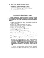
Figure 1 is the flow diagram of a typical fluid catalytic cracking unit at an oil refinery. Preheated liquid gas oil is
fed into the bottom of the catalytic cracker where it comes in contact with the newly regenerated hot alumina,
silica or zeolite catalyst. This contact vaporizes the gas oil and begins the cracking reaction on the hot catalyst
surface. The catalyst is in the powdered form and is carried upward, along with the gas oil vapors, from the riser
section into the reactor vessel where all of the catalytic cracking reactions are completed. The major reaction
products are the shorter chain hydrocarbons, but some carbon monoxide and carbon are also formed. The
carbon, referred to as coke, deactivates the cracking catalyst and must be removed on a frequent basis in order
to maintain an optimum catalytic cracking process.
Figure 1: Schematic of FCC Unit
The hydrocarbon products exiting the fluid catalytic cracking process reactor are separated from the catalyst
particles by flow impingers followed by cyclonic separators. The hydrocarbon products are subsequently sent to
a fractionation column for product separation while the separated catalyst is sent to a regenerator. The catalyst is
first steam stripped to remove any hydrocarbons from it prior to regeneration by coke burnoff.
The coke burn-off is accomplished in the regeneration vessel by addition of air to react with the coke and also to
fluidize the catalyst. This burn-off is exothermic and and occurs at 1,000
°
F to 1,200
°
F in a partial catalyst
regenerator operated at low levels (500 ppmv or less) of oxygen from added air. The burn-off occurs at 1,200
°
F
to 1,400
°
F in cases where a complete combustion regenerator is used and operated at 1-3% oxygen levels by
adding excess air.
SO
x
scavenging additives also may be added to the regenerator in order to reduce SO
x
emissions, and fresh
catalyst may also be added to make up for losses from the system. Gases exiting the catalyst regenerator are
separated by cyclones from the solid catalyst that is to be recycled. The particulate and gaseous emissions from
the catalyst regenerator are the major air emission source from the catalytic cracking process.
Catalytic Reforming
Catalytic reforming employs a series of reactions conducted over a platinum or platinum/rhenium catalyst to
change or reform the structure of hydrocarbons. The purpose of these reactions in an oil refinery is to increase
the octane value of the hydrocarbons by, for example, dehydrogenating naphthenes to form aromatics.
The naphtha used as a reforming process feedstock is first treated to remove sulfur from it since that would
poison the platinum in the reforming catalyst. The reaction is endothermic and heat must be applied to the
process in between the multiple reactors used in series for the reforming process. Two other types of catalytic
reforming use either cyclic regeneration or continuous regeneration of the catalyst. Heat exchangers and fired
heaters are used to add the required heat to the reforming process, and they are a significant source of refinery
air emissions (Table 1). In addition, the reforming catalyst must be regenerated on a regular basis, and this is also
a significant air emission source in a refinery.
In a catalytic reformer, the liquid naphthas are first either desulfurized by reaction with zinc oxide to form zinc
sulfide or hydrodesulfurized over a cobalt-molybdenum catalyst to form hydrogen sulfide. The resulting sulfur
dioxide (from regenerating zinc sulfide) or hydrogen sulfide is then sent to the sulfur recovery plant of the refinery.
The liquid naphtha feedstock is next raised to reaction temperature by passing it through a heat exchanger into
the first stage reforming reactor. Once the reforming reaction is partially completed, the temperature of the liquid
in the first reactor stage has decreased and reforming stops. The liquid naphtha/aromatic mixture then passes
through a second heat exchanger to raise it back to reaction temperature before entering the second stage
reforming reactor. This sequence of heat exchange and then reaction is repeated in subsequent stages until the
desired naphtha conversion to aromatics is achieved.
The reforming catalyst must be regenerated on a regular basis because it is deactivated by carbon buildup (coke)
or catalyst poisons present in the naphtha feedstock. The catalyst must be regenerated by shutting down the
reforming process, by removing individual reactors from the process or by continuously regenerating a small
fraction of the total amount of catalyst in the reactors. Each has advantages and disadvantages, and therefore all
three methods of catalyst regeneration are practiced worldwide.
Semi-regenerative reforming technology interrupts the reforming process when the catalyst must be regenerated.
The reactors are then depressurized and any hydrocarbon vapors purged with nitrogen to a carbon adsorber,
thermal oxidizer or refinery flare. Air is then introduced and recirculated through the compressor to allow coke
burn-off to occur under controlled conditions. Chlorine must be added to the catalyst at this time to return it to
the active form (metal chloride). Hydrogen must then be introduced to reduce the regenerated metal catalyst
from the oxide form. The latter two catalyst regenerating steps produce significant hydrochloric acid emissions.
Sulfur Recovery Plant
Sulfur in the crude oil feedstock is converted to predominately hydrogen sulfide (also called acid gas) during the
cracking and hydrotreating processes at an oil refinery. The acid gas is normally removed from the cracking and
hydrotreating process exhausts by an amine solvent absorption process. The amine solution is regenerated by
heating and the concentrated acid gas is then sent to a sulfur recovery plant located within the refinery. The
exhaust of the sulfur recovery plant, as reported in Table 1, contains reduced sulfur compounds ( COS, CS
2
and
H
2
S ) that are potentially toxic air pollutants. They are also extremely odorous compounds that can result in
10/25/12 Ref inery Process Air Emissions
6/10www.mcilv ainecompany .com/brochures/ref inery _process.htm
community odor complaints.
A typical sulfur recovery plant uses the Claus process, or a variation thereof. Approximately one third of the acid
gas is combusted with air to form sulfur dioxide, which in turn is reacted with the hydrogen sulfide in the acid gas
stream. The reaction is catalyzed by activated alumina and produces solid sulfur, water vapor and heat ( 2H
2
S +
SO
2
= 3S + 2H
2
O ). This is a reversible reaction so it is conducted in a series of reactors with cooling between
reactors in order to condense out the solid sulfur product. This drives the reaction towards completion in order
to maximize hydrogen sulfide removal efficiency. Auxiliary burners then reheat the gas stream prior to the next
reactor in order to maximize the reaction rate.
The recovered sulfur can be used within the refinery to produce sulfuric acid if there is an onsite sulfuric acid
plant. Many oil refineries use sulfuric acid in isomerization and alkylation processes to increase the value of their
petroleum products. If not, the sulfur can be sold for use in producing sulfuric acid offsite or for use in other
processes requiring elemental sulfur. There is currently little or no profit in producing sulfur from a Claus plant,
but this sulfur removal process is usually the most cost-effective method of reducing refinery sulfur compound air
emissions.
In order to meet stricter air pollution regulations, many oil refineries in the United States, Japan and Europe have
installed sulfur removal processes on the tail gas from the Claus process. The commonly employed methods of
tail gas treatment include catalytic reduction, amine absorption and incineration. Catalytic reduction produces
hydrogen sulfide from the mixed sulfur compounds in the Claus plant tail gas that can be absorbed in amine
solvent and recycled back to the inlet of the sulfur recovery plant. Amine absorption increases the hydrogen
sulfide removal efficiency of the Claus plant by reducing the hydrogen sulfide content of the tail gas. Thermal
oxidation or incineration converts all sulfur compounds in the Claus plant tail gas to sulfur dioxide which can be
scrubbed and neutralized to produce sodium sulfite or sodium bisulfite.
The emissions from the sulfur recovery plant occur in the exhaust from the Claus plant, if no tail gas treatment is
used, or the exhaust from the tail gas treatment unit. The exhaust gas from the Claus process usually contains less
than 1% mixed sulfur compounds, indicating a sulfur removal efficiency of over 98%. A tail gas treatment
process can reduce the mixed sulfur compounds in the Claus plant exhaust to less than 100 ppmv, increasing the
overall sulfur removal efficiency from the tail gas to over 99.9%.
Delayed or Fluid Coking
Delayed or fluid coking is a thermal cracking process that upgrades the value of refinery vacuum distillation
residues and aromatic oils. The vacuum distillation residues contain asphaltic compounds which are primarily
heterocyclic hydrocarbons. The aromatic oils, usually decant oil or pyrolysis residues, are primarily polynuclear
aromatics with six carbon aromatic rings fused together. The decant oil is a residue of the catalytic cracking
process whereas the pyrolysis residues are from the thermal cracking process.
Coking operations can be used to upgrade any low volatility residual solids in the refinery to improve their
economic value. It is literally a petroleum refinery “garbage can” to dispose of undesirable residuals by turning
them into valuable products.
Coking also removes metals and other contaminants from the coker feed and concentrates them in the solid
coke. The liquid and gaseous products of delayed or fluid coking are therefore more suitable for internal refinery
use than for sale. Coking sharply reduces the volume and disposal cost of solid wastes from an oil refinery by
converting them into useful byproducts. The value of fluid or delayed coking to a modern refinery is almost
10/25/12 Ref inery Process Air Emissions
7/10www.mcilv ainecompany .com/brochures/ref inery _process.htm
incalculable in these times of strict environmental regulations.
Delayed coking is the predominant coking method in petroleum refineries but some have adopted a newer
coking method called fluid coking. Approximately 75 percent of refineries with coking operations use delayed
coking whereas approximately 25 percent use a fluid coking process. Delayed coking has no significant air
emissions but fluid coking produces air emissions consisting of coke fines.
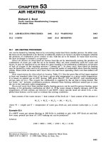
Figure 2 is a flow diagram of a refinery delayed coking unit. Fluid coking is a continuous process where a fluid
bed reactor is heated to convert the non-volatile coker feed (e.g. vacuum distillation residue) into solid coke and
a mixture of non-condensable gaseous volatile liquid products that can be fractionated in subsequent process
steps. The cold coke exits the fluid bed reactor at the bottom while the volatile liquid and gaseous products exit
the reactor at the top. The latter are separated in the coke fractionator, which is a distillation column dedicated to
the delayed coking process. The coke fractionator is normally operated with liquid sprays onto some of the
distillation trays in order to prevent coke formation that plugs the trays. The coke is hydraulically transported
into the process heater where it is reheated and either returned to the fluid bed reactor or sent to a coke
recovery and storage area. This latter step is where coke fines can become airborne air pollutants.
Figure 2: Schematic of Delayed Coking Unit
Because the feedstock of a delayed or fluid coker has a high sulfur content, gaseous sulfur compounds are
produced. Gaseous hydrocarbons and organic HAPs (e.g. benzene) are also produced in the delayed coking
process. They are recovered in the coker fractionator whereas the gaseous sulfur compounds are usually sent on
to the sulfur recovery plant and removed there. Carbon monoxide is also produced which is usually incinerated
for its fuel value in a CO boiler. The only direct releases to atmosphere from the coking process is therefore
particulates
Storage Vessels
Storage tanks and spheres are typical vessels used at oil refineries to contain crude oil, processed intermediates
or refined products. Cylindrical tanks are generally used for storage of volatile liquids (e.g. gasoline) whereas
spheres are generally used for storage of condensable (e.g. propane under pressure) or non-condensable gases
(e.g. methane). Tanks may have either a floating roof with a sliding seal attachment to the tank sides, where the
roof rises and falls with the liquid level, or a fixed roof that is permanently attached to the tank sides and does not
move. As the temperature changes due to ambient condition changes, the floating roof tank adjusts the liquid
volume automatically and vapor losses are minimal. Adding a second sliding seal will virtually eliminate vapor
volume automatically and vapor losses are minimal. Adding a second sliding seal will virtually eliminate vapor
losses. A fixed roof tank has no such flexibility and a vapor head space exists above the liquid level of the tank.
When the liquid level falls along with the liquid temperature, hydrocarbon vapors are created in the head space
above the liquid hydrocarbons. Then, when the liquid level rises along with the liquid temperature, hydrocarbon
vapors escape the tank as fugitive air emissions that may need to be controlled.
Wastewater Streams
Wastewater streams in an oil refinery usually contain traces of hydrocarbons as well as dissolved amine or sulfur
compounds. During the transfer of the wastewater from the process to the central treatment facility,
hydrocarbon, amine and sulfur compound vapors can escape into the atmosphere as fugitive emissions. The usual
fugitive emission sources are open trenches, collection sumps and wastewater collection system vents. Open top
wastewater treatment units such as oil/water (API) separators, aeration basins, clarifiers, etc. can also be the
source of fugitive air emissions.
Cooling Towers
Cooling towers evaporate water in order to remove the excess heat from processing units at an oil refinery.
Cooling water is cycled continuously between the cooling tower and the processing units where the heat is
generated in order to accomplish this. Although in theory the cooling water is never in direct contact with the
liquid hydrocarbons being processed, in reality leaks and cross contamination sometimes does occur. Therefore
volatile hydrocarbons may be evaporated in the cooling tower as well as some of the cooling water. This results
in fugitive hydrocarbon air emissions.
Equipment Leaks
Equipment leaks normally encountered in an oil refinery include pipe flanges, threaded pipe connections, pump
seals, compressor seals and valve packing. There are literally thousands of such potential leak sources in a
typical oil refinery. Reasons for leaks can include normal wear and tear, poor quality or design of components,
poor maintenance or improper choice of materials. Volatile hydrocarbons can then be leaked from the
processing units into the ambient environment from any of the above mentioned sources. Leak detection and
repair programs can reduce but not eliminate these fugitive emissions.
Blowdown System
Blowdown systems permit the removal of liquids and vapors from process units in order to permit shutdown of
the process unit for maintenance/repair or to prevent dangerous high temperature or high pressure conditions
from occuring in it. A refinery blowdown system consists of valves, piping, surge vessels, etc. to allow safe
transfer of process liquids or vapors out of each process unit. Because this transfer can allow the release of very
concentrated air emissions, the blowdown system is usually connected to a refinery flare unit in order to destroy
these high concentration air emissions.
Vacuum Distillation
Vacuum distillation, which follows the atmospheric distillation of crude oil, allows the separation of very high
boiling point petroleum fractions without decomposing and polymerizing them. Topped crude from the
atmospheric distillation unit is first heated to about 400
°
C by a process heater, then it is flashed into a vacuum
distillation column maintained at absolute pressures below 1500 kilograms per square meter. This allows
separation of the topped crude into common boiling point fractions by vaporization and condensation. Air
emissions are from condensers following the steam ejectors and vacuum pumps used to maintain the vacuum in
10/25/12
9/10www.mcilv ainecompany .com/brochures/ref inery _process.htm
emissions are from condensers following the steam ejectors and vacuum pumps used to maintain the vacuum in
the distillation column. The hydrocarbon emissions are usually controlled by incineration in process furnaces or
steam boilers.
Steam Boilers
Steam boilers are used in oil refineries to provide indirect heat for process units and also vacuum for steam
ejectors used, for example, in vacuum distillation units. Fuel is combusted in an insulated chamber and transferred
to water in tubes in order to generate the steam. The flue gas from the combustion chamber then exits the boiler
through an exhaust stack. Air emissions occur both from the combustion of fuel impurities (e.g. particulates and
sulfur) and from the combustion process itself (e.g. NO
x
and CO). Steam boilers use natural gas, refinery fuel
gas, fuel oil or residual oil as fuel. The potential air emissions are the least with natural gas fuel and are the most
with residual oil as a fuel. In some refinery boilers cogeneration of both steam and electric power is practiced.
Process Furnaces
Process furnaces are used in oil refineries in order to heat viscous process fluids or solids to a very high
processing or transfer temperature. Fuel is combusted in an insulated chamber and the heat transferred to either
tubes or a cylindrical vessel containing the viscous fluid or solid. In some case the hot flue gas of the furnace is
directly in contact with the viscous fluid or solid. A good example is the above mentioned fluid coking process.
Air emissions occur from the combustion of fuel impurities (e.g. metals and sulfur resulting in particulates and
SO
x
) or from the combustion process itself (e.g. NO
x
and CO). Process furnaces use natural gas, refinery fuel
gas, fuel oil or residual oil as fuel. The potential air emissions are greatest with residual oil as a fuel.
Process Heaters
Process heaters are used in oil refineries to indirectly heat process fluids to a moderate processing temperature.
A good example is the above mentioned catalytic reforming process. Fuel is combusted in an insulated chamber
and the heat transferred to either tubes or a cylindrical vessel containing the process fluid. Air emissions occur
from the combustion of fuel impurities (e.g. particulates and sulfur) or from the combustion process itself (e.g.
NO
x
and CO). Process heaters use natural gas, refinery fuel gas, fuel oil or residual oil as fuel. The potential air
emissions are the least with natural gas fuel and are the most with residual oil as a fuel.
Compressor Engines
Compressors are used to generate the high internal pressure required in certain refinery processes (e.g.
hydrotreating units) in order to optimize process yield. These compressors are driven by either reciprocating
internal combustion engines or by gas turbines. Fuel combustion in engines results in an exhaust gas containing air
emissions. Air emissions occur from either the combustion of fuel impurities (e.g. particulates and sulfur) or from
the combustion process itself (e.g. NO
x
and CO). Reciprocating compressor engines use natural gas, refinery
fuel gas or diesel oil as a fuel. Their potential air emissions are the least with natural gas fuel and are the most with
diesel oil as a fuel. More recently, gas turbines have been employed to drive very large oil refinery compressors.
They use natural gas, refinery fuel gas or distillate oil as a fuel. Their potential air emissions are the least with
natural gas fuel and are the most distillate oil as a fuel.
Barge or Ship Loading
Barge or ship loading requires the transfer of crude oil or refined products such as gasoline from on shore
storage tanks to the barge or ship tank. The barge or ship tanks, while filling, allow vapors of the crude oil or
10/25/12 Ref inery Process Air Emissions
10/10www.mcilv ainecompany .com/brochures/ref inery _process.htm
storage tanks to the barge or ship tank. The barge or ship tanks, while filling, allow vapors of the crude oil or
refined products to build up in the tank which must be vented to atmosphere along with the air displaced from the
tank. The hydrocarbon emissions contained in the vented air are usually conducted to an emission control device
(refrigerated condenser, absorber, adsorber or incinerator) and either destroyed or recovered for reuse
Gasoline Rack Loading
Gasoline rack loading requires the transfer of refined products such as gasoline from refinery storage tanks to a
tank truck. Filling the tank truck allows vapors of the refined product to build up in the tank which must be
vented to atmosphere along with the air displaced from the tank. The hydrocarbon emissions contained in the
vented air are usually conducted to an emission control device (refrigerated condenser, adsorber or incinerator)
and either destroyed or recovered for reuse.