The bioliq® bioslurry gasification process for the production of biosynfuels, organic chemicals, and energy pdf
Bạn đang xem bản rút gọn của tài liệu. Xem và tải ngay bản đầy đủ của tài liệu tại đây (4.56 MB, 44 trang )
ORIGINAL Open Access
The bioliq
®
bioslurry gasification process for the
production of biosynfuels, organic chemicals, and
energy
Nicolaus Dahmen
*
, Edmund Henrich
*
, Eckhard Dinjus and Friedhelm Weirich
Abstract
Background: Biofuels may play a significant role in regard to carbon emission reduction in the transportation
sector. Therefore, a thermochemical process for biomass conversion into synthetic chemicals and fuels is being
developed at the Karlsruhe Institute of Technology (KIT) by producing process energy to achieve a desirable high
carbon dioxide reduction potential.
Methods: In the bioliq process, lignocellulosic biomass is first liquefied by fast pyrolysis in distributed regional
plants to produce an energy-dense intermediate suitable for economic transport over long distances. Slurries of
pyrolysis condensates and char, also referred to as biosyncrude, are transported to a large central gasification and
synthesis plant. The bioslurry is preheated and pumped into a pressurized entrained flow gasifier, atomized with
technical oxygen, and converted at > 1,200°C to an almost tar-free, low-methane syngas.
Results: Syngas - a mixture of CO and H
2
- is a well-known versatile intermediate for the selectively catalyzed
production of various base chemicals or synthetic fuels. At KIT, a pilot plant has been constructed together with
industrial partners to demonstrate the process chain in representative scale. The process data obtained will allow
for process scale-up and reliable cost estimates. In addition, practical experience is gained.
Conclusions: The paper describes the background, principal technical concepts, and actual development status of
the bioliq process. It is considered to have the potential for worldwide application in large scale since any kind of
dry biomass can be used as feedstock. Thus, a significant contribution to a sustainable future energy supply could
be achieved.
Keywords: bioliq, biomass, bioslurry, biosynfuel, bi osyngas, entrained flow gasification, fast pyrolysis, dimethyl
ether, gasoline
Background
Only 200 years ago, t he energy supply of a one billion
world population depended entirely on renewables . The
main energy source was firewood for residential heating,
cooking, and lighting, as well as serving for high-tem-
perature processes like iron ore reductio n, burning
bricks and tiles, or glass melting, etc. A complementary
energy contribution was mechan ical energy from hy dro-
power for hammer mills or wind energy for windmills
and sailing ships. Not to forget that the main power
source for human activities carried out by working ani-
mals and human workers has been fuelled by biomass.
Large energy plantations in the form of grassland and
arable land (e.g., for g rass, hay, o at, etc.) were devoted
to ‘transportation fuel’ production for horses, donkeys,
camels, etc.
A well-es tablished organic chemical industry based on
various biomasses also existed until about a century ago.
Examples are the coproducts from thermochemical
charcoal production like tar and pitch, e. g., as a glue for
ship construction, wood preservatives, turpentine, ‘wood
spirit’ (methanol), or ‘wood vinegar’ (acetic acid), etc. or
biochemical wine and beer production by sugar and
starch fermentation. It took many decades of
* Correspondence: ;
Institute of Catalysis Research and Technology, Karlsruhe Institute of
Technology (KIT), Campus Nord, Eggenstein-Leopoldshafen, D-76344,
Germany
Dahmen et al. Energy, Sustainability and Society 2012, 2:3
/>© 2012 Dahmen et al; licensee Springer. This is an Open Access article distributed under the terms of the Creat ive Commons
Attribution License ( which permits unres tricted use, distribution, and reproduction in
any medium, provided the original work is properly cited.
development efforts until the major organic chemicals
could be manufactured by cheaper synthetic processes
from coal, crude oil, or natural gas.
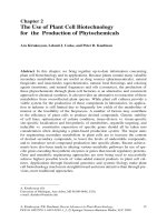
Mid-2011, a world population of 7 billion people co n-
sumes around 13 Gtoe/a of primary energy [1]. The
world primary energy mix consists of ca. 80% fossil fuels
and ca. 10% bioenergy as shown in Figure 1. Towards
the end of the century, an increa se of the world popula-
tion to a maximum of almost 10 billion is expected in
combination with a doubling of the energy consumption
to about 25 Gtoe/a. This corresponds to an average
energy consumption of 3.4 kW(th)/capita or about two-
thirds of the present per capita consumption in the Eur-
opean Union (EU 27). The economic growth takes place
in the highly populated and rapidly growing and devel-
oping nations mainly in China, India, Indonesia, the
neighboring South East Asia region, and in South Amer-
ica, e.g., Brazil, and comprises more than half of the
future world population.
If the high fossil fuel share of ca. 80% would be main-
tained in the future energy mix, the proven and eco-
nomically recoverable overall coal, oil, and gas reserve s
of almost 2 Ttoe [1] known in 2010 will be depleted in
about a century as a cont inuation of the present con-
sumption rate: first the oil in 43 years, then the gas in
62 years, and the larger coal reserves at the end in
almost 400 years. However, coal will be consumed much
faster when it has to take over the large oil and gas
share. Together with a doubling of the energy consump-
tion, the realistic, dynamic lifetime shrinks to a little
more than 100 years. In this scenario, the present CO
2
content of 386 v/v in the atmosphere will about to dou-
ble and cause global warming of several kelvin with ris-
ing sea levels and more frequent weather excursions.
To gradually replace the dwindling fossil fuels in the
course of this century, renewable direct (photovoltaics
and solar thermal) and indirect (hydropower, wind
energy, and bioene rgy) solar energies and quasi-inex-
haustible energy sources like nuclear breeder and fusion
reactors as well as some smaller contributions from
geothermal and tidal energies must therefore urgently
be developed to c ommercial maturity. The i nevitable
switchov er of our energy supply from the finite fossil to
renewable and - from a human point of view - quasi-
inexhaustible energy sources requires much financial
effort, time, and innovative ideas and will heavily strain
human and material resources. Development and market
introduction must be achieved in due time to avoid
armed conflicts in ca se of a shortening or breakdown of
energy supply. This task belongs to the major challenges
of our century. Biomass must and can co ntribute an
indispens ible and significant part to a sustaina ble future
energy supply, but with present-day technologies, it can
by no mean s serve all energy needs of mankind. High
priority has to be given to technology research and
development for the inevitable exploitation of biomass
Figure 1 World primary energy mix 2010.
Dahmen et al. Energy, Sustainability and Society 2012, 2:3
/>Page 2 of 44
as the o nly renewable carbon source for organic chemi -
cals and fuels. Bioenergy is an inevitable by-product of
the increasingly important biocarbon utilization.
Biomass potential
Biomass growth
Only about half of the 175 trillion kW(th) of solar radia-
tion incident on the outer atmosphere of the earth
arrives directly at the earth’s surface, and only 0.11% of
this surface energy is converted by photosynthesis to
about 170 Gt/a of dry biomass (higher heating value
(HHV), 5 kWh/kg), equivalent to 70 Gtoe/a of bioenergy
(HHV oil, 12 kWh/kg). About 65% or 45 Gtoe are gen-
erated on land, and 35% or 25 Gtoe, in the oceans. At
present, there are only speculations on how a significant
fraction of the ocean biomass can be exploited, e.g., by
biochemical processes in salty seawater.
About 29% of the 510-million-km
2
earth surface is
land. Of the 148-million-km
2
land surface area, almost
40% is unfertile desert (too dry), tundra (too cold), or
covered with ice. The large deserts of the earth extend
around the tropic at latitudes of 23° north and south
and separate the fertile tropical zone fr om the subtropi-
cal and temperate zones. About half of the about 90-
million-km
2
fertile global land areas are forests; the rest
of ca. 45 million km
2
are farmland (ca. 15-million-km
2
arable land plus grassland), savanna, and settlement area
[2,3].
The average global upgrowth on fertile land is ca.1.2
kg of dry biomass or 6 kWh(th)/m
2
/year, with a large
regional scatter of at least half an order of magnitude.
Harvest expectations for plantations are 2 kg of dry bi o-
mass (containing ca. 1 kg of carbon) per m
2
and year.
Biomass combustion for electricity generation with an
optimistic 45% efficiency would yield about 0.3 to 0.5
Watt(el)/m
2
. Commercial photovoltaic cells are almost
two orders of magnitude more efficient. Yet today,
photovoltaics are still more expensive than biomass cul-
tivation and harvest plus final combustion in conven-
tional biomass-fired power stations.
Essential for optimal plant growth are suitable soils,
temperatures, sufficient water, and fertilizer supply dur-
ing the right time. C3-plants are typical for temperate
climates and need about 400 kg of water transpiration
via their leaves to generate 1 kg of dry biomass. C4-
plants, typical for tropical and subtropical climates, need
only about half. With the average rainfall on earth of
roughly 700 mm/a and suitable temperatures and soil
fertility, a maximum biomass harvest of about 2.5 kg/m
2
(25 t/ha) can be expected for C3-plants in temperate cli-
mates; with C4-plants in tropical regions without winter
season, up to 50 t/ha may be possible. Such optimum
harvests may be obtained in energy plantations with irri-
gation and two harvests or more per year. The present
world avera ge harvests are only about half of the poss i-
ble maximum. There is doubt if an optimum P-fertiliza-
tion can still be provided in the future without ash
recycle. In particular for large-scale biomass conversion
plants, recovery of phosphorous and other minerals is a
must.
In the EU 27 with 1,160,000-km
2
arable land, a part of
6.7% is already set aside [4] to avoid an expensive over-
production of food. If optimum agricultural technologies
are applied in all EU countries, up to 20% of the arable
land or even more can be set aside or used for biomass
plantations. Assuming an average harvest of 20 t/a of
dry biomass/ha, a total harvest of almost 0.2 Gtoe/a
(containing 0.25 Gt o f biocarbon) might be realized in
few decades. Even without the residues from agricu lture
and forestry in comparable amo unts, this is sufficient
forasustainablesupplyofbothorganicchemistryand
aviation fuel production. Most studies estimate that the
bioenergy contri bution in the EU will increase to more
than 10% after 2020 and to more than 20% on the
longer term [5]. In the latter c ase, the major part must
then be supplied from energy plantations. Different
from agricultural or forest residues, all direct and indir-
ect costs of plant cultivation must then be charged to
the bioenergy. The advantages of energy plantations in
tropical regions are clearly visible in T able 1 from the
two to three times higher hectare yields for liquid
biofuels.
Competitive biomass use and harvest limits
The most abundant constituent of terrestrial plants is
lignocellulo se with more than 90 wt.%, the water-insolu-
ble polymeric construction material of the cell walls.
Dry lignocellulose is composed of about 50 wt.% cellu-
lose fibers, wrapped up and protected in sheets of ca.25
wt.% hemicellulose and ca. 25 wt.% lignin. Any l arge-
scale biomass use must rely on this m ost abundant bio-
carbon material. Starch, sugar, oil, or protein in food
crops are far less abundant, and their use as human or
animal food or feed has the highest priority.
It is an important issue how much of the terrestrial
biomass upgrowth of ca.45Gtoe/a(ca.110Gt/aofdry
biomass) is possible and desirable to harvest. Almost
half of the global land b iomass upgrowth consists of the
annually falling leaves and needles in the forests [ 2],
above all in the tropical rain forests. They can neither
be collected w ith reasonable effort nor used since their
high mineral content makes them indispensible as an
on-site fertilizer. The biomass harvest is further dimin-
ished by harvest losses and residues like tree stocks,
roots, plus stubble of cereals, etc. left on-site, as well as
by storage losses of wet biomass via biological degrada-
tion at more than ca. 15 wt.% water content.
Limits for a secure prevention of overexploitation are
not reliably known. For the EU 27 with an actual gross
Dahmen et al. Energy, Sustainability and Society 2012, 2:3
/>Page 3 of 44
inland energy consumption of 1.9 Gtoe/a, the bioene rgy
contribution of 4% is estimated to increase sustainably
to almost 15% or 300 Mtoe/a of the energy consump-
tion expected for 2030 [4,5]. A rather optimistic p oten-
tial future scenario is presented in Table 2: about a
quarter of all terrestrial biomass upgrowth or 11 Mtoe/a
can be harvested and used sustainably for all biocarbon
and bioenergy applications. This is almost three times
thepresentuseandprobablynotfarfromasustainable
upper limit.
Human and animal food production is indispensible
and is the first priority. The secon d priority is stem
wood utilization as the still dominant organic construc-
tion material (timber) as well as the production of
organic raw materials like cellulos e fibers from wood or
cotton, caoutchouc, or extracts l ike flavors, drugs, dyes,
etc. In the future, when the fossil hydrocarbon reserves
become too expensive or exhausted, all applications uti-
lizing biofeedstock as the only renewable carbon
resource will gradually gain higher priorities. Direct bio-
mass combustion for heat, power, and electricity genera-
tion today still enjoys high priority to fight global
warming because combustion is in most cases econom-
ically more favorable than using lignocellulosic biocar-
bonviagasificationorfermentationastheonly
renewable carbon raw material f or organic c hemicals
and fuels [6], yet this is only an intermediate situation
as long as fossil fuels are still available. All other renew-
able energy sources produce heat or electricity directly
but no carbon. Moreover, thermochemical biomass con-
versions also generate energy as an inevitable couple-
product in the form of reaction heat and sensible heat
of the reaction products. In future biorefineries, the
cogeneration of energy will be normal and used to rise
high-pressure steam, power, or electricity, mainly to
supply the own self-sustained process and to export any
potential surplus.
The amount of carbon needed for organic chemistry is
only about 4% compared to the amount which would be
required for global energy supply via combustion. The
2050+ scenario in Table 2 shows that even with a mas-
sive increase of biomass use, only ca. 6 Gtoe/a or about
aquarterofthefutureglobalprimaryenergydemand
can be covered by biomass. Supply of the much smaller
Table 1 Potential biofuel yields per hectare in temperate and tropical climates
Climate Crop/country Crop residue Biofuel type Yield
(t/ha)
Diesel equivalent
(sum; t/ha)
Temperate climate Sugar beet; Germany Sugar Ethanol 4 3
Rape seed; Germany, USA Oilseed;
straw
FAME;
FT diesel
1.2;
0.5
1.7
Tropical climate Palm oil; Malaysia Oilfruits;
palm waste
FAME;
FT diesel
6;
2
8
Sugar cane; Brazil Sugar;
bagasse
Ethanol;
FT diesel
6;
2
6.5
FT, Fischer-Tropsch.
Table 2 Biomass utilization scenario compared to the present use
Biocarbon/bioenergy use Year/population
2011/7 billion
(Gtoe/a
a
)
2050+/10 billion
(Gtoe/a
a
)
Biocarbon use for
1. Human plus domestic animal food and feed;
food harvest residues (e.g., straw)
ca.2
< 0.2
2.5
0.5
2. Construction wood (timber) 0.5 > 1
3. Plantations for special organic raw materials (cellulose fiber, cotton, pulp and paper, caoutchouk,
oilseed for detergents, etc.)
ca. 0.2 1
4. Synthetic organic chemistry by bio- and thermochemical routes with cogeneration of energy < 0.1 1
Bioenergy use for
5. Traditional firewood combustion, etc. 1 1
6. Energy for high-temperature processes (cement, lime, bricks, ceramic production, etc.) < 0.1 0.5
7. Ore reductant (mainly iron ore) < 0.1 0.5
8. Aviation, ship, and special car fuels (assuming 50% BTL energy conversion efficiency) < 0.1 2
9. CHP in remote areas < 0.1 1
Total biomass consumption (1 to 9) ca.4 ca.11
a
1 Gtoe is ca. 2.4 t of lignocellulose free of water and ash. BTL, biomass to liquid; CHP, combined heat and power.
Dahmen et al. Energy, Sustainability and Society 2012, 2:3
/>Page 4 of 44
carbon fraction for organic chemistry does not cause
much problem.
In some cases, carbon-b ased energy production is dif-
ficult to replace, in particular in the transportation sec-
tor. Even if all road transport can be electrified, a
significant amount of l iquid hydrocarbon transportat ion
fuel will be needed at least for aviation, probably also
for ship transport and for car, bus, and truck transports
in remote areas. Producing 1 Gtoe/a of biosynfuel for
these special applications requires ca. 2 Gtoe/a of l igno-
cellulose as a ra w material, a significant share of the
total bioenergy harvest. Carbon materials are also
needed for iron ore reduction, ca. 0.5 Gtoe/a of charcoal
mightbeareasonableestimatetowardtheendofthe
century. In steel and glass production, as a part of the
high-temperature process, heat can be supplied in the
form of electr icity. Corresponding electro-technologies
do not exist for the present global cement production of
2.2 Gt/a or for b ricks, lime, ceramics, tiles, etc. produc-
tion. The traditional direct biomass combustion for
home heating and co oking is assumed to continue at
the present level together with some additional CHP
applications.
Wood and straw
The terms wood and straw are used here only as syno-
nyms for slow- and fast-growing lignocellulosic biomass
with low (< 3 wt.%) or higher ash content, respectively.
Wood without bark is a relatively clean biofuel with a
typical ash content of 1 wt.% or below. Fast-growing
biomass from agriculture like cereal straw, grass, hay,
etc. has an ash content between 5 and 10 wt.%, rice
straw even 15 to 20 wt.%. Wood ash contains much
CaO, straw ash about half SiO
2
with much K and Cl.
These and other inorgan ic constituents are needed as
part of the biocatalyst systems, which are responsible for
a faster metabolism. Higher ash and heteroatom (e.g., N,
S) contents are therefore also typical for the faster grow-
ing aquatic plants and for active animals. This is simul-
taneously a hint to higher fertilizer costs for plant
cultivation.
Combustion and gasification technologies for low-
quality biofuels with m uch ash are not well developed.
Special technical problems with straw and straw-like
materials in thermochemical processes are:
• Potassium can reduce the ash melting point down
to less than 700°C (eutectics!). Sticky ash during
either combustion or gasification increases the risk
of reactor slagging.
• Chlorine is released mainly as HCl, causing corro-
sion in gas cleaning facilities, poisoning catalysts,
and potentially inducing the formation of toxic poly-
chlorinated dibenzodioxins or furans due to unsuita-
ble combustion conditions.
• Volatility of alkali chlorides (in particular of KCl)
at temperatures above 600°C can cause deposits,
plugging, and corrosion in gas cleaning systems.
• Ash and volatile organic carbon impurities can cre-
ate problems during co-combustion or co-gasifica-
tion. Fuel nitr ogen in the form of proteins is partly
converted to NO.
• High nitrogen contents are mainly converted to N
2
and must be compensated by expensive N-fertilizers.
Thermochemical processing is therefore not suited
for protein-rich biomass (N = 16% of the protein
weight) with a N content above about 3 wt.%.
The elementary CHO composition of dry, ash-, and
heteroatom-free lignocellulose in different biofeedstock
is almost the same and well represented by C
1
H
1.45
O
0.66
.
A reasonable sum formula with integer atom numbers is
C
6
H(H
2
O)
4
≙C
1
H
1.5
O
0.67
or C
9
H(H
2
O)
6
≙C
1
H
1.44
O
0.67
.
An even simpler and still reasonable sum formula is C
3
(H
2
O)
2
≙C
1
H
1.33
O
0.67
, a 1:1 formal mix of carbon and
water in weight. The HHV of dry, ash-free lignocellulose
is ca. 20% higher than a simple 1:1 wt.% carbon/water
mix. However, this simple picture is useful for quick
stoichiometric estimates. In comparison to glucose, as
the primary organic product of photosynthesis, the sum
formula C
6
H
8
O
4
is also used. To represent real biomass,
some ash and moisture must be added to the lignocellu-
lose. Heteroatoms like N or S can, in most cases, be
neglected to a first approximation, except in protein-
rich biomass (nitrogen in protein, ca. 16 wt.%). The sul-
fur content usually is rather low, about an order of mag-
nitude compared to coal.
Basic concept considerations
Biomass utilization will increase in the future not only
due to the growing food consumption for a larger popu-
lation, but also due to the extension of old and new
bioenergies and especially biocarbon a pplications,
required to gradually substitute fossil carbon and hydro-
gen. Our tec hnology selection criteria for biomass refin-
ing processes have been based on g eneral and g lobal
considerations [7], not on regional particularities.
Conclusions from the above-mentioned aspects
• Bioenergy generation at the expense of poor food
supply must be strictly prevented. Direct use of bio-
materials with complex chemical and physical struc-
tures like wood as construction material, cotton,
caoutchouc, etc. has also a higher priority than
combustion.
• Use of biomass as the only renewable carbon
resource for valuable organic materials, c hemicals,
and fuels has a higher priority than the generation of
bioenergy via combustion.
• At present, the most urgent task is the develop-
ment of biomass conversion technologies for liquid
Dahmen et al. Energy, Sustainability and Society 2012, 2:3
/>Page 5 of 44
transportation fuels [8] to decrease our oil depen-
dency. Supply security is the most important aspect
on the short term. Politically motivated brief
shortages of oil supply or extremely high prices of
crude oil can cause a serious breakdown of the
world economy with a risk of armed conflicts.
• Biorefineries are an inevitable long-term develop-
ment task for the production of all types of carbon
materials from biomass. Biomass conversion to
organic chemicals or to liquid transportation fuels
requires several chemical reactions in succession.
Energy is an inevitable couple and side product. In
comparison to zer o feed cost, biomass-to-liquid
(BTL) processes require more technical effort than
in an oil refinery. This results in a lower overall
energy recovery in the final product and higher man-
ufacturing costs.
• Biocarbon supply is limited. A secure and sustain-
able upper supply limit for biomass is not reliably
known. An optimistic upper limit estimate after
2050 assumes that about a quarter of a ll land bio-
mass can be exploited for everything from food to
combustion (see Table 2). The present global bioe-
nergy contribution of > 1 Gtoe/a can prob ably be
increased sustainably to ca. 5 to 6 Gtoe/a, a factor of
ca. 5. When bioenergy consumption approaches this
upper limit, not only the biomass prices will
increase, but also the food prices due to the
mutually competitive land use. Because of the
unknown bio-production limits, there is a high risk
of overexploitation with a potential breakdown of
bio-production for decades or centuries, as already
experienced with deforestation in some Mediterra-
nean regions.
• Without fossil carbon, some new or renewed bioe-
nergy applications will emerge, in cases where car-
bon is needed and a direct use of renewable
electrical or mechanical power is unsuited or too
expensive. Examples are:
○ For iron ore reduction, generation of either
charcoal or CO or (CO + H
2
) mixtures via pyro-
lysis is a renewed old technology.
○ Heat generation for high-temperatu re pro-
cesses for cement, bricks, lime, etc. production.
○ Conventional biomass combustion for residen-
tial heating and cooking is assumed to continue
at about the present level and is probably com-
plemented by additional CHP-plants for simulta-
neous heat and electricity generation in remote
areas.
○ In a few decades, road or car electrific ation
will probably complement the electrified rail.
However, the convenient liquid hydrocarbons are
hard to replace as aviation fuels - eventually also
as ship fuels and for the still remaining fraction
of car, truck, and bus fuels. In the course of the
century, the biomass demand for these conven-
tional and new synthetic transportation fuels, tai-
lored for new or optimized engine types, might
probably become higher than that for organic
chemicals. The production technology for bio-
synfuels and organic chemicals do not differ
principally. Ho wever, liquid organic fuels belong
to the cheapest organic chemicals.
• Bioenergy can sustainably cover probably up to a
quarter of the future global primary energy demand.
The crude estimate in Table 2 indicates a maximum
bioenergy contributio n of ca.6Gtoe/aincludingthe
couple-product energy from chemical conversions.
During thermochemical biocarbon conversion, about
half of the initial bioenergy o n the average is typi-
cally liberated in exothermal reactions in the forms
of reaction energy and sensible heat. Recovery and
conversion of half of this energy, e.g., in high-pres-
sure stea m or electricity, m ake use of about a quar-
ter of the initial bioenergy as a couple-product.
Biorefineries
A biorefinery [9] is a flexible coherent system of physical
and chemical facilities for the conversion of all types of
biomass into more valuable organic materials, chemicals,
and fuels; heat, power, and electricity are inevitable cou-
ple and side products from exothermal chemical reac-
tions. This network for the simultaneous cogeneration
of carbon materials and energy is nothing new, but the
normal situation in any integrated multistep organic
chemistry is complex. Biorefineries are the organic che-
mical industry of the future and use biomass as a carbon
raw material. Energy, especially in the f orm of heat or
high-pressure steam, can be consumed on-site to gener-
ate a sel f-sustained process; an energy surplus is usually
exported as electricity a nd credited to the main pro-
ducts. Biorefineries can be classified according to the
main conversion process into:
1. Physicochemical - e.g., pulp and paper mills, sugar
mills, corn mills, fatty acid methyl ester plants, etc.
2. Biochemical - low-temperature wet processes with
high selectivity (ethanol, butanol, biogas, etc.)
3. Thermochemical - high-temperature dry processes
proceed usually via syngas, e.g., BTL technology.
Additional classification aspects - without considering
educts and products - are the main intermediate(s) (plat-
form chemicals), which are suited for mutual e xchange
between plants. This script reports about a development
work for the ‘backbone’ conversion steps of a thermoche-
mical biorefinery: conversion of the abundant
Dahmen et al. Energy, Sustainability and Society 2012, 2:3
/>Page 6 of 44
lignocellulose via biosyngas - a mix of CO and H
2
-asa
versatile intermediate to H
2
,CH
4
,CH
3
OH [10,11],
dimethyl ether (DME), Fischer-Tropsch (FT) hydrocar-
bons, [12] or other carbon products, using highly selective
catalysts at specified temperatures and higher pressures.
Most synthesis steps are known since almost a century
and are practiced already on the technical scale [13,14]
based on coal and natural gas as feedstock known as coal-
to-liquid (CTL) and gas-to-liquid (GTL) processes. Exam-
ples are the CTL plants operated by Sasol in South Africa
or the Shell GTL plants in Malaysia or Qatar. The devel-
opment of BTL is not completed but, to a large extent,
canrelyontheoldcoalconversiontechnologiesinan
improved or modified form. Major development work is
needed especially for the front-end steps to prepare a
clean syngas from various biofeedstock types. After gen-
eration of a clean syngas with the desired H
2
/CO ratio, the
BTL technology is comparable with the practiced CTL
and GTL technologies since it does not make a difference
if the syngas has been produced from coal, oil, natural gas,
biomass, or organic waste. Syngas or C
1
chemistry in gen-
eral is based on a well-known technology [13,15]. This is
why the actual work at the Karlsruhe Institute of Technol-
ogy (KIT) has been focused mainly on the front-end BTL
steps.
Selection of gasifiers for biomass
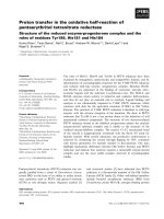
Gasifier types
The typical gasifier types [16] for coal shown in Figure 2
can also be used for lignocellulosic biomass after special
prep aration [17]. Suitable feed particle size and gasifica-
tion reaction times decrease from about 0.1 m and more
than 10
3
s for fixed bed gasifiers, via ca. 1 cm and 10
2
to
10
3
s for fluidized bed gasifiers, down to ≤ 0.1-mm fuel
powders, which react in one or few seconds in an
entrained flow (EF) gasifier flame. Short reactor resi-
dence times and higher pressures result in smaller and
more economic reactors with a higher throughput.
Fixed and fluidized bed gasifiers operate with solid ash
at temperatures below 1,000°C. Low-melting straw ash
can become sticky already at 700°C and can create pro-
blems by bed agglomeration. Raw sy ngas from fixed and
fluidized beds contai ns tar and methane because of the
low gasification temperatures; especially, the syngas
from updraft gasifiers is contaminated with much dirty
pyrolysis gas. Syngas applications for combustion can
tolerate high methane contents and require less gas
cleaning efforts. EF gasifiers operate above the ash melt-
ing point at > 1,000°C and generate a practically tar-
free, low-methane raw syngas.
Because of the higher temperatures in an EF gasifier, a
cleaner syngas is obtained at the expense of more oxy-
gen or air consumption and correspondingly lower cold
gas efficiency. However, this i s at least partly compen-
sated for by the low methane content, which would
otherwisereducetheCO+H
2
syngas yield by 4% for
every percent of CH
4
: CO+3H
2
⇄CH
4
+H
2
O.
Synthesisreactionswithsyngasareexothermaland
generate larger molecules, except the CO-shift reaction
to H
2
. Equilibrium yields and kinetics are therefore
Figure 2 Gasifier types suited for coal and biomass.
Dahmen et al. Energy, Sustainability and Society 2012, 2:3
/>Page 7 of 44
improved by higher pressures, usually in the range of 10
to 100 bar. Slagging EF gasifiers can be designed for
higher pressures up to 100 bar and allow for higher and
more economic capacities up to 1 GW(th) or more.
Another contribution to synthesis economy is the use of
pure oxygen as a gasification agent to avoid syng as dilu-
tion to about half with N
2
from air.
Selection of the GSP-type gasifier
Key step of the KIT bioliq process [18-28] is an oxygen-
blown, slagging EF gasifier operated at high pressure
above the downstream synthesis pressure up to ca.80
bar and at gasification temperatures ≥ 1,200°C above the
ash melting point to generate a tar-free, low-methane
syngas from liquefied biomass. The general advantages
of slagging highly pressurized EF gasifiers (PEF) [16] can
be briefly summarized as follows:
• Tar-free syngas with low CH
4
contents
• High reaction pressures and temperatures possible
• High (> 99%) carbon conversion
• High capacities (≥ 1 GW(th)) possible
• High feed flexibility; according to the high conver-
sion temperatures, the gasifier is a ‘guzzler.’ With a
modified burner head biooils, bioslurries and biochar
powder can be gasified.
Precondition for EF gasificat ion is the conversion of a
solid feedstock to a gas, liquid, slurry, or paste, which
caneasilybetransferredbyacompressororpumpinto
the pressurized gasifier chamber. Any organic feed
stream with a HHV > 10 MJ/kg, which can be pumped
and atomized in a special nozzle with pressurized oxy-
gen as gasification and atomization agent, is suitable . At
moderate pressures, a dense stream of fine char or coal
powders can also be fed pneumatically from a pressur-
ized fluid bed with an inert gas stream [29], similar to
pulverized, coal-fired burners in power stations. At
increased pressures, the powder transport density
remains nearly the same, and more transport gas is
required.
At a sufficiently high g asification temperature, slag
with oil- or honey-like viscosity drains down at the
inner wall, drops into a water bath below the gasifica-
tion chamber for cooling, and is removed periodically
via a lock. The large volume flow of hot syngas throug h
the lower central opening of the membrane screen ves-
sel causes a certain pressure drop, which is measured. A
higher pressure drop indicates a narrowing of the exit
hole by highl y visco us slag. This automatically increases
the o xygen flow and thus the gasifier temperature until
the slag is molten and d rained. A dditives or slag recycle
can be helpful to maintain a sufficiently low slag melting
temperature and thus to limit oxygen consumption at a
still sufficiently high gasification rate.
The outer, pressure-resistant, mild steel shell behind
the membrane wall attains only about 2 50°C cooling
water temperature, which does not affect the mechanical
stability. The special advantages of a Gaskombinat
Schwarze Pumpe (GSP)-type PEF gasifier are briefly
summarized as follows:
• The membrane wall with SiC refractory permits
the gasification of fuels with much ash and corrosive
salts, as is typical for straw and straw-like, fast-grow-
ing biomass.
• The relatively thin membrane wall p lus slag layer
has a low heat capacity and allows frequent and fast
start-up and sudden shutdown procedures without
damaging the gasifier, e.g., in case of an accidental
feed interruption.
• The membrane wall design with protecting slag
layer guarantees long service life for many years, as
has been shown in more than 20 years of operation
with various feeds in the 130-MW(th) GSP gasifier
at ‘Schwarze Pumpe’, East Germany [29,30].
A disadvantage is the high he at loss of 100 to 200
kW/m
2
through the thin sla g and SiC layer at the mem-
brane wall, depending on the th ickness and composition
of the slag layer. In small pilot gasifiers with only few
megawatt power, the large surface-to-volume ratio
causes a considerable heat loss of several 10% and
requires careful data correction for scale-up considera-
tions. In large commercial gasifiers with a capacity of
several 100 MW(th), the losses via the membrane screen
drop to below 1% and become negligible. This shows
that the GSP gasifier is not recommendable for small-
scale plants.
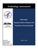
The GSP-type (gasification complex ‘black pump’)has
been developed in the 1970s in the Deutsches Brennstoff
Institut (DBI), Freiberg, East Germany, for the salt
(NaCl)-containing lignite from Central Germany, which
poses corrosion problems with alkali chlorides similar to
KCl-containing slag from fast-growing biomass
[29,31-33]. Figure 3 shows the simplified GSP gasifier
desi gn. The internal cooling screen is a gasti ght, welded
membrane wall of cooling pipes with a thin inner SiC
liner, particularly suited for low-quality biomass with
much low melting slag from KCl-containing ash. The
pipes are cooled with pressurized water at 200°C to 300°
C. A thin, ca. centimeter-thick, viscous slag layer covers
and protects the inner surface of the membrane wall
from corrosion and erosion. Only a small slag fraction
of a few percent escapes in the form of tiny, sticky dro-
plets with the raw syngas. In 1996, an experienced
development personnel designed and built an improved
3- to 5-MW(th) GSP pilot gasifier in Freiberg to test the
hazardous w aste conversion process of Noell Company
Dahmen et al. Energy, Sustainability and Society 2012, 2:3
/>Page 8 of 44
[34]. Experience with the GSP gasifier is the sound basis
of the KIT concept. The KIT bioslurry gasification con-
cept has been verified and investigated in this pilot gasi-
fier in four gasification campaigns in year 2002, 2003,
2004, and 2005 in cooperation with Future Energy,
today Siemens Fuel Gasification Technologies.
At KIT, a 5-MW(th) pilot gasifier with a cooled mem-
brane wall for a maximum of 80-bar pressure is pre-
sently being constructed as a part of the bioliq pilot
facility for the production of synthetic biofuels from bio-
mass. Substantial financial support has been granted by
FNR (German Ministry of Agriculture). Responsible for
the design, erection, and commissioning of the PEF pilot
gasifier with a membrane wall is Lurgi AG Company,
Frankfurt; start-up is expected in 2012.
Several companies have recognized the advantages of
slagging PEF gasifiers for biomass conversion to syngas;
Table 3 gives a brief overview. The main difference
between these process variants are the biomass pretreat-
ment steps. Pretreatment for PEF gasifiers requires more
technical effort than that for fixed or fluidized bed
gasifiers.
Figure 3 Scheme of a PEF gasifier with cooling screen.
Dahmen et al. Energy, Sustainability and Society 2012, 2:3
/>Page 9 of 44
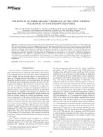
Outline of the bioliq
®
process
The bioslurry-based BTL process of KIT called bioliq is
described in more detail in the works of Henrich and
colleagues [18-27]. The simplified process scheme in
Figure 4 gives an overview.
Biomass preparation and fast pyrolysis
Sufficiently dry lignocellulo sic biomass like wood or
straw below ca. 15 wt.% moisture can be stored without
biologica l degradation. The dry biomat erials are diminu-
ted in two steps into small particles of < 3 mm in size.
The energy required for diminution is reduced at lower
moisture.
Biomass particles with a characteristic length of < 0.5
mm (sphere diameter, < 3 mm; cylinders, < 2 mm;
plates, < 1 mm) which are equivalent to a specific sur-
face of > 2,000-m
2
/m
3
biomass volume are mixed at
atmospheric pressure and at temperatures of ca.500°C
underexclusionofairwithanexcessofahot,grainy
heat carrier like sand or stainless steel (SS) balls
[27,35]. In principle, any fast pyrolysis (FP) reactor
type [36] can be applied. At KIT, an FP system with a
twin-screw mixer reactor is being developed, based on
the Lurgi-Ruhrgas system. The thermal decomposition
of biomass and the condensation of organic tar vapors
and reaction water vapors take place in the course of
one or few seconds. High condensate yields of 45 to
75 wt.% are coupled with low char and gas yields; this
is typical for FP. The char contains all ash; the solids’
yield depends on feedstock and operating conditions
and is in t he range between ca.10and35wt.%.The
pyrolysis gases contain CO and CO
2
as main compo-
nents in amounts between 30 and 55 vol.%; methane,
hydrogen, and hydrocarbons up to C
5
amount to ca.
10 vol.%. The heating value of the pyrolysis gas is
about 9 MJ/kg. The t otal energy content of the FP gas
corresponds to about 10% of the initial biomass HHV
and is sufficient to supply the thermal energy for a
well-designed FP reactor.
Production of bioslurries
FP char contains about 20% to 40% of the initial bioe-
nergy; the condensate (biooil), 70% to 50%, and together,
about 90%. If only the biooil is used for gasification
without the char, about one-third of the bioenergy
would not be accessible for syngas generation. There-
fore, the pyrolysis char powder is mixed into the biooil
to generate a dense slurry or paste with a density of
about 1,200 kg/m
3
andaHHVfrom18to25GJ/m
3
which corresponds to one-half up to two-thirds of the
volumetric energy density of heating oil (HHV 36 GJ/
m
3
) [37-39].
There are many good reasons for bioslurry produc-
tion: A single pyrolysis product with high energy density
eases handling, storage, and transport; a free-flowing
bioslurry can be conveniently pumped with little e ffort
into highly pressurized gasifiers. Even low-quality biooils
which are prone to phase separation and are contami-
nated with char and ash are still suited for bioslurry or
paste preparation. The fine, porous pyrolysis char pow-
ders from FP are very sensitive to self-ignition (self-igni-
tion temperature is typically > 115°C), and fine,
airborne, char dust particles can penetrate breathing
masks. Pulverized biochar usually is pelletized for safety
and handling reasons; slurries provide a much safer way
of char handling.
PEF gasification of bioslurries
Not only bioslurries and pastes, but also other dense
forms like char crumbs soaked with tar or pelletized
biochar can be transported in silo wagons with the
electrified rail from several dozens of regional pyrolysis
plants into a large, central biosynfuel plant for syngas
generation and use. PEF gasifica tion is a complex tech-
nology, and a large scale is required due to economy-
of-scale reasons. A suitable menu of bioslurries is pre-
heated with waste heat from the process to reduce the
viscosity and mixed in large vessels to obtain the
desired composition and is then further homogenized
Table 3 BTL developments using PEF gasifiers
Company/country Gasifier feed Gasification conditions Biomass pretreatment
Schwarze Pumpe/
Germany [29-33]
Diverse liquids, slurries from waste and
lignite
26 bar, 1,200°C to 1,600°C, GSP-
type, 130 MW(th)
Diverse lignite, organic waste
Choren/Germany
[5,91,92]
Hot pyrolysis vapors, char powder for
chemical quench
4 to 5 bar, > 1,400°C, char quench
to 900°C
Auto-thermal pyrolysis on-site at gasifier
pressure
Chemrec/Sweden [93,94] Concentrated black liquor ca. 40 bar, ca. 950°C Integrated into the on-site pulp mill
KIT, bioliq/Germany
[18-27]
Any bioslurry or paste from biooil plus
char
up to 80 bar, ca. 1,200°C FP at 500°C on- or off-site; any type of
biomass liquefaction
ECN/The Netherlands
[95,96]
Pulverized char from torrefaction ca. 40 bar, ca. 1,200°C Torrefaction (≤ 300°C pyrolysis on- or off-
site)
BioTFueL/France Pulverized char from torrefaction Uhde Prenflow™ gasifier, 15 MW
(th)
Torrefaction
KIT, Karlsruhe Institute of Technology; GSP, Gaskombinat Schwarze Pumpe; FP, fast pyrolysis.
Dahmen et al. Energy, Sustainability and Society 2012, 2:3
/>Page 10 of 44
in robust colloid mixers [40] during feeding. The pre-
heated slurry is transferred with screw or plunger
pumps into a highly pressurized PEF gasifier and pneu-
matically atomized in a special nozzle system with pure
oxygen. Gasification to a tar-free, low-methane syngas
proceeds in 3 to 4 s in a downward flame [16] at ≥
1,200°C above the ash melting point and at pressures
up to 100 bar. In a GSP-type gasifier [29], a viscous,
honey-like, ca. 1-cm-thick slag layer drains down at
the inner surface of a co oled membrane wall and pro-
tects the gasifier from erosion and corrosion. Gasifier
compatibility wit h the corrosive biomass ashes is an
essential characteristic. The high pressure slightly
above the downstream syntheses pressure eliminates
the high investment and operat ing costs for an inter-
mediate syngas compressor station and reduces the
Figure 4 Block flow diagram of the bioliq
®
process.
Dahmen et al. Energy, Sustainability and Society 2012, 2:3
/>Page 11 of 44
PEF reactor si ze. The pilot gasifier currently erected at
KIT can be operated at pressures up to 80 bar.
Cleaning and conditioning of the raw syngas
Syngas is a ‘platform chemical’ which can be used for
many different purposes: (1) combustion for a high-
temperature process of heat generation, (2) as fuel gas
in IGCC power stations, or (3) in small CHP plants
with stationary gas motors or turbines. Moderate gas
cleaning is required for these applications. Practically,
no syngas cleaning is needed for iron ore reduction. A
very efficient raw syngas cleaning and conditioning
section is needed prior to a catalyzed chemical synth-
esis [41]. Slag and soot particles, tars, alkali salts, and
gaseous S-, N-, and Cl-containing impurities like H
2
S,
COS, CS
2
,NH
3
,HCN,HCl,etc.havetoberemoved
down to below the part-per-million level to prevent
poisoning of the highly selective but sensitive catalysts.
The lower the catalyst temperature, the higher the
selectivity, but the sensitivity to impurities is also a
rule of thumb. Conventional technologies for gas
cleaning are available, e.g., the well-established Rectisol
process with methanol.
Most syngas reactions require an optimum H
2
/CO
ratio, which is usually obtained via CO conversion to H
2
with the catalyzed homogeneous shift reaction CO +
H
2
O ⇄ CO
2
+H
2
; a Fe/Cr cata lyst is applied for the
high-temperature shift at ca. 400°C, and a Cu/Zn cata-
lyst is applied for the low-temperature shift at ca. 200°C;
a sulfur-resistan t MoS
2
/Co cata lyst is suited at ca. 300°
C. CO
2
removal downstream is possible with a number
of absorbers; the conventional Rectisol process [41]
removes all higher boiling impurities by absorption in
cold methanol at ca. -50°C; this is a well-known and
very efficient but expensive technology, yet one of our
objectives is to look for process variants without the
necessity of an expensive CO shift. In addition, in the
pilot facility of the bioliq process, a hot gas cleaning sys-
tem is applied, consisting of a ceramic particle filter, a
fixed bed sorption for sour gas and alkaline removal,
and a catalytic reactor for the decomposition of organic
(if formed) and sulfur- and nitrogen-containing com-
pounds [42].
Syngas use
Clean syngas with the desired H
2
/CO ratio, temperature,
and pressure i s routed to one of the highly selective cat-
alysts for the production of H
2
,CH
4
,methanol
(CH
3
OH), DME, CH
3
OCH
3
, olefins, al cohols, FT hydro-
carbons, or other chemicals [43,44]. Synthesis selectivity
permits a flexible switch-over into different routes of
organic chemistry. E xcept H
2
production via the CO-
shift reaction, the synthesis of larger molecule s proceeds
under volume reduction, and higher pressures favor
product formation at equilibrium. Because of the order
increase i n the product molecules, the reaction entropy
Δ
r
S is negative, and lower temperatures shift the equili-
brium to the product side. At lower temperatures, more
active ca talysts are needed, which are more sensitive to
trace impurities and require more efficient gas cleaning;
also, a conversion of the reaction heat to power and
electricity becomes less efficient.
Mostsynthesisreactionswithsyngasarehighly
exothermal, and efficient heat removal is the main pro-
blem of the reactor design. The major reactor types are
tubular, staged, or slurry reactors with efficient coolers.
The immense literature on catalytic syngas conversion is
summarized in reviews [13,15], monographs [44], and
handbooks [14]. Reaso nable pathways to biosynfuels are
the FT synthesis and the methanol route [10,13,45]. The
FT product spectrum depends on the temperature (200°
C to 350°C), pressure (15 to 40 bar), reactor type, and
catalyst, usually Fe or Co, and extends from gaseous
CH
4
and C
2
-C
5
alkanes, a C
5
-C
9
gasoline, and a C
10
-C
20
diesel fraction of n-alkanes up to linear C
100
waxes. Fe
catalysts catalyze also the CO -shift reaction and allow
operation with H
2
/CO ratios below 2 in the feed gas. To
increase the biosynfuel yield, the C
25+
product waxes are
catalytically converted into gasoline and diesel in a
hydrocracker.
Present focus of the bioliq process is the production of
gasoline via DME (boi ling point (b.p.) 24°C) [46-48] as a
chemical intermediate to organi c chemicals and bi osyn-
fuels. Neat DME is suited as a clean and environmen-
tally compatible diesel fuel for cold climates. For the
one-step synthesis of DME in the bioliq process, a mix-
ture of a low-temperature Cu/ZnO/Al
2
O
3
methanol cat-
alyst and an alumina or zeolite dehydration catalyst is
used. Since the methanol catalyst also catalyzes t he CO-
shift reaction, a lower H
2
/COratioof1orevenbelow
offers the possibility of a cheaper syngas purification
train without CO shift. In addition, the high, thermody-
namic DME yields at higher pressure offer the possibi-
lity of a single-pass synthesis without expensive recycle
of unreacted syngas.
Based on t he considerations made above, a complete
BTL process chain is erected at KIT. The bioliq process
will be covered on the pilot plant scale in four succes-
sive proc ess sections, with the aim to dete rmine design
data for commercial facilities, to gain practical experi-
ence, to allow for reliable cost estimates, and for further
process development and optimization. The plant con-
sists of:
1. A 2-MW(th) (0.5 t/h), pilot-scale FP of lignocellu-
losic materials and biosyncrude preparation
2. Bioslurry PEF gasification up to 80 bar in a 5-MW
(th) pilot gasifier with a membrane screen
Dahmen et al. Energy, Sustainability and Society 2012, 2:3
/>Page 12 of 44
3. High-t emperature, high-pressure raw syngas
cleaning and conditioning, H
2
/CO ratio adjustment,
and CO
2
separation
4. Conversion of a ca. 700-Nm
3
synthesis sidestre am
to gasoline via DME with integrated CO shift
The FP plant is already in operation; the other three
plants are under construction with start-up expected in
2012. In the years to come, the present focus on biosynfuel
will gradually shift to chemical products. The status of the
KITbioliqpilotplantisreportedelsewhere[49,50].A
photo of the construction site is shown in Figure 5.
The f ollowing chapters expla in the conceptual design
and process f undamentals in essential details and the
resear ch and development status for the KIT bioliq pro-
cess in sequence of the successive process steps. Finally,
a cost estimate is presented.
Biomass preparation for FP
Any type of dry lignocellulosic biomass can be exploited
with the bioliq p rocess. The present experimental pro-
gram at KIT focuses on low-quality lignocellulosic bio-
mass, which is rarely used and still a vailable in larger
amounts in central Europe. This amounts to about half
of the cereal straw harvest which is not used and not
needed to maintain soil fertility. As a crude overall esti-
mate, it can be assumed that the average grain-to-straw
ratio i s about 1. The world grain harvest ( wheat, maize,
rice, and barley together ca. 90%) amounts to 2.2 Gt/a,
and t hus, about 1.1 Gt/a of surplus straw will be avail-
able, a significant energy equivalent of 0.4 Gtoe/a. Resi-
dues from the logwood (timber) ha rvest like bark, twigs,
and other forest residues can contribute a comparable
amount. The cost for cultivation and harvest of these
bio-residues is covered by the main products.
We have checked the conventional drying, diminution,
and heating processes for various biomate rials. Drying to
less than 15 wt.% water content is desirable to prevent bio-
logical degradation during storage. Up to now, we have
focused on a two-stage diminution of air-dry straw: first in
a usual chaff cutter followed by a hammer mill to smash
the several-millimeter-thick stalk nodes. Nodes come to
about 5% of the straw mass and increase the heat-up time
and reactor size for FP with the square of the particle size.
The typical wall thickness of cereal straw is about 0.3 mm
and corresponds to a specific surface of almost 7,000 m
2
/
m
3
. The reciprocal specific surface is the shape-indepen-
dent characteristic length of 0.15 mm. Diminution to a
single-walled straw material down to about 1 cm in length
is sufficient; further diminution is not desirable because it
does not change the characteristic lengths, and excess ive
diminution creates dust problems.
We also operate a shredder for the first diminution of
large pieces and a cutti ng mill for the second stage. The
latter turned out to be suited even with dump knives. A
hammer mill is also suited for the final diminution of
wood chips to below 3 mm. Due to the large variety of
biomaterials, there is no standard solution for optimum
diminution. Drying increases the brittleness and reduces
the energy consumption for diminution.
FP of lignocellulosic biomass
Previous work and conclusions
After the first oil price crisis in 1973, the development
of FP of lignocellulosic biomass was pushed mainly in
Figure 5 The bioliq
®
pilot plant construction site.
Dahmen et al. Energy, Sustainability and Society 2012, 2:3
/>Page 13 of 44
Canada, where huge forest resources and a low popula-
tion density create a high mass potential. Conversion of
wood in a simple, single step at a moderate temperature
of about 500°C into a stable and clean liquid fuel called
biooil was a charming idea [51,52]. The vision was to
replace part of the crude oil-derived heati ng oil and to
substitute a substantial part of the oil-derived motor
fuels not only for stationary applications, but hopefully
also for mobile internal combustion engines in passen-
ger cars, busses, and trucks. Today, three decades later,
no commercial biomass FP plant is in operation for
‘biooil’ motor fuel production. On t he contrary, most of
the FP pilo t plants which have been designed, built, and
operated for some time have been decommissioned or
mothballed. Reported reasons are low oil prices, high
biomass prices, poor biooil qualities in view to impuri-
ties, low chemical biooil stability, and phase separation.
Additional technical reasons are poor plant reliabilities
and availabilities.
Most FP investigations reported in the literature have
been conducted with ‘white’ wood without bark [53].
Relatively homogeneous and reasonably clean and stable,
single-phase biooils have been obtained from wood.
From ash-rich lignocellulosic materials like cereal straw
and other grassy biomass, we have obtained a lower
biooil quality and yield with higher water content, which
results in immediate or delayed phase separation into a
heavier tar phase and a lighter aqueous phase [35].
In practice, two different cond ensates are obtained by
a two-step condensation: First, a tar condensate at about
100°C with a few percent of water, which can solidify
already at tempera tures much above ambient. At about
ambient temperature, an aqueous condensate is
obtained with ca. 70 ± 15% water and various dissolved
organics and has a lower heating value (LHV) of usually
less than 5 MJ/kg [27]. Biooils with two phases are
unsuited for higher combustion applications: Biooil con-
tamination with pyrolysis char particles is another pro-
blem because all ash is contained in the char. Removal
of the fine char particles by filtration fails by filter plug-
ging and centrifugation by insufficient density
differences.
Compared to combustion, biooil quality requirement s
for PEF gasification in a GSP-type gasifier are much
lower. At least ca. 1 wt.% ash is even needed to generate
a protective slag layer at the inner surface of the gasifi-
cation chamber. Poor pyrolysis condensates with much
char and ash are therefore still suited for bioslurry pre-
parat ion and subsequent gasification. The pyrolysis char
increases the energy content of the biooil considerably
by 30% to 80%. Poor-quality lignocellulosics, e.g., ash-
rich agricultural residues like cereal straw, are still avail-
able as an almost unused biocarbon resource. They can
now be tapped and contribute substantially to the global
biocarbon potential. The lower quality requirements
connected with a change of biooil application from
combustion to gasification can help to simplify the FP
process.
Biomass pyrolysis as an independent process
FP of biomass can also be designed as an independent
process for the recovery of valuable py rolysis products
without integration into a biosynfuel production. Poten-
tial applications and recovery procedures for particular
pyrolysis products are reported in the literature [54].
Commercial applications are the production of f ood fla-
vorings (liquid smoke) and other fine chemicals as prac-
ticed, e.g., by Ens yn Company. A removal of a few mass
percent biooil constituents is not expected to jeopardize
bioslurry production for subsequent gasification. An
assumed profit of only €3/kg for 3 wt.% of reco vered
valuable biooil constituents might cover already all tech-
nical bioslurry manufacturing costs of ca. €50/t (see also
the ‘Economic aspects’ section). It is likely that such
opportunities are developed and commercially applied
in the future. A speculative extrapolation into an
extended and establishe d biorefinery future inv olves an
annual biooil production globally in a gigaton range.
Removal of minor constituents of a few per cent in
weight extends already into the ≥ 10-Mt/a production
range and can create a significant contribution to the
supply of organic specialty chemicals.
Reactor types for FP of biomass
Various reactor types are being investigated for FP of
biomass since about three decades [36,55] without a
clear champion; they are depicted in Figure 6. Most
types use an excess of a hot, grainy heat carrier - usually
1-mm quartz sand - heated to about 550°C, which is
quickly mixed wit h the dry (≤ 15% water) biomass,
diminuted to less than 3-mm grain size. FP takes place
in about 1 s, and the pyrolysis product gas, condensable
vapors, and small char particles are expelled from the
heat carrier bed in about 1 s. The heat carrier grains are
cooled down by ΔT =10to100Ktoafinaltempera-
ture of about 500°C and are then recycled and reheated
in a closed loop. The bulk of the fine pyrolysis char par-
ticles is carried with the hot pyrolysis gases and vapors
and is removed directly at the reactor exit in a hot
cyclone operated a t the FP reactor temperature of 500°
C. A minor char fraction is retained in the heat carrier
loop. With a well-designed and well -operated pyrolysis
reactor, char accumulation in the heat carrier loop
remains at an acceptably low level. Downstream from
the cyclone, the pyrolysis gases and vapors are usually
quenched to about ambient temperature by the injection
of a large stream of cooled condensate through nozzles.
Rapid quench cooling in a few seconds is essential to
prevent significant pyrolysis vapor decomposition and
maintains a high condensate yield. Quenching
Dahmen et al. Energy, Sustainability and Society 2012, 2:3
/>Page 14 of 44
techniques avoid the fouling of heat exchanger walls
with tar deposits. The disadvantage is that quench con-
densation does not allow efficient heat recovery.
The most common reactor type is a bubbling fluidized
bed with ca.1-mmquartzsand[36,55].Coldpyrolysis
gas downstream from the quench condenser must be
recycled for bed fluidization. Pyrolysis vapor dilution
with non-condensable gases increases the undesired
energy loss during quench condensation and requires a
larger and more expensive condensation system.
A ci rculating fluidized bed requires even more fluidiz-
ing gas. Ensyn Company successfully operates such 2-t/
h FP reactors since many years on a commercial scale,
but different to optimum syngas generation, the energy
efficiency is not an important aspect for their produc-
tion of fine chemicals and food flavorings.
The rotating cone reactor [56 ,57] and the twin-screw
mixer reactor [58] use a hot heat carrier loop with a
mechanically fluidized b ed without an auxiliary fluidiz-
ing gas. This reduces the size of the biooil condensation
system, but especially somewhat higher flow fluctuations
and reduced char removal efficiency in the cyclone must
be considered. Vacuum operation at ca. 0.1 to 0.2 bar is
another more general method [59], which can be
applied in all process versions t o reduce the gas and
vapor residence time. However, technology becomes
more complex, and control of air in leakage is an addi-
tional safety aspect, which usually is prevented by a
slight overpressure. Pyrovac Company, Canada has dis-
continued pilot plant operation because of finan cial
problems. The state of development of ablative pyrolysis
is relatively low, especially in view to scale-up [60] . The
ceramic ball-heated downflow tube reactor, developed at
Shandong University of Technology, China, deserves
attention because of its simple design and operation
[61].
The twin-screw mixer reactor
The t win-screw mixer (TSM) reactor was chosen
because it was already applied on a technical scale for
FP of other materials like coal, oil refinery residues, or
oil shale [58]. Technology development started in the
1950s with a collaboration of Lurgi and Ruhrgas Com-
panies for the so-called Lurgi-Ruhrgas (LR)-mixer reac-
tor for coal pyrolysis for town gas production [62]. If
the TSM reactor turns out to be suited also for FP of
biomass, it is expected that the available industrial
experience will contribute to reduce time and cost of
further development to a commercial scale. This practi-
cal aspect does not necessarily mean that design and
operating principles of the TSM are superior to the
other FP reac tors. Any type shown in Figure 6 is princi-
pally suited to prepare a bioslurry for PEF gasification.
Also, the pyrolysis product yield structure is not
expected to be much different. Final selection criteria
will be based on costs, safety, reliability, and plant avail-
ability, which depend much on the FP reactor periphery.
Design characteristics of the TSM reactor are two
intertwining and speciall y shaped screws, rotating in the
same sense and cleaning each other as well as the inter-
nal reactor su rfaces. Design and operating principles are
Figure 6 Reactor types used for fast pyrolysis of biomass.
Dahmen et al. Energy, Sustainability and Society 2012, 2:3
/>Page 15 of 44
outlined in Figure 7. The grainy material is transported
axially and mi xed radially. A suitable rotation frequency
ν is at a Froude number of 1. This means that the cen-
trifugal force 2π
2
·m·d ν
2
at the outer screw radius equals
the weight m·g. This creates fluidization, which consid-
erably eases transport and mixing. The level in the reac-
tor increases in proportion with the throughput and is
usually kept at less than half to prevent plugging.
At typical residence times in the order of about 10 s,
thereactorsurfaceistoosmalltosupplytheheatfor
pyrolysis through the wall. A surplus of a hot, grainy
heat carrier material, e.g., quartz o r SiC sand, ceramic
grains,orSSballs,istherefore quickly mixed with the
cold diminuted biofeed. To ensure a rapid pyrolytic
decomposition, the particle size of heat carrier and bio-
feed must be small enough to expose a sufficiently large
surface for heat transfer. A desira ble heat ca rrier/feed
ratio on a volume basis is about 2; this means that the
empty space between the heat carrier grains of about
40% of the total bed volume is filled with the bulky
dimin uted biofeed. Since the biomass volume shrinks to
about half during pyrolysis, about equal bulk volumes
are a reasonable maximum at start. With a bulk density
of 4,800 kg/m
3
for steel balls and 100 kg/m
3
for un-pyr-
olyzed straw chops, about 50 kg of steel balls will be cir-
culated per kilogram of biomass. This is the design ratio
in our FP-process development unit (PDU). All pyrolysis
gases, vapors, and fine char particles are expelled in a
cross-flow direction from the shallow reaction bed.
Rapid removal and quench condensation of the pyrolysis
vapors is esse ntial to prevent thermal vapor decomposi-
tion at the surfaces of the hot heat carrier grains and
maintains high condensate yields.
Pyrolysis facilities at KIT
Lab-scale fluidized bed
For q uick screening tests of the FP behavior of various
biomaterials, a lab-scale device with a bubbling fluidized
sand bed for a maximum of 0.3 kg/h of throughput has
been built (Figure 8). The reactor is 4 cm in diameter
and is filled 12 cm high with ca. 0.2-kg, 0.2- to 0.3-mm-
diameter quartz sand and fluidized with 1 m
3
(standard
temperature and pressure (STP))/h preheated nitrogen.
A pre-weight amount of ca. 0.5 kg of diminuted biomass
is constantly fed into the fluidized bed with a screw fee-
der together with a slight nitrogen stream to prevent
Figure 7 Principle of the twin-screw mixer reactor.
Dahmen et al. Energy, Sustainability and Society 2012, 2:3
/>Page 16 of 44
backflow of pyrolysis gas. The pyrolysis reactor and the
subsequent char cyclone are mounted in an electrically
heated oven. Product recovery is conventional via a hot
cyclone and a two-stage condenser with an electr ostatic
precipitator. At the end, the mass of char, condensate,
and gas is determined and analyzed.
Process development unit
In 2002 to 2003, a PDU with a TSM reactor for a
throughput of 10 to 20 kg/h of biomass has been
designed and built at the KIT to test the suitability of
the twin-screw reactor type for FP of biomass [26]. A
simplified flow s heet is shown in Figure 9. The major
plant sections are briefly described.
• Hot heat carrier loop. A grainy heat carrier circu-
lates at a temperature of about 500°C in a closed,
gastight loop with a single exit for all pyrolysis pro-
ducts. Various heat carriers either 1-mm sand or SiC
grains or 1.5-mm SS balls are lifted vertically 3 m
with a conventional bucket elevator made from SS.
The h eat carrier material is reheated by ΔT = 10°C
to 100°C during gravity flow through a 1-m-high,
coaxial twin cylinder with a diameter of 0.15 m and
a1-cm-wideannulargap,heated electrically from
both sides via a 1-m
2
surface. A volume-calibrated,
controlled screw feeder transports a constant heat
carrier stream into the pyrolysis reactor, at a maxi-
mum of either 0.4-t/h, 1-mm quartz (bulk density
1,500 kg/m
3
) or SiC sand or 1.5- to 2-mm SS balls
up to 1.5 t/h (bulk density 4,800 kg/m
3
). A second
screw feeder controls the biomass feed rate of 10 to
20 kg/h. Main construction material in the hot loop
section is SS, which turned out to be suitable.
• TSM react or. The active length of the twin-screw
reactor is 1 m; the inner and outer screw diameters
are 2 and 4 cm, respectively; and the pitch is 0.2 m
(see Figure 8). A typical rotation fre quency is ca.3
Hz (Froude number almost 1). The heat carrier
mean residence time in the reactor of ca.10sis
almost independent from the heat carrier flow as
long as the heat carrier level is below about half.
Kinetic measurements have shown that this time is
sufficient for FP. Figure 10 shows that the pyrolysis
rate for < 2-mm wood particles are faster, especially
for cereal straw which has a wall thickness of only
0.3 mm (0.15 mm characteristic length). From the
bulk volume flow rate at typical operating condi-
tions, it has been estimated that the reac tor volume
Figure 8 Laboratory-scale FP device.
Dahmen et al. Energy, Sustainability and Society 2012, 2:3
/>Page 17 of 44
is usually filled up to only less than half, a suffi-
ciently low level to prevent plugging.
• Product recovery system. The normal product
recovery system consists of a hot cyclone operated
at a reactor temperature of 500°C to remove the
bulk of the entrained char particles. This is comple-
men ted by a subsequent quench cond enser for flash
condensation of tars and reaction water by the
recycle and injection of a cooled quench condensate.
In the KIT PD U, this system is frequently modified
and tested in an iterative process to find the best
way for a reliable recovery operation.
Trouble with solid deposits can arise if sticky tars con-
dense at the walls and collect char powder from the gas
stream. At higher t emperatures, the soft deposits
decompose gradually to a hard, black, and highly porous
material. Automatic or occasional mechanical removal
of potential depos its is advisable at few critical sites to
maintain a reliable continuous operation without inter-
ruption. The flow s heet in Figure 9 shows the actual
test version for product recovery: after quick cooling to
ca. 100°C in the presence of char, char crumbs are
remov ed with condensed tar soaked and eventually soli-
dified in the pore system. The more or less solidified tar
in the pores deactivates the char and prevents self-igni-
tion and char dust inhalation during handling.
Lurgi’s Mini-LR plant
In addition to the oper ation of the KIT PDU, we have
performed a n experimental campaign at the 3- to 5-kg/
h Mini-LR plant of Lurgi Company in Frankfurt. The
main diffe rence of the two facilities shown in the photos
of Figure 11 is the design of the heat carrier loop, as
outlined in Fi gure 12. Heat carrier in the Mini-LR plant
is 1-mm quartz sand. It is lifted pneumatically with hot
flue gas from pyrolysis gas combustion with air and
simultaneously reheated to a maximum temperature of
600°C in direct contact with excellent heat transfer.
Because the flue gas has been in contact with pyrolysis
residues in the heat carrier sand and is afterwards
released into the atmosphere, the system is open to the
environment and needs careful gas cleaning especially
after contact with the char-contaminated heat carrier
grains. To prevent the intrusion of the slightly pressur-
ized lift gas into the pyrolysis reactor, it must be sepa-
rated above and below by the flow resistance of a
longer, sand-filled, pipe section of several meters in
length. This increases the height and cost of the expen-
sive hot loop section. S and particle attrition must also
be considered because of the high velocities of almost
Figure 9 Flow sheet of the FP PDU.
Dahmen et al. Energy, Sustainability and Society 2012, 2:3
/>Page 18 of 44
20 m/s in the lift pipe. Successful industrial experience
is claimed for this version.
FP pilot facility at Karlsruhe
Mid-2005, after experimental confirmation of the principal
suitability of the TSM reactor for biomass FP in the small
KIT and Lurgi FP facilities and after four successful bio-
slurry gasification campaigns in the 3- to 5-MW(th), GSP-
type, PEF pilot gasifier at a 26-bar pressure with up to 0.6
t/h (3 MW(th)) of bioslurry throughput (see the ‘Bioslurry
gasification’ section), it has been decided to extend also
the small-scale FP investigations to the pilot plant scale to
determine design data for a FP demonstration plant.
A 0.5-t/h FP pilot plant (2 MW(th)) based on Lurgi’s
industrial experie nce [63] with sand as heat carrier and
a pneumatic lift in an ‘open loop’ version has been built
up at KIT . A simpl ified flow sheet is shown in Figure
13. Figure 14 shows a photo, and in the study of Dah-
men [64], a brief description is given. The plant is in
operation since 2010 in test campaigns of typically 1
week in duration using straw as the feed material.
Experimental results and operating experience
Typical operation conditions
Meanwhile, the accumulated operating experience for
FP of biomass in the PDU amounts to more than 2,000
h of operation with more than 100 individual runs and
more than two dozens of different biomass types, e.g .,
hardwood, softwood, wheat, maize, straw, rice straw,
hay, miscanthus, bran, different oil palm residues, sug ar
cane bagasse, etc. A typical run starts with the preheated
facility and the heat carrier circulating in the loop at the
correct operat ing temperature and circulation rate. At a
feed rate of 10 to 20 kg/h of dry diminuted biomass, it
takes several hours until a carefully pre-weight total
amount of 40 to 80 kg of biomass is fed at a constant
rate into the pyrolysis reactor. Several hours of steady-
state operation turned out to be sufficient to get a rea-
sonably accurate mass and energy balance for the solid,
liquid, and gaseous products, whose percentages and
properties are needed for the subsequent slurry prepara-
tion and gasification steps.
Char, condensate, and gas yields
A typical example of yield results for a FP campaign
with a total of 19 runs for four different feedstocks is
summarized in Figure 15[35]. The bars represent the
average yields of three to seven identical runs for e ach
feedstock. The same type of results is shown in Figure
16 for an experimental campaign in the Mini-LR plant
of Lurgi Company, Frankfurt, performed in collabora-
tion with KIT [26]. The results are consistent within the
Figure 10 Pyrolysis kinetics of wood and straw.
Dahmen et al. Energy, Sustainability and Society 2012, 2:3
/>Page 19 of 44
Figure 11 Photos of the FP PDU at KIT (left) and of Lurgi’s Mini-LR plant (right).
Figure 12 Essential differences of the KIT and Lurgi FP heat carrier loop concepts.
Dahmen et al. Energy, Sustainability and Society 2012, 2:3
/>Page 20 of 44
error range. The mass yields of the liquid condensates
from wood pyrolysis are three to four times higher than
those of ch ar and are more than sufficient to produce a
free-flowing bioslurry (see the ‘Bioslurry preparation’
section). The yield of p yrolysis liquids from straw is
much lower and only about twice the mass of char. At
the expense of lower condensate yields, pyrolysis gas
and char as well as the reaction water yields for straw
Figure 13 Simplified flow sheet of the FP pilot plant at KIT.
Figure 14 Photos of the 0.5-t/h FP plant at KIT.
Dahmen et al. Energy, Sustainability and Society 2012, 2:3
/>Page 21 of 44
are about 1.5 times higher t han those for wood. The
amount of reaction water plus moisture in the conden-
sates has been determined by Karl Fischer titration.
The stability o f pyrolysis condens ates towards phase
separation into a heavy tar phase and a lighter aqueous
phase decreases with increa sing water c ontent. Above
Figure 15 FP product yields for different types of biomass (KIT PDU) [35].
Figure 16 FP product yields for different types of biomass (Lurgi’s Mini-LR plant).
Dahmen et al. Energy, Sustainability and Society 2012, 2:3
/>Page 22 of 44
30 to 35 wt.% water, phase separation occurs almost
immediately after condensation; we could never obtain a
stable biooil from air-dry cereal straw. Even for some
initially homogeneous biooil phases from wood with
around 25 wt.% water, we have observed a delayed
phase separation after several weeks or months.
Pyrolysis gas composition
The typical composition of FP gases is shown in F igure
17. Main constituents are CO
2
and CO. The minor con-
stituents H
2
,CH
4
, and the gaseous hydrocarbons (C
2
-C
5
alkanes and alkenes) contribute about half to the heating
value. Vapors of very volatile CHO constituents like for-
maldehyde, acetaldehyde, acetone, methanol, glyoxal,
methyl, ethyl esters of formic and acetic acids, etc. can
escape with the gases, but have not been analyzed in
detail so far. They are suspected to be responsible, at
least partly, for the typical mass balan ce deficit of sev-
eral percent observed when all measured constituents
are summarized. Thus, a simple increase of the final
condensation temperature can increase the energy con-
tent in the pyrolysis gas. Thus, an i n-line control of the
condensation temperature can be used to adjust the
energy content in the pyrolysis gas exactly to the
demand for a self-sustained process.
Heat required for FP
Much effort has been devoted determining the specific
heat required for FP. The reaction enthalpy (Δ
r
H)ofan
exo- or endothermal pyrolysis reaction must be sub-
tracted from the sensible heat required to heat the pyro-
lysis products from ambient to 500°C. The higher the
yield of the combustion products CO
2
,H
2
O, or the
related char product in reaction 1 below, the more
exothermal the pyrolysis reaction becomes. This can be
illustrated with the idealized pyrolysis reactions in Table
4, using the experimental he at of combustion (Δ
c
H)of
lignocellul ose with the simplified formula C
3
H
4
O
2
(Δ
c
H
(= HHV) = -1,402 kJ/mol (according to the Channiwala
relation [63]), Δ
c
H = 1,4 60 kJ/mol (experimental)) and
the tabulated heats of combustion for the products.
A self-sustained slow pyrolysis of compl etely dry, pre-
heated wood in a rotary kiln was practiced commercially
at Ford Motor Company until the 1930s [7,65]. For FP
with much lower char, CO
2
, and water yields, a thermo-
neutral or even endothermal pyrolysis reaction is more
likely and depends on the product composition. The
Channiwala relation overestimates the HHV of CO
2
,
H
2
O, and char. In reality, the HHV of products are
higher (less negative) and push Δ
r
H towards a more
endothermal value.
In the P DU, the o verall heat consumption has been
measured experimentally for various biomaterials. The
amount of heat consumed for p yrolysis corresponds to
the heat removed from the heat carrier, which is the
known product of the heat carrier flow rate
·
m
(in
Figure 17 Typical composition of FP gas (complement to Figure 16).
Dahmen et al. Energy, Sustainability and Society 2012, 2:3
/>Page 23 of 44
kilograms per second), the specific heat at reaction tem-
perature c
p
(ca. 0.7 kJ/kg K for SS at 500°C), and the
temperature difference ΔT between the reactor inlet and
exit. In a small facility, the simultaneous heat in- or out-
flow through th e reactor insulation must also be consid-
ered. The heat required for the pyrolysis of 1 kg of
biomass is obtained by division with the biomass feed
rate in kilograms per second. Figure 18 shows an exam-
ple for the temperature drop ΔT in the reactor during a
4-h, stationary-state operation (60 to 300 min) in a typi-
cal run with a constant of 1.14-t/h SS ball heat carrier
circulation at a 9.5-kg/h hardwood feed rate.
A mean heat consumption of 1.3 ± 0.4 MJ/kg for FP
has been measured for dry lignocellulosics [35].
Daugaard [66] has reported a range of 0 .8 to 1.6 M J/kg
for FP for various lignocellulosics. This corresponds to
about 7 ± 2% of the initial bioener gy. For moist materi-
als, the value is somewhat higher since water needs 3.4
MJ/kg for heat-up from 20°C to 500°C. Antal and Gronli
[67] have reported an about linear increase of the liber-
ated re action heat with increasing char yield with ther-
moneutrality in the range of about 20% char yield.
Together with some thermal insulation losses, a con-
sumption of ca. 10% of the bioenergy is therefore
expected for FP in practice. The pyrolysis gases contain
6% to 10% of t he initial bioenergy without volatile oxy-
genates, and their combustion should supply sufficient
energy for FP, at least at a somewhat higher final con-
densation temperature. Thus, all char and condensates
remain available for bioslurry preparation, and there is
no process waste except the flue gas from pyrolysis gas
combustion. At the end, the pyrolysis gas is washed
with the aqueous pyrolys is condensate and will be rela-
tively clean.
Quartz sand and SS balls as heat carriers
We have experimentally compared 1-mm quartz and
SiC sand and 1.5-mm SS balls as heat carrier materials.
The essential experience is that the SS balls are superior:
The throughput of the PDU could be increased by at
least 50%, and the availability of the facility and the
reliability of operation could b e improved considerably.
Table 4 Reaction enthalpy of idealized pyrolysis reactions
Pyrolysis Reaction Δ
r
H (kJ/mol)
Exothermal pyrolysis
Reaction 1 C
3
H
4
O
2
® 3C + 2H
2
O -278
Reaction 2 C
3
H
4
O
2
® C+CH
4
+CO
2
-196
Endothermal pyrolysis
Reaction 3 C
3
H
4
O
2
® C + 2CH
2
O76
Δ
c
H (HHV; kJ/mol)
CCH
4
CH
2
OH
2
OCO
2
Known from tables -394 -890 -571 0 0
Channiwala estimate -419 -895 -491 -72 -89
Δ
c
H, heat of combustion; HHV, higher heating value; Δ
r
H, reaction enthalpy.
Figure 18 In- and outlet temperatures of SS ball heat carrier.
Dahmen et al. Energy, Sustainability and Society 2012, 2:3
/>Page 24 of 44
The small amount of attrited fine sand, especially from
SiC particles, caused some erosion in downstream
pumps. The SS balls did not show attrition; after 1,000
h of o peration, the mass of several hundreds of clean
steel balls did not change within error, a hint to low
wear and tear.
Modeling of lignocellulose FP
The optimum FP temperature of ca. 500°C for lignocel-
lulose is in the range where C-C bonds can form and
break simultaneously. The decomposition of the biopo-
lymer structures by F P creates a complex multitude of
hundreds of different solid, liquid, and gaseous carbon
specie s. We do not rely on any speculations concerning
macro-kinetic reaction mechanisms to predict the
lumped yields of char, organic condensate, reaction
water, and gases for the various lignocellulosic bio-feed-
stocks in this complex system. Based on literature data
and our own experiments, we have decided for a rather
primitive and oversimplified yield prediction model for
FP of lignocellulose at atmospheric pressure and at 500°
C in a well-designed FP reactor. Lignocellulosic materi-
als are divided into only two groups according to their
ash content: < 2 wt.% (e.g., wood) and > 2 wt.% (e.g.,
straw). The lumped product yields for the water and
ash-free lignocellulosic CHO fraction are given in Table
5.
For a moist lignocellulose with ash, the ash must be
added to the char, and the moisture, to the reaction
water or the condensate. For the yield percentages
related to the real material, the corrected numbers must
be normalized to 100%. For highly ash-containing ligno-
cellulose like straw, the char, gas, and reaction water
yields increase by a factor of roughly 1.5, at the expense
of the much lower tar yield. This can be explained by
catalytic tar vapor decomposition at the ash and char
surfaces. The relatively large yield fluctua tions observed
in practice indicate that the co ntrolling feed properti es
and operating conditions are not yet completely under-
stood. Table 5 is helpful to get a rough first estimate
without much effort; experimental confirmation must
follow.
Scale-up of the TSM reactor
Eight LR mixer reactors have been built by Lurgi Com-
pany, Frankfurt up to a 1-m screw diameter and 600-
m
3
/h heat carrier circulation [58]. Reliable scale-up rules
based on similarity criteria [68] have been developed by
Peters [62]. The volumetric feed rate
•
V
and reactor
volume V should scale with the outer screw diameter d
according to the following equation: V
1
/V
2
=(d
1
/d
2
)
2.5
.
An extreme and therefore lessreliableextrapolation
from a small 20-kg/h design in the PDU to 20 t/h in a
large commercial plant corresponds to a 1,000-fold feed
rate increase and an about 16-fold increase of a 0.04-m
screw diameter to ca.0.64manda
√
16
-fold screw
length increase from 1 to ca. 5 m. A screw pitch of 2.5
m corresponds to a length/diameter ratio of 4. At a
Froude number of 1, the rotati on frequency in the 20-t/
h plant is n = g/(2π
2
d)
1/2
=1.15Hz.Ata12-smean
residence time and a 1,000-t/h SS ball circulation (ca.
210 m
3
/h or ca.0.06m
3
/s), the ball inventory is about
0.36 m
3
or ca. 30% of the reactor volume.
Per kilogram of lignocellulose, 50 kg of SS balls are
circulated, which requires 1.3 ± 0.4 MJ of heat. With
the specific heat for SS of 0.7 kJ/kg·K at 500°C, a heat-
up of ΔT = 37 K is needed for 1.3 MJ. In view to some
thermal loss, a temperature difference of at least 40 K
seems reasonable; to cover extreme situations, a design
value of about ΔT = 50 K is advisable.
A twin-screw reactor with corrosion-resistant Incoloy
800 plated screws and a refractory liner at the reactor
wall represents ≤ 10% of the total capital investment
(TCI) fo r a FP plant. The remaining design and operat-
ing problems are expected to be proportional to the
remaining capital expenditure (capex) of 90%, and
potential problems arising in the reactor periphery
should therefore not be underestimated. This statement
is amplified by the fact that experience from large tech-
nical FP plants with the desired capacit y does not exist;
their state of development is the lowest in the bioliq
process chain.
Bioslurry preparation
Gasifier feed preparation options
The aim of the bi oslurry gasification concept is the pre-
paration of a convenient feed fo r a large PEF gasifier.
For this p urpose, it is unimportant if the FP plants are
colocated at the gasifier site or distributed in the region.
The latter option is attr activesincethedensepyrolysis
slurries or pastes are suited for easy handling, compact
storage, and cheap transport, which favor the erection of
a large and more economic central BTL plant. Optimum
Table 5 FP yield prediction for lignocellulose given on a water- and ash-free basis
Ash content Solid Liquids Gas Sum (%)
Char (wt.%) Tar (wt.%) Reaction water (wt.%) Gas (wt.%)
Low, < 2% (e.g., wood) 16 56 12 16 100
High, > 2% (e.g., straw) 24 34 18 24 100
Dahmen et al. Energy, Sustainability and Society 2012, 2:3
/>Page 25 of 44