A Practical Introduction to OPtical Mirieralogy ppt
Bạn đang xem bản rút gọn của tài liệu. Xem và tải ngay bản đầy đủ của tài liệu tại đây (21.84 MB, 131 trang )
TITLES
OF
RELATED
INTEREST
Rutley's elements
of
mineralogy, 26th edn
H.
H.
Read
Petrology
of
the igneous rocks, 13th edn
F. H. Hatch, A. K. Wells &
M.
K.
Wells
Metamorphism and metamorphic belts
A. Miyashiro
Metamorphic processes
R. H. Vernon
Petrology
of
the metamorphic rocks
R. Mason
The
interpretation
of
igneous rocks
K.
G. Cox,
J.D.
Bell & R. J. Pankhurst
The inaccessible Earth
G.
C.
Brown & A. E. Mussett
Metamorphic geology
C.
Gillen
The poetry
of
geology
R.
M.
Hazen
(ed.)
Komatiites
N. T.
Arndt
& E. G. Nisbet (eds)
Geology and man
J. Watson
Geological howlers
w. D.
I.
Rolfe (ed.)
Statistical methods in geology
R.
F. Cheeney
Field mapping for geology students
F.
Ahmed
& D.
C.
Almond
The dark side
of
the Earth
R. Muir Wood
Geology and mineral resources
of
West Africa
J.
B. Wright
et
at.
Petroleum geology
F. K.
North
A
Practical
Introduction
to
OPtical
Mirieralogy
C.D
Gribble
Department
of
Geology, University
of
Glasgow
A.J.
HaJJ
Department
of
Applied
Geology, University
of
Strathclyde
Lo
nd
on
GE
ORG
E
AL
LEN &
UN
WIN
Boston
Sydney
o
C.
D. Gribble and A. J. Hall, 1985
This book
is
copyright under the Berne Convention. No reproduction
without permission. All rights reserved.
George Allen
& Unwin (Publishers)
Ltd,
40
Museum Street, London WCIA
lLU,
UK
George Allen & Unwin (Publishers) Ltd,
Park Lane, Heme! Hempstead, Herts HP2
4TE
, UK
Allen
& Unwin Inc.,
8 Winchester Place, Winchester, Mass. 01890,
USA
George Allen & Unwin Australia Pty Ltd,
8 Napier
Street, North Sydney, NSW 2060, Australia
First published
in
1985
British Library Cataloguing in
Publication Data
Gribble,
C.
D.
A practical introduction to
opt
ic
al mineralogy.
1. Optical mineralogy 2. Microscope and microscopy
I.
Title II. Hall, A. J.
549'.125
QE369
.06
ISBN 0-04-549007-4
ISBN 0-04-549008-2 Pbk
Library of Congress Cataloging in Publication Data
Gribble
C.
D.
A practical introduction to optical mineralogy.
Bibliography:
p.
Includes index.
1. Optical mineralogy. I. Hall, A. J. II. Title.
QE369
.06G75 1985 549' .125 84-28404
ISBN 0-04-549007-4 (alk. paper)
ISBN 0-04-549008-2
(pbk.:
alk. paper)
Set
in
9 on
11
point Times by
D
.P.
Media Limited, Hitchin, Hertfordshire
and printed
in
Great
Britain
by
Butler & Ta
nner
Ltd, Frome and London
Preface
Microscopy
is
a servant
of
all
the
sciences,
and
the microscopic examina-
tion
of
minerals
is
an important technique which should be mastered by
all students
of
geology early in their careers. Advanced
modern
text-
books on both optics and mineralogy
are
available, and
our
intention
is
not
that
this new
textbook
should replace these
but
that
it should serve
as an introductory text
or
a first stepping-stone to
the
study
of
optical
mineralogy.
The
present
text has been written with full awareness
that
it
will
probably be used as a laboratory
handbook
, serving as a quick
reference to the
propertie
s
of
minerals,
but
nevertheless care has been
taken to present a systematic explanation
of
the
use
of
the
microscope
as
well as theoretical aspects
of
optical mineralogy.
The
book
is
therefore
suitable for
the
novice either studying as an individual
or
participating
in
cl
asswork.
Both
transmitted-light microscopy
and
reflected-light microscopy are
dealt with, the
former
involving examination
of
transparent
minerals in
thin section
and
the latter involving examination
of
opaque
minerals
in
polished section. Reflected-light microscopy
is
increasing in importance
in
undergraduate courses on
ore
mineralisation, but
the
main reason for
combining the two aspects
of
microscopy
is
that
it
is
no longer acceptable
to neglect
opaque
minerals in the systematic petrographic study
of
rocks. Dual purpose microscopes incorporating transmitted- and
reflected-light modes are readily available, and these are ideal for
the
study
of
polished thin sections.
The
technique
of
preparing polished thin
sections has been perfected for use
in
the electron microprobe analyser,
which permits
ana
lysis
of
points
of
the
order
of
one
micron
diameter
on
the polished surface
of
the section. Reflected-light study
of
polished thin
sections
is
a prerequisite
of
electron microprobe analysis, so an ability to
characterise minerals
in
reflected light
is
of obvious advantage.
Reflected-light microscopy
is
described with consideration
of
the
possibility
that
experienced transmitted-light microscopists may wish to
use this book as an introduction to
the
reflected-light technique.
This book
therefore
introduces
students
to
the
use
of
both
the
transmitted-
and
reflected-light microscope
and
to
the
study
of
minerals
using both methods (Ch. 1).
The
descriptive section on minerals
is
subdivided for ease of presentation:
the
silicates (which
are
studied
u
si
ng transmitted light) are described in
Chapter
2,
and
are
followed in
Cha
pter
3 by
the
non-silicates (which
are
studied using either transmit-
ted or reflected light).
The
minerals
are
presented in alphabetical
order
but, to save duplicating descriptions, closely related minerals have been
presented
together
.
The
best way to locate the description
of
a given
mineral
is
therefore to look up the required mineral
in
the
index, where
minerals
appear
in alphabetical order. Although important, a detailed
understanding
of
optical theory
is
not essential to mineral identification.
vii
ACKNOWLEDGEMENTS
Accounts of transmitted-light optical crystallography and reflected-light
theory are therefore placed after the main descriptions of minerals,
in
Chapters 4 and 5 respectively.
The
appendices include systematic lists of
the optical properties of minerals for use
in
identification.
This book
is
intended to be an aid to
the
identification
of
minerals
under the microscope, but not to the description
or
interpretation
of
mineral relationships. We both hope
that
the text
fills
its intended slot,
and
that
students find it helpful and enjoyable to use.
Acknowledgements
The sections dealing with transmitted light have been written by
C.
D.
Gribble.
He
acknowledges the debt owed to Kerr (1977), whose format
has generally
been
employed
in
Chapter 2, and
to
Deer
et al. (1966),
whose sections on physical properties and mineral paragenesis have
often been the basis of the
RI
values and occurrences given
in
this text.
Other
authors and papers have been employed,
in
particular Smith
(1974) on the feldspars and Wahlstrom (1959) on optical crystallo-
graphy.
Descriptions
of
the opaque minerals by A. J. Hall are based on
data
in
many texts. However, they are taken mainly from the tables of Uyten-
bogaardt and Burke
(1971), the classic text Dana's system
of
mineralogy
edited by Palache et al. (1962), the unsurpassed description
of
the
textures
of
the ore minerals by
Ramdohr
(1969), and the atlas by Picot
and Johan
(1977).
The
textbook on the microscopic study of minerals by
Galopin and
Henry
(1972), and course notes and publications
of
Cervelle, form the basis of the section on theoretical aspects of
reflected-light microscopy.
The
Michel-Levy chart
on
the back cover
is
reproduced with the kind
permission
of
Carl Zeiss
of
Oberkochen, Federal Republic
of
Germany.
We are grateful for support and suggestions by
our
colleagues in the
Universities of Glasgow and Strathclyde. A special thanks
is
due
to
the
typists
Janette
Forbes, Irene Wells, Dorothy Rae,
Irene
Elder
and
Mary
Fortune.
Also,
we
are particularly grateful to
John
Wadsworth and Fergus
Gibb for their comments and reviews
of
the original manuscript, and to
Brian Goodale for his comments on
Chapter
4.
Any errors
or
inaccuracies are, however, ours.
viii
Contents
Preface
Acknowledgements
List
of
tables
page vii
viii
xi
List
of
symbols and abbreviations used in
text
xii
1
2
ix
Introduction
to
the
microscopic
study
of
minera
ls
1.1 Introduction 1
1.2
The
transmitted-light microscope 1
1.3
Systematic description of minerals
in
thin section
using transmitted light 5
1.3.1 Properties
in
plane polarised light 5
1.3.2
Properties
under
crossed polars 8
1.4
The
reflected-light microscope 12
1:5
The
appearance
of
polished sections
under
the
reflected-light microscope
17
1.6
Systematic description
of
minerals
in
polished section
using reflected light
19
1.6.1
Properties observed using plane polarised
light (PPL)
19
1.6.2
Properties observed using crossed polars 20
1.6.3
The
external nature
of
grains
21
1.6.4 Internal properties
of
grains
21
1.6.5 Vickers hardness
number
(VHN)
22
1.6.6
Distinguishing features 22
1. 7
Observations using oil immersion
in
reflected-light
studies
22
1.8
Polishing hardness 23
1.9
Microhardness
(VHN)
25
1.10 Points
on
the use
of
the microscope (transmitted
and
reflected light) 26
1.11
Thin- and polished-section preparation 28
Silicate minerals
2.1 Crystal chemistry
of
silicate minerals 30
2.2 Mineral descriptions 34
Al2Si0
5
polymorphs 35; Amphibole group 41;
Beryl 56; Chlorite 57; Chloritoid 58; Clay
minerals 59; Cordierite
61
;
Epidote
group 63;
Feldspar group 67; Feldspathoid family 84;
Garnet
group 87 ;
Humite
group
88; Mica group 90;
Olivine group 95; Pumpellyite 98; Pyroxene group 99;
CONTENTS
3
4
X
Scapolite 117; Serpentine 119; Silica group 120;
Sphene
124; Staurolite 125; Talc 126; Topaz 127;
Tourmaline group 128; Vesuvianite 129;
Zeolite group 129; Zircon 131
The non-silicates
3.1 Introduction
3.2 Carbonates
3.3 Sulphides
3.4
Oxides
3.5 Halides
3.6
Hydroxides
3.7
Sulphates
3.8 Phosphate
3.9 Tungstate
3.10 Arsenide
3.11 Native elements
Transmitted-light crystallography
4.1
Polarised light: an introduction
4.2 Refractive index
4.3 Isotropy
4.4 The biaxial indicatrix triaxial ellipsoid
4.5 The uniaxial indicatrix
4.6 Interference colours and Newton's
Scale
4.7
Fast and slow components, and
order
determination
4.7.1 Fast and slow components
4.7.2 Quartz wedge and first
order
red accessory
plate
4.7
.3
Determination
of
order
of
colour
4.7.4 Abnormal
or
anomalous interference
colours
4.8 Interference figures
4.8.1 Biaxial minerals
4.8.2
Sign determination for biaxial minerals
4.8.3 Flash figures
4.8.4 Uniaxial minerals
4.8.5 Isotropic minerals
4.9
Pleochroic scheme
4.9.1 Uniaxial minerals
4.9.2 Biaxial minerals
4.10 Extinction angle
page 132
132
138
154
167
169
171
175
175
176
177
180
181
181
183
184
186
190
190
191
191
192
192
192
196
196
197
197
197
197
200
200
CONTENTS
5 Reflected-light
theory
5.1 Introduction
5.1.1 Reflectance
5.1.2 Indicating surfaces
of
reflectance
5.1.3 Observing the effects
of
crystallographic
orientation on reflectance
5.1.4 Identification
of
minerals using reflectance
measurements
5.2 Colour
of
minerals
in
PPL
5.2.1
CIE
(1931) colour diagram
5.2.2 Exercise on quantitative colour values
5.3 Isotropic and anisotropic sections
5.3.1 Isotropic sections
5.3.2 Anisotropic sections
5.3.3 Polarisation colours
5.3.4 Exercise on rotation after reflection
5
.3
.5
Detailed observation
of
anisotropy
page
202
203
206
206
209
209
210
211
212
212
213
213
215
216
Appendix A.1
Appendix A.2
Appendix A.3
Appendix A.4
Appendix B
Appendix C
Appendix D
Appendix E
Refractive indices
of
biaxial minerals
Refractive indices
of
uniaxial positive minerals
Refractive indices of uniaxial negative minerals
Refractive indices
of
isotropic minerals
218
219
220
221
222
225
237
239
2V
and sign
of
biaxial minerals
Properties of ore minerals
Mineral identification chart
Gangue minerals
Bibliography
Index
List
of
tables
xi
.
1.1 Optical data for air and oil immersion
1.2 Relation between
VHN
and Moh
's
hardness
3.1 Optical properties
of
the common carbonates
3.2 Spinels
4.1 Extinction angle sections not coincident with
maximum birefringence sections
241
243
page 22
27
134
158
201
abc
o
rXY
Z
hkl
( I
II)
f::
~j
/3
a,f3,y
ft.
A
PPL
N, S,
E,W
NA
X POLS, XP,
CP
nor
RI
N
n.
np
n,
0
e
a,
{3
, y
8
2V
2V.
2V,
Bx
.
BX
0
OAP
y·
cl
a·
cl
k
R
R mtn
Rm
ax
List
of
symbols and abbreviations
used in
the
text
Crystallographic properties
of
minerals
crystallographic axes
Miller's indices, which refer to crystallographic orientation
a
si
ngle plane
or
face
a form ; all planes with same geometric relationship to axes
zone axis; planes parallel to axis belong to zone
angle between
a
and
c in the monoclinic system
angles between
band
c, a and c, and a and
bin
the
triclinic system
Light
wavelength
amplitude
plane
or
linearly polarised light
Microscopy
north (up), south (down), east (right), west (left) in image
or
in relation to
crosswires
numerical
aperture
crossed polars (analyser inserted)
Optical properties
refractive index
of
mineral
refractive index
of
immersion medium
RI
of
ordinary ray
RI
of
extraordinary ray
minor
RI
intermediate
major
RI
ordinary ray vibration direction
of
uniaxial mineral
extraordinary ray vibration direction of uniaxial mineral
principal vibration directions
of
general optical indicatrix
maximum birefringence
(n
. - n
0
or
n, - n. )
optic axial angle
optic axial angle bisected by
a
optic axial angle bisected
by
'Y
acute bisectrix (an
acute
optic axial angle)
obtuse bisectrix (an obtuse optic axial angle)
optic axial plane
angle between
'Y
(slow component)
and
cleavage
angle between
a (fast component) and cleavage
absorption coefficient
reflectance (usually expressed as a percentage, R %)
minimum reflectance
of
a polished section
of
a bireflecting mineral grain
maximum reflectance
of
a polished section
of
a bireflecting mineral grain
xii
I ''
I I
,,
1'
,
,,
liN
II
/I
,,
I'
I
HI
C
II
.
IIIII
I'"'
IIIII I
Ill
tl
"
I
II
/
II
I I• •
~
S
,
,,
1 s
SYMBOLS
AND
ABBREVIATIONS
principal reflectance corresponding to ordinary ray vibration direction
of
a
uniaxial mineral
principal reflectance corresponding to extraordinary ray vibration direction
of
a
uniaxial mineral
bireflectance
(Rmax
-
Rm;n)
referring to individual section
or
maximum for
mineral
Quantitative colour
visual brightness
dominant
wavelength
saturation
chromaticity co-ordinates
Mineral properties
Vickers hardness
number
hardness
on
Moh's scale
density
specific gravity
General
pressure
temperature
X-ray diffraction
rare
earth
elements
nanometre
micro
metre
or
micron
millimetre
centimetre
distance
or
length
angstroms
cleavage
kilo
bar
greater
than
less than
greater
than
or
equal to
less
than
or
equal
to
app
roximately
approximately equal to
perpendicular to
parallel to
four
or
greater
three dimensional
association
of
elements
in ternary chemical system
association
of
elements
xiii
(a)
' .
Q
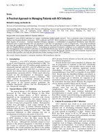
Frontispiece Photomicrographs, taken using (a)
transmitted
light and
(b) reflected light,
of
the same area of a polished thin section
of
quartzite
containing pyrite (P), sphalerite (S), muscovite (M), apatite
(A)
and abundant
quartz (Q).
The
features illustrated
in
transmitted light are: (i)
opacity-
pyrite
is
the
only
opaque phase, sphalerite
is
semi-opaque, and
the
others are transparent;
(ii) relief- very high (sphalerite, n= 2.4), moderate (apatite, n = 1.65),
moder
ate
(muscovite, n=
l.60)
, and low
(quart
z,
n=
l.SS);
(iii)
cleavage-
perfect
in
mus-
covite
(n is the refractive index
of
the
mineral).
The
feature illustrated
in
reflected light is reflectance: 54% (pyrite,
white-
true
colour slightly yellowish white), 17% (sphalerite, grey), 6% (apatite,
dark
grey),
5% (muscovite, dark grey), and 5% (quartz, dark grey) (reflectance is the
percentage of incident light reflected
by
the minera
l)
.
Note that opaque grains, grain boundaries and cleavage traces
appear
black
in
transmitted light, whereas pits (holes), grain boundaries and cleavage traces
appear black
in
reflected light.
xiv
llntroduction
to the
microscopic study
of
minerals
1.1 Introduction
Microscopes vary
in
their design, not
on
ly
in
their appearance
but
also
in
the positioning
and
operation of the various essential components.
These components are present
in
all microscopes and are described
briefly below. Although dual purpose microscopes incorporating both
transmitted- and reflected-light options are now available (Fig. 1.1 ), it
is
more convenient to describe the two techniques separately.
More
details
on the design and nature of the components can be obtained in text-
books on microscope optics.
1.2 The transmitted-light microscope
The light source
In transmitted-light studies a l
amp
is
commonly built into
the
micro-
scope base (Fig. 1.2). The typical bulb used has a tungsten filament
(A source) which gives the field
of
view a yellowish tint. A blue filter can
be inserted immediately above the light source to change the light colour
to
that
of daylight (C source).
In older microscopes the
li
ght source
is
quite separate from the
microscope and
is
usually contained
in
a hooded metal box to which can
be added a blue glass screen for daylight coloured light. A small movable
circular mirror,
one
side
of
which
is
flat and the
other
concave,
is
attached to the base of the microscope barrel.
The
mirror
is
used to
direct the light through the rock thin section on the microscope stage,
and the flat side of the mirror shou
ld
be used when a condenser
is
present.
The polariser
The assumption
is
that light consists
of
electromagnetic vibrations.
These vibrations move outwards
in
every direction from a point source
of 'white' light, such as a microscope light. A polarising
film
(the polar-
iser)
is
held within a lens system located below the stage
of
the
micro-
scope, and this
is
usually inserted into the optical path.
On
passing
through the polariser the light
is
'polarised' and now vibrates
in
a
si
ngle
1
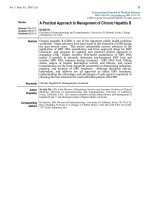
head securing
*Analyser
on/off switch
(intensity
control)
Model
MP
3502M
The
analyser
is
located on the
left-hand side
of
the
head
mounting
block on a
ll
MP3.500
microscope
models
Figure 1.1
The
Swift Student polarising microscope
(photo
courtesy
of
Swift
Ltd).
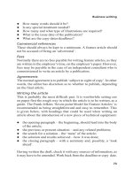
2
THE
TRANSMITTED-LIGHT
MICROSCOPE
eyepiece
turret
mount
for
Bertrand
lens
and magnifier
Bertrand
lens
~~
~~;,_
~b
-
analyser
slot for first
______
_
_,-
order
red plate
objective
+
assembly
locking piece
thin section
is
attached
to
stage by metal
-
lt
" 1
,
cl ips
"":~iD'i'i'i'1'i!!iip
-
stage
coaxial coarse
and fine
focusing lever
diaphragm
-:.:;)-
lever
1
-t=T"' o
~
polariscr
1
-~~!1
-
-t
_______
condcnser
1-
focusing
Figure 1.2 Modern transmitted
li
ght microscope.
Older
models may focus
by
moving
the
upper barrel of the microscope (not the stage as
in
the illustration),
and may use an external light source.
The
illustration
is
based on a Nikon model
POH-2
polarising microscope.
plane. This
is
called plane polarised light (PPL). In most
UK
micro-
scopes the polariser
is
oriented to give
E-W
vibrating incident light (see
also Ch. 4).
Substage diaphragms
One
or
two diaphragms may be located below the stage.
The
field
diaphragm, often omitted on simple student microscopes,
is
used to
reduce the area
of
light entering the thin section, and should be in focus
at the same position as the thin section ; it should be opened until it just
disappears from view. The aperture diaphragm
is
closed to increase
resolution; it can be seen when the
Bertrand
lens
is
inserted.
The condenser or convergent lens
A small circular lens (the condenser)
is
attached to a swivel bar, so that
it
can be inserted·into the optical train when required.
It
serves to direct a
cone
of
light on to the thin section and give optimum resolution for the
3
THE
MICROSCOPIC
STUDY
OF
MINERALS
objectives used.
The
entire lens system below the microscope stage,
including polariser, aperture diaphragm and condenser, can often be
racked upwards
or
downwards
in
order
to
optimise the quality
of
illumi-
nation. Some microscopes, however, do not possess a separate con-
vergent lens and, when a convergent lens
is
needed, the substage lens
system
is
racked upwards until it
is
just below the surface
of
the micro-
scope stage.
Stage
The microscope stage
is
flat and can be rotated. It
is
marked
in
degrees,
and a side vernier enables angles of rotation to be accurately measured.
The stage can usually be locked
in
place
at
any position.
The
rock thin
section
is
attached
to
the centre of the stage by metal spring clips.
Objectives
Objectives are magnifying lenses with the power of magnification
inscribed on each lens (e.g. xs, X30).
An
objective
of
very high power
(e.g. x 1
00) usually requires an immersion oil between the objective lens
and the thin section.
Eyepiece
The eyepiece
(or
ocular) contains crosswires which can be indepen-
dently focused by rotating its uppermost lens. Eyepieces of different
magnification are available. Monocular heads are standard on student
microscopes. Binocular heads may be used and, if correctly adjusted,
reduce eye fatigue.
The analyser
The analyser
is
similar to the polariser; it
is
also made of polarising
film
but oriented
in
a
N-S
direction, i.e. at right angles to the polariser. When
the analyser
is
inserted into the optical train, it receives light vibrating
in
an
E-W
direction from the polariser and cannot transmit this; thus the
field of view
is
dark
and the microscope
is
said to have crossed polars
(CP, XPOLS
or
XP). With the analyser out, the polariser only
is
in
position; plane polarised light
is
being used and the field of view appears
bright.
The Bertrand lens
This lens
is
used
to
examine interference figures (see Section 1.3.2).
When it
is
inserted into the upper microscope tube an interference figure
can be produced which
fills
the field of view, provided that the con-
vergent lens
is
also inserted into the optical path train.
Th
e accessory slot
Below the analyser
is
a slot into which accessory plates, e.g. quartz
wedge,
or
first
order
red, can
be
inserted.
The
slot
is
oriented so that
4
SYSTEMATIC DESCRIPTION
OF
MINERALS
accessory plates are inserted at 45° to the crosswires. In some micro-
scopes the slot may be rotatable.
Focusing
The microscope
is
focused
either
by moving the microscope stage up or
down (newer models)
or
by moving the upper microscope
tube
up or
down (older models). Both coarse and fine adjusting knobs are present.
1.3 Systematic description
of
minerals
in
thin section
using transmitted light
Descriptions of transparent minerals
are
given
in
a particular
manner
in
Chapters 2 and 3, and the terms used are explained below.
The
optical
properties of each mineral include some which are determined
in
plane
polarised light, and others which are determined with crossed polars.
For most properties a low power objective
is
used (up to x 10).
1.3.1 Properties in plane polarised light
The analyser
is
taken
out of the optical path to give a bright image (see
Frontispiece).
Colour
Minerals show a wide range of colour (by which we mean the natural
or
'body' colour
of
a mineral), from colourless minerals (such as quartz and
feldspars) to coloured minerals (brown biotite, yellow staurolite and
green hornblende). Colour
is
related to the wavelength
of
visible light,
which ranges from violet (wavelength> = 0.00039 mm or
390
nm) to
red
(>
= 760 nm). White light consists
of
all the wavelengths between
these two extremes. With colourless minerals
in
thin section (e.g.
quartz) white light passes unaffected through the mineral and
none
of
its
wavelengths
is
absorbed, whereas with
opaque
minerals (such
as
metallic ores) all wavelengths are absorbed and the mineral appears
black. With coloured minerals, selective absorption
of
wavelengths take
place and the colour seen represents a combination
of
wavelengths of
light transmitted by the mineral.
Pleochroism
Some coloured minerals change colour between two 'extremes' when
the microscope stage
is
rotated. The two extremes
in
colour are each
seen twice during a complete
(360°) rotation. Such a mineral
is
said to be
pleochroic, and ferro magnesian minerals such as the amphiboles, biotite
and staurolite
of
the common rock-forming silicates possess this
property.
5
THE
MICROSCOPIC
STUDY OF MINERALS
Pleochroism
is
due to the unequal absorption of light by the mineral
in
different orientations. For example,
in
a longitudinal section
of
biotite,
when p!ane polarised light from the polariser enters the mineral which
has its cleavages parallel to the vibration direction
of
the light, consider-
able absorption of light occurs and the biotite appears
dark
brown.
If
the
mineral section
is
then rotated through 90° so that
the
plane polarised
light from the polariser enters the mineral with its cleavages now at right
angles to the vibration direction, much less absorption of light occurs
and the biotite appears pale yellow.
Habit
This refers to the shape that a particular mineral exhibits
in
different
rock types. A mineral may
appear
euhedral, with well defined crystal
faces,
or
anhedral, where the crystal has no crystal faces present, such as
when it crystallises into gaps left between crystals formed earlier.
Other
descriptive terms include prismatic, when the crystal
is
elongate
in
one
direction, or acicular, when the crystal
is
needle like,
or
fibrous, when
the crystals resemble fibres. Flat, thin crystals are termed tabular or
platy.
Cleavage
Most minerals can
be
cleaved along certain specific crystallographic
directions which are related
to
planes
of
weakness
in
the mineral's
atomic structure. These planes
or
cleavages which are straight, parallel
and evenly spaced
in
the mineral are
denoted
by Miller's indices, which
indicate their crystallographic orientation. Some minerals such as quartz
and garnet possess no cleavages, whereas others may have one, two,
three
or
four cleavages. When a cleavage
is
poorly developed it
is
called
a parting. Partings are usually straight
and
parallel but
not
evenly
spaced.
The
number of cleavages seen depends upon the orientation of
the mineral section. Thus, for example, a prismatic mineral with a square
cross section may have two prismatic cleavages. These cleavages are
seen
to
intersect
in
a mineral section cut
at
right angles to the prism zone,
but
in
a section cut parallel to
the
prism zone the traces
of
the two
cleavages are parallel to each
other
and the mineral appears to possess
only one cleavage (e.g. pyroxenes, andalusite).
Relief
All rock thin sections are trapped between two thin layers of resin (or
cementing material) to which the glass slide and
the
cover slip are
attached.
The
refractive index
(RI)
of
the
resin
is
1.54.
The
surface relief
of a mineral
is
essentially constant (except for carbonate minerals), and
depends on the difference between the
RI
of the mineral and the
RI
of
the enclosing resin.
The
greater
the difference between the
RI
of
the
mineral and the resin, the rougher the appearance
of
the surface
of
the
mineral. This
is
because the surfaces
of
the mineral in thin section are
6
SYSTEMATIC
DESCRIPTION
OF MINERALS
made up of tiny elevations
and
depressions which reflect and refract
the light.
If
the
Rls
of
the minerai-and resin are similar the surface appears
smooth. Thus, for example, the surfaces of garnet
and
olivine which
have much higher
Rls
than
the
resin
appear
rough whereas the surface
of quartz, which has the same
RI
as
the
resin (1.54)
is
smooth and
virtually impossible
to
detect.
To
obtain a more accurate estimate
of
the
RI
of a mineral (compared
to 1.54) a mineral grain should be found
at
the edge of the thin section,
where its edge
is
against the cement.
The
diaphragm of
the
microscope
should be adjusted until the edge
of
the mineral
is
clearly defined by a
thin, bright band
of
light which
is
exactly parallel
to
the mineral bound-
ary.
The
microscope tube
is
then carefully racked upwards
(or
the
stage
lowered), and this thin band
of
light -
the
Becke line - will
appear
to
move towards the medium with
the
higher RI. For example, if
Rlmin
era
l
is
greater than Ri
ce
me
nt
the Becke line
will
appear
to move into the mineral
when the microscope tube
is
slowly racked upwards.
If
the
RI
of a
mineral
is
close to
that
of the cement then the mineral surface will
appear smooth and dispersion of the refractive index may result
in
slightly coloured Becke lines appearing
in
both media.
The
greater
the difference between a mineral's
RI
and
that
of
the
enclosing cement,
the rougher the surface of the mineral appears.
An
arbitrary scheme
used in the section of mineral descriptions
is
as follows:
RI
1.40- 1.50
1.50-1.58
1.58-1.67
1.67-1.76
> 1.76
Description
of
relief
moderate
low
moderate
high
very high
The refractive indices
of
adjacent minerals
in
the thin section may be
compared using
the
Becke line as explained.
Alteration
The most common cause
of
alteration
is
by water
or
C0
2
coming into
contact with a mineral, chemically reacting with some of its elements,
and producing a new, stable mineral phase( s). For example, water reacts
with the feldspars and produces clay minerals. In thin section this
alteration appears as an
area
of
cloudiness within the transparent feld-
spar grain.
The
alteration may be so advanced
that
the mineral
is
completely replaced by a new mineral phase. For example, crystals of
olivine may have completely altered to serpentine, but the
area
occupied
by the serpentine still has the configuration
of
the original olivine crystal.
The olivine
is
said
to
be pseudomorphed by serpentine.
7
THE
MICROSCOPIC
STUDY
OF
MINERALS
1.3.2 Properties under crossed polars
The analyser
is
inserted into
the
optical
path
to give a dark, colourful
image.
Isotropism
Minerals belonging to the cubic system
are
isotropic
and
remain
dark
under
crossed polars
whatever
their optical orientation. All
other
min-
erals
are
anisotropic and usually
appear
coloured
and
go
into extinction
(that
is, go dark)
four
times during a
complete
rotation
of
the
mineral
section. This property, however, varies with crystallographic
orienta-
tion,
and
each mineral possesses
at
least
one
orientation
which will make
the crystal
appear
to
be isotropic.
For
example,
in
tetragonal, trigonal
and hexagonal minerals, sections cut perpendicular to the
c axis are
always isotropic.
Birefringence
and
interference colour
The
colour
of
most anisotropic minerals
under
crossed polars varies,
the
same
mineral showing different colours
depending
on
its crystal-
lographic orientation. Thus
quartz
may vary from grey to white, and
olivine may show a whole
range
of
colours from grey to red
or
blue
or
green.
These
are
colours
on
Newton's
Scale, which
is
divided into
several orders:
Order
first
second
third
fourth and above
Colours
grey, white,
yellow, red
violet, blue, green,
yellow, orange, red
indigo, green, blue,
yellow, red, violet
pale pinks and green
A
Newton's
Scale
of
colours can
be
found
on
the back cover
of
this book.
These orders
represent
interference colours; they
depend
on
the
thick-
ness
of
the thin section mineral and
the
birefringence, which
is
the
difference between
the
two refractive indices
of
the
anisotropic mineral
grain.
The
thin section thickness
is
constant
(normally 30 microns) and
so interference colours
depend
on
birefringence;
the
greater
the
bi-
refringence, the higher the
order
of
the interference colours. Since the
maximum and minimum refractive indices
of
any mineral
are
oriented
along precise crystallographic directions,
the
highest interference col-
ours will be shown by a mineral section which has
both
maximum and
minimum
Rls
in the plane
of
the
section. This section will have the
maximum birefringence
(denoted
8)
of
the
mineral.
Any
differently
oriented
section will have a smaller birefringence
and
show lower col-
ours.
The
descriptive terms used in
Chapter
2
are
as follows:
8
SYSTEMATIC
DESCRIPTION
OF MINERALS
Maximum
birefringence (
ll)
0.
00-0
.018
0.018-0.036
0.036-0.055
> 0.055
Interference colour range
first
order
second
order
third
order
fourth
order
or
higher
Description
low
moderate
high
very high
Very low may be used
ifthe
birefringence
is
close to zero and
the
mineral
shows anomalous blue colours.
Interference figures
Interference
figures
are
shown by all minerals except cubic minerals.
There
are
two main types
of
interference figures (see Figs
4.19
and
21 ),
uniaxial and biaxial.
Uniaxial figures may be
produced
by suitably
orientated
sections from
tetragonal, trigonal and hexagonal minerals.
An
isotropic section
(or
near
isotropic section)
of
a mineral
is
first selected
under
crossed polars,
and
then
a high
power
objective ( x
40
or
more)
is
used with the substage
convergent lens in position
and
the
aperture
diaphragm
open.
When
the
Bertrand
lens
is
inserted into
the
optical train a black cross will
appear
in
the field
of
view.
If
the
cross
is
off
centre,
the
lens
is
rotated
so
that
the
centre
of
the cross occurs
in
the
SW (lower left hand) segment
of
the
field
of view.
The
first
order
red
accessory plate
is
then
inserted into
the
optical
train in such a way
that
the length slow direction
marked
on it points
towards the
centre
of
the
black cross,
and
the
colour in
the
NE
quadrant
of
the
cross
is
noted:
blue means that the mineral
is
positive
yellow means that the mineral
is
negative
(denoted
+ve)
(denoted
- ve)
Some accessory plates
are
length fast,
and
the
microscope may
not
allow
more than
one
position
of
insertion. In this case the length fast direction
will point towards
the
centre
of
the black cross and
the
colours
and
signs
given above would
be
reversed, with a yellow colour meaning
that
the
mineral
is
positive
and
a blue colour negative.
It
is
therefore
essential to
appreciate
whether
the
accessory plate
is
length fast
or
slow,
and
how
the fast
or
slow directions
of
the
accessory plate
relate
to
the
interfer-
ence figure
after
insertion (see Fig. 4.20).
Biaxial figures may be
produced
by suitable sections
of
orthorhombic,
monoclinic and triclinic minerals.
An
isotropic section
of
the
mineral
under
examination
is
selected and
the
microscope
mode
is
as outlined
for uniaxial figures, i.e.
X
40
objective
and
convergent lens
in
position.
Inserting
the
Bertrand
lens will usually reveal a single optic axis interfer-
ence figure which
appears
as a black
arcuate
line
(or
isogyre) crossing
9
THE
MICROSCOPIC
STUDY
OF
MINERALS
the field
of
view. Sometimes a series
of
coloured ovals will
appear,
arranged
about
a point on
the
isogyre, especially if
the
mineral section
is
very thick
or
if
the
mineral birefringence
is
very high.
The
stage
is
then
rotated
until
the
isogyre
is
in
the
45° position (relative to
the
crosswires)
and concave towards
the
NE
segment
of
the
field
of
view. In this position
the isogyre curvature can indicate the size
of
the optic axial angle
(2V)
of
a mineral. The more curved the isogyre
the
smaller
the
2V.
The
curva-
ture
will
vary from almost a 90° angle, indicating a very low
2V
(less than
10°)
to
180
o when
the
isogyre
is
straight (with a
2V
of
80° to 90°). When
the
2V
is
very small (less than 10°) both isogyres will be seen in
the
field
of
view, and
the
interference figure resembles a uniaxial cross, which
breaks up
(i
.e. the isogyres move apart) on rotation.
The
first
order
red
accessory plate (length slow)
is
inserted
and
the
colour
noted
on the
concave side
of
the
isogyre:
blue means that
the
mineral
is
positive (
+ve)
yellow means
that
the
mineral
is
negative (
-ve)
If
the accessory plate
is
length fast (as mentioned
in
the preceding
section) the colours above
will
be
reversed,
that
is
a yellow colour will be
positive and blue negative (see Fig.
4.20).
Extinction angle
Anisotropic minerals go into extinction four times during a complete
360° rotation
of
a mineral section.
If
the
analyser
is
removed from the
optical train while
the
mineral grain
is
in extinction,
the
orientation
of
some physical property
of
the mineral, such
as
a cleavage
or
trace
of
a
crystal face edge, can be related to the microscope crosswires.
All uniaxial minerals possess straight
or
parallel extinction since a
prism face
or
edge,
or
a prismatic cleavage,
or
a basal cleavage,
is
parallel
to
one
of
the
crosswires when
the
mineral
is
in extinction.
Biaxial minerals possess
either
straight
or
oblique extinction.
Orthorhombic
minerals (olivine, sillimanite, andalusite, orthopyrox-
enes) show straight extinction against
either
a prismatic cleavage
or
a
prism face edge. All
other
biaxial minerals possess oblique extinction,
although in some minerals
the
angular displacement may be extremely
small: for example, an elongate section
of
biotite showing a basal cleav-
age goes into extinction when these cleavages are almost parallel
to
one
of
the microscope crosswires.
The
angle through which the mineral has
then to be
rotated
to bring
the
cleavages parallel to the crosswire
will
vary from nearly
oo
to
9°
depending on
the
biotite composition,
and
this
angle is called
the
extinction angle.
The
maximum extinction angle
of
many biaxial minerals
is
an import-
ant optical property and has
to
be precisely determined. This
is
done
as
follows. A mineral grain
is
rotated
into extinction,
and
the
angular
position
of
the microscope stage
is
noted.
The
polars are uncrossed (by
10
SYSTEMATIC
DESCRIPTION
OF MINERALS
removing
the
upper
analyser from
the
optical train)
and
the mineral
grain
rotated
until a cleavage trace
or
crystal trace edge
or
twin plane
is
parallel to
the
crosswires in
the
field
of
view.
The
position
of
the
microscope stage is again
noted
and
the
difference between this reading
and
the former
one
gives
the
extinction angle
of
the
mineral grain.
Several grains
are
tested since
the
crystallographic orientation may vary
and
the
maximum
extinction angle
obtained
is
noted
for
that
mineral.
The
results
of
measurements from several grains should
not
be
aver-
aged.
Extinction angles are usually given in mineral descriptions as
the
angle between
the
slow (y)
or
fast (a) ray
and
the
cleavage
or
face
edge (written as
y
or
a·cl),
and
this technique
is
explained in detail in
Chapter
4.
In many biaxial minerals
the
maximum extinction angle
is
obtained
from a mineral grain which shows maximum birefringence such as, for
example,
the
clinopyroxenes diopside, augite and aegirine,
and
the
monoclinic amphiboles tremolite and
the
common hornblendes. How-
ever, in some minerals
the
maximum extinction angle
is
not
found in a
section showing maximum birefringence. This
is
so for the clinopyrox-
ene pigeonite,
the
monoclinic amphiboles crossite, katophorite and
arfvedsonite,
and
a few
other
· minerals
of
which kyanite
is
the
most
important (see also Ch. 4, Section
4.10).
Throughout
the mineral descriptions given in
Chapter
2, large varia-
tions in the maximum extinction angle
are
shown for particular minerals.
For
example the maximum extinction angles for the amphiboles
tremolite-actinolite are given as between
18°
and
11° (y·cleavage).
Tremolite, the Mg-rich
member,
has a maximum extinction angle be-
tween 21° and 17°, whereas ferroactinolite has a maximum extinction
angle from
17°
to
11°. This variation in
the
extinction angle
is
caused
mainly by variations in the Mg: Fe ratio. Variation in extinction angles
are common in many minerals
or
mineral pairs which show similar
chemical changes.
Twinning
This property
is
present
when areas with differing extinction
orienta-
tions within the same mineral grain have planar contacts.
Often
only a
single twin plane
is
seen, but in some minerals (particularly plagioclase
feldspars) multiple
or
lamellar twinning occurs with parallel twin planes.
Zoning
Compositional variation (zoning) within a single mineral may
be
ex-
pressed in terms
of
changes
of
'natural'
colour from
one
zone to an
adjoining one;
or
by changes in birefringence;
or
by changes in extinc-
tion orientation. These changes may
be
abrupt
or
gradational, and
commonly occur as a sequence from
the
core
of
a mineral grain (the
early-formed part) to its edge (the last-formed part).
11
THE
MICROSCOPIC
STUDY OF MINERALS
Zoning
is
generally a growth phenomenon and
is
therefore related to
the crystal shape.
Dispersion
Refractive index increases as the wavelength oflight decreases. Thus the
refractive index
of
a mineral for red light
is
less than for blue light (since
the wavelength
of
red light
is
greater than the wavelength of blue light).
White light entering a mineral section
is
split into the colours of the
spectrum, with blue nearest to the normal (i.e. the straight through path)
and red the furthest away. This breaking up of the white light
is
called
dispersion. In most minerals
the
amount
of
dispersion
is
very small and
will
not affect the mineral's optical properties. However, the Na-rich
clinopyroxenes, the Na-rich amphiboles, sphene, chloritoid, zircon and
?rookite
possess very strong dispersion. With many of these minerals,
mterference figures may be difficult to obtain and the use of accessory
plates (to determine mineral sign etc.) may not be possible.
Each mineral possesses a
few
diagnostic properties,
and
in
the descrip-
tions
in
Chapter 2 these have been marked with an asterisk. Sometimes
a final paragraph discusses differences between the mineral being
described and
other
minerals that have similar optical properties.
1.4 The reflected-light microscope
The light source
A high intensity source (Fig. 1.3)
is
required for reflected-light studies,
mainly because
of
the low brightness
of
crossed polar images.
Tungsten-halogen quartz lamps are used, similar
to
those in transpa-
rency projectors,
and
the tungsten light
(A
source) gives the field a
yellowish tint. Many microscopists prefer
to
use a blue correction filter
to change the light colour to that of daylight (C source). A
monochro-
matic light source (coloured light corresponding to a very limited range
of the visible spectrum)
is
rarely used in qualitative microscopy, but
monochromatic filters for
the
four standard wavelengths ( 4 70 nm,
546 nm, 589 nm and 650 nm) could be useful
in
comparing the
brightness of coexisting minerals, especially now
that
quantitative
measurements
of
brightness are readily available.
The polariser
Polarised light
is
usually obtained
by
using a polarising film,
and
this
should be protected from the
heat
of
the lamp
by
a glass heat filter.
The
polariser should always be inserted
in
the optical train.
It
is
best fixed
in
orientation to give
E-W
vibrating incident light. However, it
is
useful to
be able to rotate
the
polariser
on
occasion
in
order
to correct its orien-
tation
or
as an alternative to rotating the analyser.
12
Smith
ill
uminator
revolving
ob
jecti
ve
changer
THE REFLECTED-LIGHT
MICROSCOPE
l~>, 4-
heat absorbing filter
aperture
diaphragm
fie
ld
.,__
______
diaphragm
l.~
~:::l b;==-
focusing
control
stage
centring
<
1
1 "'""
screws
coarse
focus
fine focus
Figure 1.3 The Vickers M73 reflected light microscope. Note that it
is
the polariser th at rotates
in
!his microscope.
The incident illuminator
The incident illuminator sits above the objective and its purpose
is
to
reflect light down through the objective
on
to
the polished specimen. As
the reflected light travels back up through
the
objective
to
the eyepiece it
must
be
possible for this light
to
pass through the incident illuminator.
There are three types of reflector used
in
incident illuminators
(Fig. 1.4):
13
Figure 1.4
Incident
illuminators.
THE
MICROSCOPIC
STUDY
OF
MINERALS
(a) The cover glass
or
coated thin glass plate (Fig. 1.4a). This
is
a
simple device, but
is
relatively inefficient because of light loss both
before and after reflection from the specimen. However, its main
disadvantage when
at
45° inclination
is
the lack of uniform extinc-
tion of an isotropic field . This
is
due to rotation
of
the vibration
direction
of
polarised reflected light which passes asymmetrically
through the cover glass on returning towards the eyepiece. This
disadvantage
is
overcome by decreasing the angle to about 23°
as
on Swift microscopes.
(b) The mirror plus glass plate
or
Smith illuminator (Fig. 1.4b ). This
is
slightly less efficient than the cover glass but, because
of
the low
angle (approaching perpendicular)
of
incidence
of
the returning
reflected light on the thin glass plate, extinction
is
uniform and
polarisation colours are quite bright. This illuminator
is
used on
Vickers microscopes.
(c) The prism
or
total reflector (Fig. 1.4c). This
is
more efficient than
the glass plate type
of
reflector but it
is
expensive.
It
would be 100
per
cent efficient, but half
of
the light
flux
is
lost because only half
of the
aperture
of
the objective
is
used. A disadvantage
is
the lack
of
uniform extinction obtained. A special type
of
prism
is
the
triple
prism or Berek prism, with which very uniform extinction
is
obtained because
of
the nature
of
the prism (Hallimond 1970,
p. 103). Prism reflectors are usually only available on research
microscopes and are normally interchangeable with glass plate
reflectors.
One
of
the disadvantages
of
the prisms
is
that the
incident light
is
slightly oblique, and this can cause a shadow effect
on surfaces with high relief. Colouring
of
the shadow may also
occur.
to
eyepiece
sample
14
(a) Cover glass
illuminator
(b)
Smith
illuminator
(c) Prism illuminator
THE REFLECTED-LIGHT
MICROSCOPE
Objectives
Objectives are magnifiers and
are
therefore described
in
terms
of
their
magnification power, e.g. x
5.
They are also described using numerical
aperture (Fig. 1.5), the general rule being the higher the numerical
aperture the larger
the
possible magnification.
It
is
useful to remember
that, for objectives described as being
of
the
same magnification, a
higher numerical aperture leads to finer resolved detail, a smaller depth
of focus and a brighter image. Objectives are designed for use with
either
air (dry)
or
immersion oil between the objective lens and the sample.
The use of immersion oil between the objective and sample leads to an
increase
in
the numerical aperture value (Fig. 1.5). Immersion objec-
tives are usually engraved as such.
Low power objectives can usually be used for either transmitted
or
reflected light, but
at
high magnifications(> x 10) good images can only
be obtained with the appropriate type
of
objective. Reflected-light
objectives are also known as metallurgical objectives. Achromatic
objectives are corrected for chromatic aberration, which causes colour
fringes
in
the image due to dispersion effects. Planochromats
are
also
corrected for spherical aberration, which causes a loss
in
focus away
from the centre of a lens; apochromats are similarly corrected
but
suffer
from chromatic difference
of
magnification, which must be removed
by
use
of
compensating eyepieces.
object
ive
IV
optic axis
of
1
micr
oscope
1
x20
immer
sion
NA
=
0.45
o
il
, n = 1
.52
surface
in
focus
resolution,
d =
0.61-lm
(A.
=
550
nm)
Figure 1.5 Numerical
ape
rture
and resolution. N.A. = n
si
n
p.
,
where
N.A. = numerical
ape
rture
, n = refractive index
of
immer
sion medium,
and
p.
= half
the
angle
of
the
light
cone
entering
the
objective lens
(for
air, n = 1.0).
d =
0.5
A.
/N.A. where d =
the
resolution
(the
distance
between
two points
that
can
be
resolved)
and
A.
is
in
microns
(1
micron = 1000 nm).
The
working distance
(w
in
the
diagram)
depends
on
the
construction of
the
lens; for
the
same
magnification, oil immersion lenses usually h
ave
a
shorter
distance than dry
objectives.
15
THE
MICROSCOPIC
STUDY OF MINERALS
Analyser
The analyser may be moved
in
and out
of
the
optical train and rotated
through small angles during observation
of
the specimen.
The
reason for
rotation
of
the analyser
is
to enhance the effects of anisotropy.
It
is
taken
out to give plane polarised light (PPL), the field appearing bright, and
put
in
to give crossed polars (XPOLS), the field appearing dark. Like
the
polariser, it
is
usually made of polarising film.
On
some microscopes the
analyser
is
fixed in orientation and the polariser
is
designed to rotate.
The effect
is
the same
in
both cases, but
it
is
easier to explain the
behaviour
of
light assuming a rotating analyser (Section 5.3).
The Bertrand lens
This
is
usually little used in reflected-light microscopy, especially
by
beginners. The polarisation figures obtained are similar,
but
differ
in
origin and use, to the interference figures
of
transmitted-light
microscopy.
Isotropic minerals give a black cross which
is
unaffected by rotation of
the stage but splits into two isogyres on rotation of
the
analyser. Lower
symmetry minerals give a black cross
in
the extinction position, but
the cross separates into isogyres on rotation
of
either
the
stage
or
the analyser. Colour fringes on the isogyres relate to dispersion
of
the
rotation properties.
Light control
Reflected-light microscopes are usually designed to give Kohler-type
critical illumination (Galopin
& Henry 1972, p. 58). As far as
the
user
is
concerned, this means that the aperture diaphragm and
the
lamp
filament can be seen using conoscopic light (Bertrand lens in) and the
field diaphragm can be seen using orthoscopic light (Bertrand lens out).
A lamp rheostat
is
usually available on a reflected-light microscope to
enable the light intensity to be varied. A very intense light source
is
necessary for satisfactory observation using crossed polars. However,
for PPL observations the rheostat
is
best left
at
the manufacturer's
recommended value, which should result
in
a colour temperature
of
the
A source. The problem with using a decreased lamp intensity to
decrease image brightness
is
that this changes the overall colour of the
image. Ideally, neutral density filters should be used to decrease bright-
ness if the observer finds it uncomfortable. In this respect, binocular
microscopes prove less wearisome on
the
eyes than monocular
microscopes.
Opening of the aperture diaphragm decreases resolution, decreases
the depth
of
focus and increases brightness. It should ideally be kept
only partially open for PPL observation
but
opened fully when using
crossed polars.
If
the aperture diaphragm can be adjusted, it
is
viewed
us
ing
the Bertrand lens
or
by removing the ocular (eyepiece). Figure 1.6
16
Figure 1.6
Centring of the
aperture
diaphragm.
THE APPEARANCE
OF
POLISHED SECTIONS
crosswires
:€8
> > .
ap
erture · · ·
diaphragm · ·
edge of
prism
Correctly centred
aperture
diaphragm
for a plate glass reflector
im
age with Be
rtr
and lens
in
serted
and aperture
di
aphragm
cl
osed
Correctly
centred
aperture
diaphragm
for a prism reflector
im
age with Bertrand lens
in
serted and
aperture
di
a
phr
agm
cl
osed
shows the aperture diaphragm correctly centred for glass plate and
prism reflectors.
The illuminato; field diaphragm
is
used simply to control scattered
light.
It
can usually be focused and should be
in
focus
at
the same
position as the specimen image. The field diaphragm should be opened
until it just disappears from the field
of
view.
1.5 The appearance
of
polished sections under the
reflected-light microscope
On first seeing a polished section
of
a rock
or
ore sample the observer
often finds that interpretation of the image
is
rather difficult.
One
reason
for this
is
that most students use transmitted light for several years
before being introduced to reflected light, and they are conditioned into
interpreting bright areas as being transparent and dark areas as being
opaque; for polished sections the opposite
is
the case! It
is
best to begin
·examination of a polished section such as
that
illustrated
in
Figure 1.7
by
using low power magnification and plane polarised light, when most
of
the following features can be observed:
(a) Transparent phases
appear
dark grey. This
is
because they reflect
only a small proportion of
the
incident light, typically 3 to 15 %.
Occasionally bright patches are seen within areas of transparent
minerals, and are due to reflection from surfaces
under
the
polished surface.
(b) Absorbing phases (opaques
or
ore minerals) appear grey to bright
white as they reflect much more of the incident light, typically 15 to
95
%. Some absorbing minerals
appear
coloured, but usually
colour tints are very slight.
17
THE
MICROSCOPIC
STUDY
OF
MINERALS
I
mm
Figure 1.7 Diagrammatic representation of a polished section
of
a
samp
le
of
lead ore. Transparent phases, e.g. fluorite (A), barite (B)
and
the
mounting resin
(D)
appear
dark grey. Their brightness depends
on
their refractive index.
The
fluorite
is
almost black. Absorbing phases (opaque) , e.g. galena (C),
appea
r
white. Holes, pits
and
cracks
appear
black. Note the black triangular cleavage pits
in
the galena and
the
abundant
pits
in
the barite which results, not from
poor
polishing, but from the abundant fluid inclusions. Scratches
appear
as long
straight
or
curving lines.
They
are quite
abundant
in
the galena which
is
soft and
scratches
easily.
(c) Holes, pits, cracks and specks
of
dust appear black. Reflection
from crystal faces
in
holes may give peculiar effects such as very
bright patches of light.
(d) Scratches on the polished surface
of
minerals appear as long
straight
or
curving lines, often terminating
at
grain boundaries or
pits. Severe fine scratching can cause a change
in
the appearance of
minerals. Scratches on native metals, for example, tend to scatter
light and cause colour effects.
(e)
Patches of moisture
or
oil tend to cause circular dark
or
iridescent
patches and indicate a need for cleaning
of
the polished surface.
(f) Tarnishing
of
minerals
is
indicated by an increase
in
colour inten-
sity, which tends to be rather variable. Sulphides, for example
bornite, tend to tarnish rapidly. Removal of tarnishing usually
requires a few minutes buffing
or
repolishing.
(g)
Polishing relief, due to
the
differing hardnesses of adjacent miner-
a
ls
, causes dark
or
light lines along grain contacts. Small soft bright
grains may
appear
to glow, and holes may have indistinct dark
margins because of polishing relief.
18
SYSTEMATIC
DESCRIPTION
OF MINERALS
1.6 Systematic description
of
minerals in polished section
using reflected light
Most of the
ore
minerals described in Chapter 3 have a heading
'polished section'.
The
properties presented under this heading are in a
particular sequence, and
the
terms used are explained
bri.efly
b~low.
~
ot
all properties are shown by each mineral, so only properties whtch mtght
be observed are given
in
Chapter 3.
1.6.1 Properties observed using plane polarised light
(PPL)
The analyser
is
taken
out
of the optical path to give a bright image (see
Frontispiece).
Colour
Most minerals are only slightly coloured when observed using PPL, and
the colour sensation depends on factors such as the type of microscope,
the light source and the sensitivity of an individ.ual's eyes.
Colou~
is
therefore usually described simply
as
being a vanety
of
grey
or
whtte,
e.g. bluish grey rutile, pinkish white cobaltite.
Pleochroism
If
the colour of a mineral varies from grain to grain and individual grains
change in colour on rotation
of
the
stage, then the mineral
is
P.leochroic.
The colours for different crystallographic orientations are gtven when
available. Covellite, for example, shows two extreme colours, blue and
bluish light grey. Pleochroism can often be observed only by careful
examination of groups of grains
in
different crystallographic orientation.
Alternatively the pleochroic mineral may be examined adjacent to a
non-pleochroic mineral, e.g. ilmenite against magnetite.
l?
efl ctance
This is the percentage of light reflected from the polished surface of the
min
rat, and where possible values are given for each crystallographi.c
orientation.
The
eye
is
not good
at
estimating absolute reflectance
butts
u good comparator.
The
reflectance values of the minerals should there-
fore be used for
the
purpose of comparing minerals. Reflectance can be
reluted to a grey scale of brightness in
the
following way,
but
although
followed
in
this book it
is
not a rigid scale. A mineral
of
reflectance
-
15
% (e.g. phalerite) may
appear
to
be
light grey
or
white compared
with a l
ow
reflectance mineral (such as quartz) or
dark
grey compared
with a bright mineral (such as pyrite):
19
THE
MICROSCOPIC
STUDY
OF
MINERALS
R(%)
Grey scale
0-10
dark grey
10-20 grey
20-40 light grey
40-60 white
60-100 bright
~hite
Bireflectan
ce
This
is
a quantitative value, and for an anisotropic grain
is
a measure of
the difference between the maximum and minimum reflectance values.
However, bireflectance
is
usually assessed qualitatively, e.g.
Weak bireflectance: observed with difficulty,
t!.R.
<
5%
(e.g. hematite)
Distinct bireflectance: easily observed,
t!.R.
>
5%
(e.g. stibnite)
Pleochroism and bireflectance are closely related properties; the term
pleochroism
is
used to describe change
in
tint
or
colour intensity,
whereas bireflectance
is
used for a change
in
brightness.
1.6.2 Properties observed using crossed polars
The analyser
is
inserted into the optical path to give a dark image.
Anisotropy
This property varies markedly with crystallographic orientation
of
a
section of a non-cubic mineral. Anisotropy
is
assessed as follows:
(a) Isotropic mineral: all grains remain dark on rotation
of
the
stage,
e.g. magnetite.
(b) Weakly anisotropic mineral: slight change on rotation, only seen
on careful examination using slightly uncrossed polars, e.g.
ilmenite.
(c) Strongly anisotropic mineral: pronounced change
in
brightness
and possible colour seen on rotating the stage when using exactly
crossed polars, e.g. hematite.
Remember that some cubic minerals (e.g. pyrite) can
appear
to be
anisotropic, and weakly anisotropic minerals (e.g. chalcopyrite) may
appear
to be isotropic. Anisotropy and bireflectance are related proper-
ties; an anistropic grain
is
necessarily bireflecting, but the bireflectance
in
PPL
is
always much more difficult to detect than the anisotropy
in
crossed polars.
20
SYSTE
MATIC
DESCRIPTION OF MINERALS
Internal reflections
Light may pass through the polished surface
of
a mineral and be
reflected back from below. Internal reflections are therefore shown
by
a
ll
transparent minerals. When one
is
looking for internal reflections,
particular care should be paid to minerals of low to moderate reflectance
(semi-opaque minerals), for which internal reflections might only be
detected with difficulty and only near grain boundaries
or
fractures.
Cinnabar, unlike hematite which
is
otherwise similar, shows spectacular
red internal reflections.
1.
6.3 The external nature
of
grains
Minerals have their grain shapes determined
by
complex variables act-
ing during deposition and crystallisation and subsequent recrystallisa-
tion, replacement
or
alteration. Idiomorphic (a term used
by
reflected-
light microscopists for well shaped
or
euhedral) grains are unusual, but
some minerals
in
a polished section will be found to have a greater
tendency towards a regular grain shape than others.
In
the
ore
mineral
descriptions
in
Chapter 3,
the
information given under the heading
'crystals'
is
intended to be an aid to recognising minerals on the basis of
grain shape. Textural relationships are sometimes also given.
1.6.4 Internal properties
of
grains
Twinning
This
is
best observed using crossed polars, and
is
recognised when areas
with differing extinction orientations have planar contacts within a
single grain. Cassiterite
is
commonly twinned.
Cleavage
This
is
more difficult to observe
in
reflected light than transmitted light,
and
is
usually indicated
by
discontinuous alignments of regularly shaped
or
rounded pits. Galena
is
characterised by its triangular cleavage pits.
Scratches sometimes resemble cleavage traces. Further information on
twinning and cleavage
is
given under the heading
of
'c
rystals'
in
the
descriptions
in
Chapter
3.
Zoning
Compositional zoning of chemically complex minerals such as tetrahed-
rite
is
probably very common
but
rarely gives observable effects such as
colour banding. Zoning of micro-inclusions
is
more common.
Inclusions
The identity and nature
of
inclusions commonly observed
in
the mineral
i given, as this knowledge can be an aid to identification. Pyrrhotite, for
example, often contains lamellar inclusions
of
pentlandite.
21
THE
MICROSCOPIC
STUDY OF MINERALS
1.6.5 Vickers hardness number (VHN)
This
is
a quantitative value
of
hardness which
is
useful to know when
comparing the polishing properties
of
minerals (see Section 1.9).
1.
6.
6 Distinguishing features
These are given for the mineral compared with other minerals
of
similar
appearance. The terms harder
or
softer refer to comparative polishing
hardness (see Section 1.8).
1. 7 Observations using oil immersion
in
reflected-light
studies
Preliminary observations on polished sections are always made simply
with air
(RI
= 1.0) between
the
polished surface and
the
microscope
objective, and for most purposes this suffices. However, an increase in
useful magnification and resolution can be achieved by using immersion
objectives which require oil (use microscope manufacturer's recom-
mended oil, e.g. Cargille oil type
A)
between the objective lens and the
section surface. A marked decrease
in
glare
is
also obtained with the use
of immersion objectives. A further reason for using oil immersion
is
that
the ensuing change
in
appearance
of
a mineral may aid its identification.
Ramdohr (1969) states:
'It
has to be emphasised over and over again
that whoever shuns the use
of
oil immersion misses an important diag-
nostic tool and
will
never see hundreds
of
details described in this book.'
Table 1.1 The relationship between the reflectances of minerals
in
air (Ra;,) and
oil
immersion (Ron) and their optical constants, refractive index (n) and absorp-
tion coefficient (k). Hematite
is
the
only non-cubic mineral represented, and two
sets
of
values corresponding to
the
ordinary (o) and extraordinary (e) rays are
given.
N
is
the refractive index
of
the immersion medium.
n
k
R
a;
c(
%)
Roll( %)
(N = 1.0)
(N = 1.52)
Transparent minerals
fluorite CaF,
1.434
0.0
3.2
0.08
sphalerite ZnS
2.38
0.0
16.7
4.9
Weakly absorbing minerals
hematite
Fe,O
,
(o)
3.15
0.42
27.6
12.9
(e)
2
.8
7
0.32
23.9
9.9
Absorbing (opaque) minerals
galena PbS
4.3
1.7
44.5
28.9
silver Ag
0.18 3.65
95.1
93.2
22
POLISHING
HARDNESS
Oil immersion nearly always results in a decrease
in
reflectance
(Table 1.1), the reason being evident from examination of the Fresnel
equation (Section 5.1.1), which relates
the
reflectance
of
a mineral to its
optical properties
and the refractive index (N) of the immersion
medium. Because it
is
then-Nand
then+
N values in
the
equation that
are affected, the decrease
in
reflectance
that
results from the increase
in
N
is
greater for minerals with a lower absorption coefficient (see
Table
1.1).
The colour of a mineral may remain similar
or
change markedly from
air to oil immersion. The classic example of this
is
covellite, which
changes from blue in air to red
in
oil, whereas the very similar blau-
bleibender covellite remains blue in both air and oil.
Other
properties,
such as bireflectance and anisotropy, may be enhanced
or
diminished
by
use
of
oil immersion.
To use oil immersion, lower the microscope stage so that the immer-
sion objective
is
well above the area
of
interest on
the
well levelled
polished section. Place a droplet
of
recommended oil on the section
surface and preferably also on
the
objective lens. Slowly raise
the
stage
using the coarse focus control, viewing from
the
side, until
the
two
droplets
of
oil just coalesce. Continue to raise the stage very slowly using
the fine focus, looking down the eyepiece until
the
image comes into
focus. Small bubbles may drift across the field but they should
not
cause
a
ny
inconvenience. Larger bubbles, which tend to be caused by moving
the sample too quickly, may only be satisfactorily removed by complete
cleaning.
To clean the objective, lower
the
stage and immediately wipe the end
of
the
objective with a soft tissue. Alcohol may be used with a tissue, but
not a solvent such as acetone, which may result
in
loosening
of
the
objective lens. The polished section can be carefully lifted from the stage
and cleaned
in
the same way.
Most aspects
of
qualitative
ore
microscopy can be undertaken without
resource to oil immersion, and oil immersion examination of sections
which are subsequently to be carbon coated for electron beam micro-
analysis should
be
avoided.
The
technique
is
most profitably employed
in
the study
of
small grains
of
low reflectance materials such as graphite
or organic compounds, where the benefits are a marked increase in
resolution and image quality
at
high magnification.
1.8 Polishing hardness
During
the
polishing process, polished sections inevitably develop some
relief (or topography) owing to the differing hardness of the component
minerals. Soft minerals tend to be removed more easily
than
hard
minerals. Also the surfaces of hard grains tend to become convex,
whereas the surfaces
of
soft grains
tend
to become concave.
One
of the
23
THE
MICROSCOPIC
STUDY
OF
MINERALS
challenges of the polishing technique has been to totally avo
id
relief
during polishing. This
is
because
of
the detrimental effect of polishing
relief
on
the appearance of the polished section, as well as the necessity
for optically fiat polished surfaces for reflectance measurements. As
some polishing relief
is
advantageous
in
qualitative mineral
identification it
is
often beneficial to enhance the polishing relief by
buffing the specimen for a few minutes using a mild abrasive such as
gamma alumina on a soft nap.
Polishing relief results
in
a phenomenon known as the Kalb light line,
which
is
similar
in
appearance to a Becke line. A sharp grain contact
between. a hard mineral such as pyrite
and
a soft mineral such as
chalcopyrite should
appear
as a thin dark line when the specimen
is
exactly
in
focus.
On
defocusing slightly by increasing the
<;listance
be-
tween the specimen and objective, a fine line
of
bright light should
appear along the grain contact
in
the softer mineral.
The
origin
of
this
light line
shourct easily be understood on examination
of
Figure 1.8.
Ideally the light line should move away from the grain boundary as the
specimen
is
further defocused.
On
defocusing
in
the opposite sense the
light line appears in the
harder
mineral, and defocusing
in
this sense
is
often necessary as the white line
is
difficult to see
in
a bright white soft
mineral.
The
light line
is
best seen using low power magnification
and
an
almost closed
aperture
diaphragm.
The
Kalb light line
is
used to determine
the
relative polishing hardness
of
minerals
in
contact
in
the same polished section. This sequence can be
used to confirm optical identification
of
the mineral set,
or
as an aid to
the identification
of
individual minerals, by comparison with published
lists of relative polishing hardness (e.g.
Uytenbogaardt
& Burke 1971 ).
-
F2
Figure 1.8 Relative polishing
hardnes
s.
The
position of focus
is
first
at
F,.
If
the
specimen
is
now lowered away from
the
objective,
the
level
that
is
in
focus will
move to
F,, so
that
a light line
(the
' Kalb light line
')
appears
to
move into
the
softer substance.
24
MICROHARDNESS
(VHN)
Relative polishing hardness can
be
of
value
in
the study of micro-
inclusions
in
an identified host phase; comparison
of
the hardness of an
inclusion and its surround may
be
used
to
estimate the hardness of the
inclusion
or
eliminate some
of
several possibilities resulting from
identification
attempted
using optical properties. Similarly, if optical
properties cannot
be
used to identify a mineral with certainty, compari-
son
of
polishing hardness with an identified coexisting mineral may help.
For example, pyrrhotite
is
easily identified and may
be
associated with
pyrite
or
pentlandite, which are similar
in
appearance; however, pyrite
is
harder than pyrrhotite whereas pentlandite
is
softer.
1.9 Microhardness (VHN)
The
determination
of
relative polishing hardne
ss
(Section 1.8)
is
used in
the mineral identification chart (Appendix
C). Hardness can however
be measured quantita_tively using microindentation techniques. The
frequently used hardness value, the Vickers hardness number
(VHN),
is
given for each mineral listed in Appendix
C.
Microindentation hardness
is
the most accurate method
of
hardness
determination and,
in
the case
of
the
Vickers technique, involves
pressing a small square based pyramid
of
diamond into the polished
urface.
The
diamond
may
be
mounted
in
the centre
of
a special objec-
tive, with bellows enabling the load to be applied pneumatically
(Fig. 1.9).
The
Commission
on
Ore
Microscopy
(COM)
recommend
five
preselected
l
oads
indenter
object
ive
I
diamo
nd
pneumatic
transmitt
er
cylinder
IO
cm
transmitter
level
l
•
'
l~:ure
1.9 Vickers microindentation hardness tester.
25
Figure 1.10
Indent
a
ti
on
shape
s.
THE
MICROSCOPIC
STUDY
OF
MINERALS
that a load of 100 grams should be applied for 15 seconds.
The
size
of
the resulting square shaped impression depends on the hardness
of
the
mineral:
VHN
= 1854 X load
dz kglmm
2
where the load
is
in
kilograms and d
is
the average length
of
the
di
agonals
of
the impression in microns.
Hardness
is
expressed
in
units
of
pressure, that is, force
per
unit area.
Thus the microindentation hardness
of
pyrite
is
written:
pyrite,
VHN
100
=
1027-1240
kglmm
2
The subscript 100 may be omitted as this
is
the standard load.
As
VHN
values are always given
in
kglmm
2
this
is
also often omitted.
The determination of hardness
is
a relatively imprecise technique, so
an average
of
several indentations should be used. Tables
of
VHN
usually give a range
in
value for a mineral, taking into account variations
du~
to
compositi~n.al
variations, anistropy of hardness and uncertainty.
Br~ttleness,
plastiCity and elasticity control the shape
of
the
inden-
tatiOns, and as the shape can be useful in identification the
COM
r~commends
that indentation shape (using the abbreviations given
in
Fig. 1.10) be given with
VHN
values.
There
is
a reasonable correlation between VHN and Moh's scratch
hardness as shown
in
Table 1.2.
1.10 Points on the use
of
the microscope (transmitted and
reflected light)
Always focus using low power first.
It
is
safer to start with the specimen
surface close to the objective and
lower
the
stage
or
raise the tube to
achieve the position of focus.
26
p
(perfect)
sf
(s
li
ghtly
fr
ac
tur
ed)
cc
(concav
e)
cv
(convex)
(fra
ctur
ed)
POINTS
ON
USE
OF
MICROSCOPE
Table 1.2 Relation between
VHN
and Moh's hardness.
Moh's
hardne
ss (H)
- VHN
1
ta
lc
10
2 gypsum
40
3
calcite
100
4 fluorite
2
00
5
apatite
500
6
orthoclase
750
7
quart
z
1300
8
topa
z
17
00
9
corundum
2400
[10
diamond]
Thin sections must always be placed on the stage with the cover slip on
top
of
the
section, otherwise high power objectives may not focus
properly.
Polished samples must be level. Blocks may be mounted on a small
sphere
of
plasticine on a glass plate and pressed gently with a levelling
device. Carefully machined polished blocks with parallel faces can usu-
a
ll
y be placed directly on the stage. A level sample should
appear
uniformly illuminated. A more exact test
is
to focus on the samples, then
cl
ose
the
aperture diaphragm (seen using the Bertrand lens) and rotate
the stage.
The
small spot
of
light seen as
the
image should not wobble
if
the sample
is
level.
Good polished surfaces require careful preparation and
are
easily
ruined. Never touch
the
polished surface
or
wipe it with anything
other
than a clean soft tissue, preferably moistened with alcohol
or
a pro-
pri
et
a
ry
cleaning fluid. Even a dry tissue can scratch some soft minerals.
Specimens not
in
use should be kept covered
or
face down on a tissue.
The analyser
is
usually fixed
in
orientation on transmitted-light
mi
croscopes
but
the polariser may be free to rotate.
There
is
no need to
rotate the polariser during normal use
of
the
microscope and it should be
positioned to give east- west vibrating polarised light. To check that the
polars are exactly crossed examine an isotropic substance such as glass
and adjust the polaris
er
to give maximum darkness (complete
ex
tinction).
The alignment
of
polariser and anlyser for reflected light can be set
approximately fairly easily. Begin
by
obtaining a level section of a bright
i o
tr
opic mineral such as pyrite.
Rotate
the
analyser and polariser to
their zero positions, which should be marked on the microscope. Check
th
at the polars are crossed, i.e. the grain
is
dark. Rotate the analyser
s
li
ghtly to give as dark a field as possible. View the polarisation figure
(s
ee
Section 1.4 ). Adjust the analyser (and/or polariser) until a perfectly
centred
bl
ack cross
is
obtained. Examine an optically homogeneous area
of a uniaxial mineral such
as
ilmenite, niccolite
or
hematite. Using
27
Figure 1.11
Sections.
THE
MICROSCOPIC
STUDY
OF
MINERALS
crossed polars it should have four extinction positions at 90°, and
the
polarisation colours seen
in
each
quadrant
should be identical.
Adjust
the polariser and analyser until the best results are obtained (see
Hallimond
1970, p. 101).
Ensure
that
the stage
is
well centred using the high power objective
before studying optical figures.
1.11 Thin- and polished-section preparation
Thin sections are prepared by cementing thin slices of rock to glass and
carefully grinding using carborundum grit to produce a paper thin layer
of
rock.
The
standard thickness
of
30 microns
is
estimated using the
interference colours of known minerals
in
the section. A cover slip
is
finally cemented on top of the layer of rock (Fig. 1.11).
The
three common types
of
polished section are shown
in
Figure 1.11.
Preparation
of
a polished surface of a rock
or
ore
sample
is
a
rather
involved process which involves
five
stages:
(1) Cutting the sample with a diamond saw.
(2) Mounting the sample on glass
or
in
a cold-setting resin.
Thin section
Polished block
polished
surface
~
~
glass sl
td
c
rock slice
30
IJ.m
thick
Polished thiri section
rock slice
-5
0
mm
thick
resin block
Polished wafer
or
doubly
polished section
polished
surface
glass slide
~
r
es
in
cage
rock slice
- 30
IJ.m
thick
3c
m
28
rock slice
50 500
IJ.m
thick
polished
surfaces
THIN-
AND
POLISHED-SECTION
PREPARATION
(3) Grinding the surface fiat using carborundum grit and water
on
a
glass
or
a metal surface.
( 4) Polishing the surface using diamond grit and an oily lubricant
on
a
relatively hard
'paper'
lap.
(5) Buffing the surface using gamma alumina powder and
water
as
lubricant on a relatively soft 'cloth' lap.
There are many variants
of
this procedure, and
the
details usually
depend on the
nature
of the samples
and
the polishing materials, and
equipment
that
happen to
be
available. Whatever the method used, the
objective
is
a fiat, relief-free, scratch-free polished surface.
The
tech-
nique used by the British Geological Survey
is
outlined by B. Lister
(1978).
29
2 Silicate minerals
2.1 Crystal chemistry
of
silicate minerals
All
si
lic
ate
minerals contain silicate oxyanions [
SiO.]"
These units
take
the
form
of
a
tetrahedron,
with four oxygen ions at
the
apices and a
si
li
con ion at the centre.
The
classification
of
silicate minerals depends
on
the
degree
of
polymerisation
of
these tetrahedral units. In silicate
minerals, a system
of
classification commonly used by mineralogists
depends upon how many oxygens
in
each tetrahedron
are
shared with
other
similar
tetrahedra
.
Nesosilicates
Some silicate minerals contain independent [
Si0
4
]"
-
tetr
ahedra. These
minerals are known
as
nesosilicates, orthosilicates,
or
island silicates.
The presence
of
[ SiO.] units
in
a chemical formula
of
a mineral often
indicates that
it
is a nesosilicate, e.g. olivine
(Mg,Fe),Si0
4
or
garnet
(Fe,Mg
etc.),Al,Si,O
,,
which can be rewritten as (Fe,Mg etc.),
AI,[ SiO
.L.
Nesosilicate minerals include the olivine group,
the
garnet
group, the
AI,SiO, polymorphs (andalusite, kyanite, sillimanite),
zircon, sphene, staurolite, chloritoid, topaz and humite group minerals.
Cyclosilicates
Cyclosilicates
or
ring silicates may result from
tetrahedra
sharing two
oxygens, linked together to form a ring, whose general composition
is
[
Si
.x
O
,.r
]
>x
-, where x
is
any positive integer.
The
rings
are
linked
together by cations such as
Ba
'+, Ti
4
+,
Mg'
•,
Fe'
•,
AP
• and
Be'
+,
and
oxycomplexes such
as
[
BO
,
J'
- may be included in the structure. A
typical ring composition
is
[
Si
6
0 ,.] , _
and
cyclosilicates include tour-
maline, cordierite and beryl, although cordierite
and
beryl may be
included with the tektosilicates
in
some classifications.
Sorosilicates
Sorosilicates contain [
Si
,0
7
]
6
.::-
groups
of
two
tetrahedra
sharing a com-
mon oxygen.
The
[Si,0
7
] • -
groups may be linked together by Ca'+,
AP
+,
Mg'+,
Fe>+
and
some
rare
earth ions
(Ce'
•,
La
'•
etc.),
and
also
contain (
OH)-
ions in the
epidote
group
of
minerals. Besides the epidote
group, sorosilicates include
the
melilites, vesuvianite
(or
idocrase) and
pumpellyite.
lno
si
licates
When two
or
two
and
a half oxygens are shared by
adjacent
tetrahedra,
inosilicates
or
chain silicates result. Minerals
in
this group are called
30
CRYSTAL
CHEMISTRY
si
ngle chain silicates because
the
( SiO. r-
tetrahedra
are
linked
together
to form chains
of
composition [ SiO,]
~
-
stacked
together
parallel
to
thee
ax
is,
and
bonded
together
by
cations such as Mg'
+,
Fe'+,
Ca'
•
and
Na•
(Fig. 2.1). Chain silicate minerals always have a prismatic habit and
exhibit two prismatic cleavages meeting at approximately right angles
on the basal plane, these cleavages representing planes
of
weakness
between chain units.
The
pyroxenes
are
single chain inosilicates. Varia-
tions in the structure
of
the
single chain from
the
normal pyroxene
structure produces a group
of
similar, though structurally different,
minerals (called
the
pyroxenoids,
of
which wollastonite
is
a
member)
.
Double chain silicates also exist
in
which double chains
of
composi-
tion [
Si
4
0
11
]
~
-
are stacked together, again parallel to the c crystal-
lographic axis, and bonded together by cations such as
Mg
'•,
Fe'+, Ca'+,
Na•
and
K• with
(OH)-
anions also entering the structure (Fig. 2.2).
Double chain minerals are also prismatic and possess two prismatic
cleavages meeting at approximately
126
° on
the
basal plane, these
cleavages again representing planes
of
weakness between the double
chain units.
The
amphiboles are double chain inosilicates.
31
s
in
gle chain
parallel
to
the c
axis as
occurs
in
the
pyroxen
es
Key
0
oo-
•
Ca1
+. Na+
0
Mg
2
+,
Fc
2+
0
Si<+.
AI
'+
s
in
gle
cha
ins viewed at right
angles to
the
c axis:
the
chains
are
link
ed
together
by
various
atoms
in
the
positions
sh
ow
n
Figure 2.2
Double
chain
silicates.
SILICATE MINERALS
double
chain
parall
el
to
the
c
axis
as
occ
ur
s in
the
a
mphibol
es
Phyllosilicates
Key
0 o'-
e Ca
l+,
Na+
0
Mg
2+,
Fe
2
+
0
Si
4+.
Al
h
double
chains
viewed
at
right
angl
es
to
th
e c axis: the c
hains
are link
ed
together
by
various
atoms
in
the
positions
s
hown
When
three
oxygens
are
shared
between
tetrahedra,
phyllosilicates
or
sheet silicates result.
The
composition
of
such a
si
licate
sheet
is
[
Si
.0
10
]
~
-
.
Phyllosilicates exhibit
's
tacking', in which a
sheet
of
brucite
composition containing
Mg
2
+,
Fe
2
•
and
(OH)-
ions,
or
a
sheet
of
gibbsite
composition containing
AP•
and
(OH)
- ions,
is
stacked
on
to
an
[
Si.O,o] silicate
sheet
or
sandwiched
between
two
[
Si
4
0
10
]
silicate
sheets (Fig.
2.3a).
Variations
in
this stacking process give rise
to
several
related
mineral
types
called polytypes.
Three
main polytypes exist, each
of
which
is
defined by
the
repeat
distance
of
a
complete
multilayered
unit
measured
along
the
crystallographic axis.
The
7
A,
two layer struc-
ture
includes
the
mineral kaolin;
the
10
A,
three
layer
structure
includes
the
clay minerals
montmorillonite
and
illite,
and
also
the
micas;
and
the
14
A,
four layer
structure
includes chlorite. Figure 2.3b gives simplified
det
zils
of
the
main polytypes.
These
multilayer structures
are
held
together
by weakly
bonded
cations (K+, Na•) in
the
micas
and
other
10 A
and
14 A polytypes. In some
other
sheet
silicates, only
Vander
Waals bonding occurs
between
these
multilayer structures.
The
sheet
si
licates cleave easily along this weakly
bonded
layer,
and
all
of
them
32
1 ,
1
1 lcltulised
tetrahedral
layer
of
the sheet silicates
Figure 2.3
\ I \
(a)
Sheet
silicates
(b)
s
heet
silica
te
s,
the
three
polytypes.
Ill•
'
'i''~
'C
'-
of
the
tetrahedra
a
ll
point
in
the
sa
me
direction
1111
til"
ca e
upwards).
Such
a t
etra
h
edra
l sh
ee
t may
be
depicted
111
'II''' cc
tion
as:
\'
-~
_/
or
I
t
\
Ill
,
,
,
()
l
aye
rs are
joined
t
oge
ther
by
oc
tah
edra
l l
aye
rs; eithe r
( I I )J
I)
layers.
called
Gibbsite
layers a
nd
depicted
by
the
le
tt
er
G,
1 1 1
~
~
~
.•
1-1
:-
0
H)
layers
.
ca
lled
Brucite
l
ayers
and
depicted
by
I
ill
"'Ill'
I
13
.
I
h)
\'i=
= ==t/
I G I
7
11cx
t I : I
unit
/
}
2
l
aye
r
unit
(I te
tr
ah
edral
l
ayer
a
nd
I
octa
hedr
al
l
aye
r; ca
ll
ed
a I : I typ
e)
111
I
lypc
represe
nt
ed
by
kaolinite
-
serpe
ntin
e is simil
ar
with
a B l
ayer
replacing
the
G l
aye
r
( )
7
next 2 : I
unit
'
} 3 '
''"
,,;,
(2
'""'h'd"l
'"'
I
oo"
h
'd"
l;
o'
ll
'd
'2
;
llyp
<)
alka
li
atoms
here
- K ,
Na,
etc.
111
type
with
muscovite
, illite a
nd
montmorillonite
having
G
oc
tah
edra
l l
ayers,
a
nd
biotite
Jl
l.tyc
t
~:
the
three
l
aye
r
units
are
joined
together
by mon
ova
le
nt
alkah t
ons.
Mo
ntm
o
nllomt
e
IIIIIY no t
possess
any atoms in this
plane
a
nd
may h
ave
an
overa
ll
n
egat
ive c
har
ge.
Water
lllllkn
tl
c~
may
enter
the
s
tructur
e alo ng
th
ese
inter-unit
planes
B
I
BorG
I
I \
tll'\
1 2 : 2
unit
33
4
layer
unit
(2 te
tr
ah
edra
l a
nd
2
oc
tah
ed
ral;
ca
ll
ed
a 2 : 2
type)
(3)
14
A
type
as
represented
by chl
or
ite
SILICATE MINERALS
exhibit this perfect cleavage parallel to
the
basal plane. Minerals belong-
ing to this group include micas, clay minerals, chlorite, serpentine, talc
and prehnite.
Tektosilicates
When all four oxygens are shared with
other
tetrahedra,
tektosilicates
or
framework silicates form. Such a framework structure, if composed
entirely
of
silicon and oxygen, will have the composition SiO,
as
in
quartz. However, in many tektosilicates the silicon ion (Si
4
+)
is
replaced
by
aluminium
(AP
+). Since
the
charges
do
not balance, a coupled
substitution
occurs.
For
example,
in
the alkali feldspars,
one
aluminium
ion plus
one
sodium ion
enter
the
framework structure
and
replace one
silicon ion and, in addition,
fill
a vacant site. This can be written
AP
+ + Na+
:;::::::
Si
4
+ + 0 (vacant site)
In plagioclase feldspars a slightly different coupled substitution
is
required since
the
calcium ion
is
divalent:
2AP
+ +
Ca
'+
:;::::::
2Si
4
+ + 0 (vacant site)
This type
of
coupled substitution
is
common
in
the
feldspar minerals,
and more complex substitutions occur in
other
tektosilicate minerals or
mineral groups. Tektosilicates include feldspars, quartz, the felds-
pathoid group, scapolite and
the
zeolite group.
The classification
of
each mineral
or
mineral
group
is
given
in
the
descriptions
in
Section 2.2.
2.2 Mineral descriptions
The
thin-section information on the silicate minerals
is
laid
out
in the
same way for each mineral as follows:
Group
Mineral name Composition (note: Fe means
Fe'
+)
Drawing
of
mineral (if needed)
Rl
data
Crystal chemistry
Crystal system
Birefringence
(<'>):
Maximum birefringence
is
given for each mineral.
Any variation
quoted
depends upon mineral com-
position.
Uniaxial
or
biaxial data with sign
+ve
(positive)
or
-ve
(negative).
Specific gravity
or
density Hardness
34
AhSiOs
POL YMORPHS
Then the main properties
of
each mineral
are
given
in
the
following
order: colour, pleochroism, habit, cleavage, relief, alteration, birefrin-
gence, interference figure, extinction angle, twinning
and
others
(zoning etc.).
Of
course, only those properties which a particular min-
eral possesses
are
actually given,
and
the
important properties are
marked
with an asterisk.
Some mineral descriptions may include a short paragraph on their
distinguishing features
and
how the mineral can be recognised from
other
minerals with similar optical properties.
The
description ends with a short
paragraph
on the mineral occur-
rences, associated minerals and the rocks in which it
is
found.
Al
2
Si0
5
polymorphs
An
dalusite
Al,SiO,
C =
CL
I
Nesosilicates
orthorhombic
0.983:
1:0.704
- -
-
b =
(3
n =
1.633-1.6
53
RI
variation in all
polymo~phs
IS
due
to
ferne
n. =
1.629-1.649
} . .
n: = 1.
638
_1.
660
iron
and
manganese
entenng
structure
a =
o.oo9-0.011
2V
. = 78°-86°
-ve
(a
prism section
is
length fast)
OAP
is
parallel
to
(010)
D =
3.13-3.16
H = 6
1
12-7%
35
SILICATE MINERALS
coLOUR
Colourless but may be weakly coloured
in
pinks.
PLEOCHROISM
Rare
but
some sections show a pink,
f3
andy
greenish yellow.
*HABIT
Commonly occurs as euhedral elongate prisms
in
metamorphic rocks
which have suffered medium grade thermal metamorphism (var.
chiastolite). Prisms have a square cross section (a basal section i
square).
*cLEAVAGE
{ 110} good appearing as traces parallel to the prism edge
in
prismatic
sections but intersecting at right angles
in
a basal section.
RELIEF
Moderate.
ALTERATION
Andalusite can invert
or
change to sillimanite with increasing
metamorphic grade.
Under
hydrothermal conditions
or
retrograde
metamorphism andalusite changes to sericite (a type
of
muscovite),
thus:
*BIREFRINGENCE
*EXTINCTION
INTERFERENCE
FIGURE
OTHER
FEATURES
*OCCURRENCE
from feldspar senc1te
3AI,Si0
5
+
2H
2
0 +
(3Si0
2
+ K
2
0) +
K
2
Al
4
Si
6
AI
2
{0H)
4
0
20
Low, first order (similar to quartz).
Straight on prism edge
or
on { 110} cleavages.
Basal section gives a
Bx. figure but 2Vis too large to see in field
of
view.
Look for an isotropic section approx.
{101), and obtain an optic axis
figure which will be negative.
Crystals
in
metamorphic rocks are usually poikiloblastic, and
full
of
quartz inclusions.
See after sillimanite.
36
AhSiOs
POL YMORPHS
Kyanite
AI
2
Si0
5
'I
I
11
, 1
.7
1
2-
1.71
8
11
11
1.721- 1.723
11
, 1.727- 1.734
fj 0.0 15- 0.0 16
2V, 82° -
ve
triclinic
0.902:1:0.710
a = 9005',
f3
= 101°
2'
, y = 105°44'
b
OA
Pis approx. perpendicular to
(I
00) with
thea
axis approximately the
nc
utc
bi
sectrix
{) 3.58- 3.65
}-{
= 5
1
12-
7
1
HIIII
I K
Us
ua
ll
y colo
url
ess
in
thin sec
ti
on but may be pale blue.
t1
1
ou
llltHI
M W
•u
k but seen
in
thi
ck sec
ti
ons with a colourless,
{3
a
ndy
blue.
11
1111
lJsun
ll
found as subhedral prisms
in
metamorphic rocks. The prisms
1
11
·
hl
1
1d
•
lik
•,
i. •. broad
in
one direction but thin
in
a direction at right
Ill\ I ., 10
llli
~
.