Acta Montanistica Slovaca: Heat - Integrated Design for Natural Gas Processing pot
Bạn đang xem bản rút gọn của tài liệu. Xem và tải ngay bản đầy đủ của tài liệu tại đây (283.27 KB, 4 trang )
Acta Montanistica Slovaca Ročník 9 (2004), číslo 3, 254-257
Heat-Integrated Design for Natural Gas Processing
Jaroslav Poživil
1
Snížení spotřeby tepla při úpravě zemního plynu
Analysis and design of chemical technological processes is faster and more effective when using simulations. The greatest advantage
of simulations consists in saving of costs on experiments with production facility that are for the most part substituted by calculations. We
have illustrated flowsheet simulator usage with a case study. The simulation of an expander plant to recover the heavy components from
natural gas is presented and heat-integrated process is proposed.
Key words: heat-integrated process, Natural Gas Processing
Introduction
Simulation is an important tool for analysis and design of chemical technological processes. Gas processing
is believed to be an area where simulations could be used very advantageously because hydrocarbons and other
organic compounds do not cause such troubles at calculations as strong polar and strong dissociated compounds.
In our work we have used simulator HYSYS.Process 2.2 [1] [2] that is intended particularly for steady state
continuous chemical processes simulation. It is provided with simple and user friendly graphics interface.
Education of simulator‘s user needs circa 10 – 20 hours. However, after that, activities that still demanded weeks
and months for creating of models and programs in any programming language need only tens of minutes or
a few hours at most.
Process Description
Natural gas has to be processed before it is transported or delivered to the consumer. Technology of gas
processing depends on composition of crude gas. Natural gas from high-pressure wells is usually passed through
field separators at the well to remove hydrocarbon condensate and water. Then the hydrogen sulfide must be
removed (called sweetening the gas). Natural gasoline, butane, and propane are usually present in the gas, and
gas processing plants are required for the recovery of these liquefiable constituents. In our case study we have
created simulation model of recovery of natural gas liquids from gas that can bring significant additional profit.
It is required to process natural gas stream at 4536 kgmole/h, 21 °C, 1 MPa and composition in Tab. 1. The
gaseous product is required to be at 1 MPa, with at least 4472 kgmole/h of nC
4
and lighter species, and a
combined mole percentage at least 99.5 %. The liquid product is required to be at least 1 MPa, with at least 30.6
kgmole/h of nC
5
and nC
6
and a combined mole percentage at least 75 %.
Tab. 1: Molar Flow Rates of the Feed, Gas, and Liquid Product Streams (in kgmole/h)
X Component Feed
(stream SZP)
Gas
(stream ZP)
Liquid
(stream S11)
N
2
95.7 95.7 0
C
1
3754 3754 0
C
2
395.1 395.1 0
C
3
186.4 186.1 0.3
nC
4
64 41.9 22.0
nC
5
25.9 5.2 20.7
nC
6
15 0.9 14.1
Total 4536 4478.9 57.1
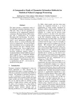
Instead of technological scheme we can show structure of the simulated process on the process flow
diagram we have created in HYSYS (Fig. 1). The feed is compressed to 2.3 MPa, cooled to 38 °C using cooling
water (E-1A), and to -26 °C using refrigerant (E-1B), before entering the flash vessel, (S-1), at 2.1 MPa. Its
vapor effluent and liquid product are heated (E-2A, E-2B), to 27 °C. The latter enters the flash vessel, (S-2), at
1
Jaroslav Poživil,Prague Institute of Chemical Technology, Dept. of Informatics and Control Engineering, Technická 1905, 166 28 Praha 6,
Czech Republic, tel. +420/224 354 259, fax +420/224 311 082,
(Recenzovaná a revidovaná verzia dodaná 9. 9. 2004)
254
Acta Montanistica Slovaca Ročník 9 (2004), číslo 3, 254-257
2.05 MPa. Its liquid effluent is fed to the distillation column, K-1, which is designed to remove most of the
propane in the overhead stream. It has twelve theoretical trays (not counting reboiler and condenser), with the
feed to the fourth tray from the top, and recovers 99 % of nC
5
in the bottom products and 99 % of nC
3
in the
distillate.
Fig. 1 Process flow diagram for the natural gas processing
Simulation Model
The simulation is built using these basic steps:
1. Create a unit set.
2. Choose a property package (we used Peng-Robinson's variant of Redlich-Kwong equation).
3. Select the components.
4. Create and specify the feed streams.
5. Install and define the unit operations prior to the column (Because we are interested only in how much
energy is required to cool or heat a process stream we used a simplified model of heat exchanger
COOLER for E-1A, E-1B and HEATER for E-2A, E-2B. For modeling of flash vessels S-1, S-2 we
used model SEPARATOR that splits the two-phase inlet stream into its vapor and liquid phases, into
one vapor and one liquid product stream.)
6. Install and define the column.
Installing the column is the most difficult step of building simulation model, because multi-stage
fractionation tower is the most complex unit operation that HYSYS simulates. It consists of a series of
equilibrium or non-equilibrium flash stages and has many parameters. For K-1 we used model DISTILLATION
COLUMN. It is a special type of subflowsheet that contains equipment and streams, and exchanges information
with the parent flowsheet through the connected internal and external streams. In general, it has three degrees of
freedom we can use for fruition of desired component separation - a combined mole percentage of nC
5
and nC
6
at least 75 % in the liquid product. However, by specifying zero overhead liquid flow (full reflux condenser) one
degree of freedom was eliminated. For the two remaining specifications from more than 25 available specs we
examined column reflux ratio, column component flow rate and column component fraction. The reflux ratio is
defined as the ratio of the liquid returning to the tray section divided by the total flow of the products.
Component flow rate allows specifying the flow rate of any component, or the total flow rate for any set of
components for the flow leaving any stage. Component fraction allows specifying the mole, mass or volume
fraction in the liquid or vapor phase for any stage.
Tab. 2: Molar Flow Rates of the Gas, and Liquid Product Streams (in kgmole/h)
Model A Model B
Component
Gas
(stream ZP)
Liquid
(stream S11)
Gas
(stream ZP)
Liquid
(stream S11)
N
2
95.7 0 95.7 0
C
1
3754 0 3754 0
C
2
395.1 0 395.1 0
C
3
186.4 0 186.4 0
nC
4
53.4 10.5 53.5 10.5
nC
5
5.1 20.7 5.1 20.7
nC
6
0.9 14.1 0.9 14.1
Total 4490.6 45.4 4490.6 45.4
255
Jaroslav Poživil: Heat-Integrated Design for Natural Gas Processing
We have built two models. In model A we have determined as default specifications reflux ratio and
component fraction – combined mole percentage of C1 – C3 in overhead products. In model B we have
determined as default specifications reflux ratio and component flow rate – molar flow of n-Butane in overhead
products. The optimal reflux ratio was found in both models 5, the calculated C1 – C3 fraction was 71.6 % and
the calculated flow of n-Butane was 21.1 kgmole/h.
Composition of both gaseous and liquid products satisfies requirements of problem (see Tab. 1) and is
represented in Tab. 2
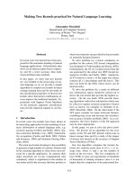
Heat-Integrated Process
Process flow diagram of heat-integrated process we have created in HYSYS is shown in Fig. 2. Structure of
the process was modified so that heat exchangers for heating of outlet streams of the first separator S-1
economize heat of gas heated in compressor. It was necessary to use the full value HEAT EXCHANGER
weighed design model that calculates the overall exchanger UA (product of the overall heat transfer coefficient
and the total area available for heat transfer). In this configuration, the hot stream, S2, has supply and target
temperatures of 73
o
C and - 26
o
C, and the two cold streams, each have supply and target temperatures of - 26
o
C
to 27
o
C, respectively. The hot stream is split and used to heat two cold streams, with a minimum approach
temperature difference of 10
o
C. The split ratio is chosen to obtain isothermal mixing in the mixer, M-1 with the
help of ADJUST operation that
Fig. 2 Process flow diagram for heat-integrated process
varies the ratio of the outlet stream flow of TEE operation D-1 to meet the required zero temperature
difference that is calculated in HYSYS SPREADSHEET operation. Tab. 3 compares the energy requirements of
the original design with the heat integrated design. The latter has no external heating requirements (apart from
the column K-1), and its refrigeration load is only 28 % of that of the original design. Energy saving makes up
approx. 3 MW refrigeration.
Tab. 3: Comparison of the energy requirements in MW of the original design with the heat integrated design
Initial Design Heat-Integrated Design
Exchanger
Refrigerant Cooling Water Steam Refrigerant Cooling Water Steam
E-1A - 2.01 - - 2.01 -
E-1B 4.14 - - 1.14 - -
E-2A - - 2.70 - - -
E-2B - - 0.29 - - -
Total 4.14 2.01 3.99 1.14 2.01 0
This work has been supported by the Ministry of
Education of the Czech Republic (program No.
MSM 223400007).
256
Acta Montanistica Slovaca Ročník 9 (2004), číslo 3, 254-257
257
References
[1] Seider, W. D., Seader, J. D., Lewin, Daniel R.: Process Design Principles - Synthesis, Analysis, and
Evaluation, John Wiley, NY, 1999
[2] Himmelblau D.M.: Basic Principles and Calculations in Chemical Engineering, 2nd ed. Prantice Hall,
Englewood Cliffs, NJ (1967)
[3] HYSYS.Process 2.0 Documentation, Hyprotech, Inc., AEA Group, Calgary, 2000 (CD-ROM)