- Trang chủ >>
- Khoa Học Tự Nhiên >>
- Vật lý
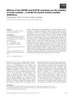
Role of an electrolyte and substrate on the stability of porous silicon
Bạn đang xem bản rút gọn của tài liệu. Xem và tải ngay bản đầy đủ của tài liệu tại đây (449.93 KB, 9 trang )
Physica E 28 (2005) 264–272
Role of an electrolyte and substrate on the stability
of porous silicon
Shailesh N. Sharma
Ã
, R.K. Sharma, S.T. Lakshmikumar
Materials Division, National Physical Laboratory, Dr. K. S. Krishnan Marg, New Delhi-110012, India
Received 14 March 2005; accepted 21 March 2005
Available online 6 June 2005
Abstract
Porous silicon (PS) layers were prepared by anodization on polished and textured substrates of (1 0 0) Si for a fixed
anodization time at different current densities in different HF-based electrolytes. Highly stable, mechanically strong,
hydrogen-passivated surface and thick porous silicon films have been obtained using HF:ethanol-based electrolyte on
textured silicon substrates. Porous silicon formed using HF:ethanol as an electrolyte exhibits superior properties
compared to porous silicon formed using HF:H
2
O
2
-based electrolyte at the same current density, time of anodization
and type of substrate. Porous silicon films formed on textured substrates exhibits higher porosity and photoluminescence
efficiency, negligible PL decay, better mechanical strength, adherence to the substrate, non-fractured surface
morphology and lower stress compared to porous silicon formed on polished silicon substrates at the same current
density for both ethanol and H
2
O
2
-based electrolytes, respectively. Use of textured silicon substrate and ethanol-based
electrolyte is a key parameter for the formation of tailored-made porous silicon films for device applications.
r 2005 Elsevier B.V. All rights reserved.
PACS: 61.43.Gt; 81.05.Rm; 82.45.Gj
Keywords: Porous silicon layers; HF-electrolytes: Si substrates
1. Introduction
Porous silicon (PS) exhibits visible photolumi-
nescence and electroluminescence which has gen-
erated considerable interest [1]. The potential of
porous silicon for various technological applica-
tions such as chemical sensors [2], optoelectronic
devices [3], displays [4] and photodetectors [5] has
been extensively investigated. Recent emphasis has
been on the utilization of the large surface area of
the porous layers for chemical and biological
applications [6]. It is possible to control the degree
of porosity of the porous layers formed by electro-
chemical etching in HF-containing electrolytes
(ethanol, hydrogen peroxide, etc.). However, the
ARTICLE IN PRESS
www.elsevier.com/locate/physe
1386-9477/$ - see front matter r 2005 Elsevier B.V. All rights reserved.
doi:10.1016/j.physe.2005.03.020
Ã
Corresponding author. Tel.: 91 11 25742609 14x2409;
fax: 91 11 25726938, 25726952.
E-mail address:
(S.N. Sharma).
nanoscale structure of PS leads to an enormous
increase in surface area and the presence of large
number of unpaired bonds at the surface which
alter the surface recombination rates and conse-
quently the PL efficiency, surface reactivity and
stability [7]. Several approaches have been tried for
preparing uniformly bonded stable surfaces. The
formation of a high-quality oxide surface layer is
now accepted as a good solution to the formation
of a stable surface and improved luminescent
properties [8]. Embedding the nanocrystalline
silicon particles in an optically transparent med-
ium is another way of isolating the surface from
the ambient and providing a stable luminescence
[9]. Recently, the use of alkyl-terminated mono-
layers as a mean of stabilizing the PS surface has
received attention where Si–H bonds at the surface
during PS formation are replaced by a hydrophilic
alkyl termination [10].
The electrolyte composition is one of the most
important fabrication parameter for well-defined
porous layers. The pore dimensions and porosity
change with different ratios of electrolytes. Var-
ious electrolytes have been used for the fabrication
of porous silicon viz, HF, ethanol, H
2
O
2
and
HNO
3
[1,11,12]. HF is mainly used for the
dissolution of silicon, ethanol is basically used to
reduce the surface tension of the electrolytic
mixture since surface wetting is important for
good pore uniformity. Recently thrust has been
given on H
2
O
2
-based electrolytes preferably as an
oxidizing agent [12]. The photochemical etching
method with H
2
O
2
solution does not generate a
toxic material unlike in the case of HNO
3
[11].
Moreover, the addition of H
2
O
2
to the etching
mixture raises the pH of the solution and produces
ideal Si surfaces terminated with Si–H bonds thus
resulting in a homogeneous PS surface with low
defect density [12].
Recently, we have demonstrated by means of
high-resolution XRD studies that texturization of
silicon surface is an effective method for the
formation of stable and thick porous silicon films
[13]. In this paper, using PL decay as a probe, we
are evaluating the degradation of stability of PS on
electrolyte (HF–C
2
H
5
OH and HF–H
2
O
2
) and
current density formed on textured and polished
Si substrates, respectively. The emphasis is mainly
on the development of PS with high and stable PL,
control of pore size distribution and therefore a
better control on the formation process.
2. Experimental
Boron-doped p-type Si wafers of (1 0 0) orienta-
tion, 8–10 ohmcm resistivity and 400 mm thickness
were used for preparing PS. The wafers were
polished in 40% NaOH for 2 min. These wafers
were textured using 2% NaOH at 85 1C for 30 min.
For forming the back contact, Ag–Al paste was
screen printed on the wafer and dried at 250 1C.
The wafer was then heated to 750 1C for 2 min in
an IR furnace. PS was formed by the standard
anodization process using Si as the anode and Pt as
the counter electrode in an acid resistant container.
The anodization was carried out at 20–50 mAcm
À2
for 30 min, in two different electrolytes. The first is
a mixture of HF and C
2
H
5
OH (1:1 by volume)
which is almost universally used [1] and would be
abbreviated as electrolyte A. The second is a
mixture of HF and H
2
O
2
(1:1 by volume) which
was extensively used by Nafeh et al. [12] and would
be abbreviated as electrolyte B. After the anodiza-
tion, the films were washed in deionized water and
ethanol and dried in nitrogen. The samples were
subjected to continuous agitation in an ultrasonic
cleaner to evaluate the speed with which the sample
is destroyed. The weight of the sample is con-
tinuously monitored. The PL was measured using a
home assembled system consisting of a two-stage
monochromator, a photomultiplier tube (PMT)
with a lock-in amplifier for PL detection, and an
Ar
+
ion laser operating at 488 nm and 5 mW
(corresponding to 0.125 W cm
À2
) for excitation in
all the measurements. Decay of PL intensity has
been used as a measure of the stability of the
surface bond configurations [7]. For PL decay
studies, the sample was continuously exposed to
the laser radiation and PL measurements were
carried out at regular intervals.
3. Results and discussion
Good porous silicon films exhibiting high
photoluminescence intensity could be formed on
ARTICLE IN PRESS
S.N. Sharma et al. / Physica E 28 (2005) 264–272 265
both textured and polished substrates at various
current densities corresponding to both electro-
lytes A and B, respectively. The porosity (45–80%)
and thickness (12–96 mm) of PS films were
estimated from gravimetric measurements [14].
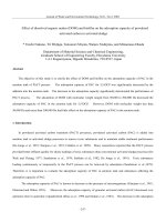
Fig. 1 shows porosity values as a function of I
d
for PS films formed on textured and polished
substrates corresponding to both electrolytes A
and B, respectively. As shown in Fig. 1, porosity of
PS films increases with increase in current density.
As evident from Fig. 1, PS films corresponding to
electrolyte B exhibits higher porosity as compared
to the corresponding films of electrolyte A for both
textured and polished substrates.
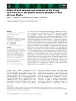
Fig. 2(A) shows the weight loss of PS films
prepared using electrolyte A at different I
d
,asa
function of time of ultrasonic treatment. There is a
substantial weight loss of PS samples on polished
substrates when subjected to an ultrasonic treat-
ment for an hour by which time the entire porous
layer has been removed and the loss of weight
saturates. However, for textured PS films, the
weight loss is marginal. The rate of weight loss
increases with increase in I
d
and this effect is felt
more on PS films prepared on polished substrates.
Results of weight loss for PS films prepared
using electrolyte B are shown in Fig. 2(B). In this
case some loss is observed for textured samples
also. However, the rate of weight loss increases
with I
d
and is much higher for the untextured
samples (Fig. 2(B)).
Typical PL curves for PS films formed at
different current densities I
d
($20, 35 and
50 mA cm
À2
) on textured and polished substrates
corresponding to electrolytes A and B are shown
in Figs. 3(A) and (B). As evident from Figs. 3(A)
and (B), the absolute PL intensity is higher for the
porous silicon formed on textured substrates and
for PS films corresponding to electrolyte B owing
ARTICLE IN PRESS
10 20 30 40 50
40
50
60
70
80
(d)
(c)
(b)
(a)
Porosity (%)
Current Density I
d
(mA cm
-2
)
Fig. 1. Porosity of PS as a function of current density (I
d
); (a)
textured substrate, electrolyte B; (b) polished substrate,
electrolyte B; (c) textured substrate, electrolyte A; (d) polished
substrate, electrolyte A.
0204060
0.3450
0.3455
0.3460
0.3465
0.3470
0.3475
0.3480
0.3485
(c)
(e)
(f)
(b)
(d)
(a)
Weight Loss (gms)
Time of Ultrasonic treatment (mins.)
0
20
40 60
0.3450
0.3455
0.3460
0.3465
0.3470
0.3475
0.3480
0.3485
0.3490
(b)
(d)
(e)
(f)
(a)
(c)
Weight Loss (gms)
Time of ultrasonic treatment
(
mins.
)
(A)
(
B
)
Fig. 2. Weight loss of porous silicon samples prepared at
different current densities (I
d
) for (A) electrolyte A and (B)
electrolyte B; (a) textured substrate, I
d
¼ 20 mA cm
À2
; (b)
polished substrate, I
d
¼ 20 mA cm
À2
; (c) textured substrate,
I
d
¼ 35 mA cm
À2
; (d) polished substrate, I
d
¼ 35 mA cm
À2
; (e)
textured substrate, I
d
¼ 50 mA cm
À2
and (f) polished substrate,
I
d
¼ 50 mA cm
À2
.
S.N. Sharma et al. / Physica E 28 (2005) 264–272266
to its higher porosity. Fig. 3(A) shows that with
increase in I
d
from 20 to 50 mA cm
À2
for electro-
lyte A, the PL peak position shifts towards low-l
side for PS films formed on both textured and
polished substrates. Similarly, for PS samples
corresponding to electrolyte B, the blue-shift of
the PL peak position is more prominent with
the PL peak being at $650 nm as compared to
610 nm for PS films prepared on textured sub-
strates corresponding to electrolyte A at higher
I
d
$50 mA cm
À2
(Fig. 3(B)). This trend is quite
prominent for PS films formed on textured
substrates as compared to the corresponding films
formed on polished substrates for both electrolytes
A and B, respectively (Figs. 3(A) and (B)). These
results are in accordance with quantum confine-
ment effects [1]. It is known that the peak position
of the PL intensity is blue shifted when HF-H
2
O
2
is used as the electrolyte [15]. A marginal shift in
PL peak position towards low l side is also
observed upon texturization (Figs. 3(A) and (B)).
Visual observation shows that the porous silicon
films corresponding to electrolyte A formed on
textured surfaces appear more uniform and strong
as compared to the corresponding films prepared
using electrolyte B. The PS films at higher current
densities (I
d
X35 mA cm
À2
) on polished substrates
shows a break off in PL curves as these films
are powdery in nature and hence unstable corre-
sponding to both electrolytes A and B. PS
films prepared using B are more powdery in nature
and shows peeling-off tendency particularly for
films prepared on polished substrates. This is
even more obvious for films formed at higher I
d
(X50 mA cm
À2
).
Decay of PL intensity is a good indication of the
stability of porous silicon particularly of the
surface bond configurations [3,16].InFig. 4(A),
decay of the PL intensity at the peak wave-
length due to exposure to the laser radiation
for porous silicon films formed at different I
d
¼
ð20250 mA cm
À2
Þ on textured and polished silicon
substrates for electrolyte A are compared. Simi-
larly, the corresponding PL-decay curves for
electrolyte B are shown in Fig. 4(B). The PL peak
position was recorded for different times corre-
sponding to a fixed wavelength. As shown in Figs.
4(A) and (B), significant decay of the PL intensity
is observed for PS films formed on polished
substrate and the rate of decay increases with
increase in I
d
. This is observed for both A and B-
based electrolytes with the rate of PL decay being
higher for electrolyte B as compared to electrolyte
A at all current densities. However, for PS films
formed on textured silicon, no PL decay was
observed when ethanol was used as an electrolyte
and a very marginal decay was noted when H
2
O
2
-
based electrolyte is used (Figs. 4(A) and (B)). To
ARTICLE IN PRESS
0
1
2
3
4
5
6
7
(a)
(f)
(e)
(d)
(c)
(b)
PL Intensity (a.u.)
500 550 600 650 700 750 800
0.0
0.5
1.0
1.5
2.0
2.5
3.0
3.5
4.0
(d)
(c)
(e)
(f)
(a)
(b)
PL Peak Intensity (a.u.)
Wavelength (nm)
500 550 600 650 700 750 800
Wavelength (nm)
(A)
(B)
Fig. 3. PL spectra of porous silicon samples prepared at
different current densities (I
d
) for (A) electrolyte A and (B)
electrolyte B; (a) textured substrate, I
d
¼ 20 mA cm
À2
; (b)
polished substrate, I
d
¼ 20 mA cm
À2
; (c) textured substrate,
I
d
¼ 35 mA cm
À2
; (d) Polished substrate, I
d
¼ 35 mA cm
À2
(e)
textured substrate, I
d
¼ 50 mA cm
À2
and (f) polished substrate,
I
d
¼ 50 mA cm
À2
.
S.N. Sharma et al. / Physica E 28 (2005) 264–272 267
ensure the reproducibility of this PL decay,
measurements were done repeatedly and for
several hours and the PL decay trend was found
to be the same. This is a direct evidence for the
formation of stable surface and correlates with the
superior mechanical stability of porous silicon
formed on textured substrates.
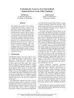
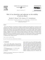
SEM was used to identify the surface morphol-
ogy of the porous silicon formed on textured and
polished Si-substrates at different current den-
sities for electrolytes A and B, respectively. Silicon
nanowires are not visible at these magnifica-
tions. Figs. 5 (A) and (B) show the surface of
porous silicon formed on polished silicon at
I
d
$10 mA cm
À2
corresponding to electrolytes A
and B, respectively. A plain featureless surface
morphology is observed at I
d
$10 mA cm
À2
for
electrolyte A while a cracked surface morphology
is obtained for electrolyte B for the same current
density. Similar observations on the fragility of
thick and highly porous films had been noted
earlier [8,17]. For electrolyte A-based samples at
lower I
d
, lack of cracking indicates lower stress
while the corresponding electrolyte B-based sam-
ple exhibits higher stress. At I
d
¼ 35 mA cm
À2
,
distinct cracking and disintegration is observed for
PS films formed on polished substrates for both
electrolytes A and B with the cracking being more
pronounced for the latter than for the former
(Figs. 5(C) and (D)). The higher current density
results in increased porosity and the inability of
the silicon nanowires to withstand the stress leads
to cracking.
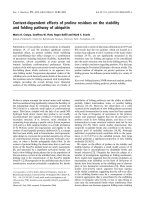
The surface morphology of PS films formed on
textured substrates is significantly different as
compared to polished substrates. Figs. 6(A) and
(B) shows the surface morphology of porous
silicon formed on textured substrates at I
d
¼
35 mA cm
À2
corresponding to electrolytes A and
B, respectively. Here, the smooth surface morphol-
ogy consists of randomly sized and spaced
pyramids homogeneously distributed on the sur-
face. The pyramids appear to be more sharply
separated but no macroscopic cracking is observed
even for electrolyte B-based sample unlike in the
case of PS film formed polished silicon substrate
for the same current density (Figs. 6(A) and (B)).
This surface morphology does not essentially
differ from the textured silicon substrate (not
shown) and is not affected by current density. On
polished silicon substrates, PS layers showed a
tendency to have a mechanically weak structure at
higher current densities (I
d
$50 mA cm
À2
) owing to
its higher porosity resulting in many cracks or
peeling off the film from the substrate. This effect
is more prominent for electrolyte B-based samples
than for electrolyte A-based samples. However,
ARTICLE IN PRESS
0204060
0.0
0.8
1.6
2.4
3.2
4.0
(d)
(c)
(b)
(a)
PL Peak Intensity (a.u.)
Time (mins)
0102030405060
0
1
2
3
4
5
6
(f)
(b)
(e)
(d)
(c)
(a)
PL Intensity (a.u.)
Time
(
mins.
)
(A)
(B)
Fig. 4. PL decay of porous silicon samples prepared at different
current densities (I
d
) as a function of time of laser exposure for
(A) electrolyte A and (B) electrolyte B; (a) textured substrate,
I
d
¼ 20 mA cm
À2
; (b) polished substrate, I
d
¼ 20 mA cm
À2
; (c)
textured substrate, I
d
¼ 35 mA cm
À2
; (d) polished substrate,
I
d
¼ 35 mA cm
À2
; (e) textured substrate, I
d
¼ 50 mA cm
À2
;
and (f) polished substrate, I
d
¼ 50 mA cm
À2
.
S.N. Sharma et al. / Physica E 28 (2005) 264–272268
this is not so in the case of textured substrates. The
cracks observed for PS films formed on polished
substrates for both electrolytes A and B indicates
higher stress and as a consequence, higher PL
decay is observed. Whereas PS samples formed on
textured substrates are marked by smooth surface
morphology, lower stress and consequently, neg-
ligible PL decay.
In order to identify the chemical composition of
our samples, we have investigated the Fourier
transform infrared (FTIR) absorption spectra.
From our FTIR data (Fig. 7) obtained for freshly
ARTICLE IN PRESS
Fig. 5. Scanning electron micrographs of porous silicon prepared on polished substrates at different current densities (I
d
); (A)
I
d
¼ 10 mA cm
À2
, electrolyte A; (B) I
d
¼ 10 mA cm
À2
, electrolyte B; (C) I
d
¼ 35 mA cm
À2
, electrolyte A; (D) I
d
¼ 35 mA cm
À2
,
electrolyte B.
Fig. 6. Scanning electron micrographs of porous silicon prepared on textured substrates at I
d
¼ 35 mA cm
À2
; (A) electrolyte A; (B)
electrolyte B.
S.N. Sharma et al. / Physica E 28 (2005) 264–272 269
prepared samples, it is clear that there are a
number of distinct peaks with different intensities.
Figs. 7(a) and (b) shows FTIR absorption spectra
for PS samples prepared using electrolyte A at
I
d
¼ 20 mA cm
À2
on textured and polished sub-
strates, respectively. PS films prepared on textured
substrates exhibit mainly Si–H related modes at
$2105 cm
À1
due to Si–H stretching mode [18],
910 cm
À1
due to Si–H
2
scissors or Si–H
3
symmetric
or antisymmetric deformation [18,19], 817 and
660 cm
À1
due to Si–H
2
and Si–H wagging [19,20]
while for Si–O related modes are marked by a
broad hump at $1110 cm
À1
due to a bulk
interstitial Si–O–Si asymmetric stretching mode
[18]. However, PS films prepared on polished
substrates exhibits mainly Si–O-related peaks with
a doublet showing peaks at $2256 cm
À1
which is
attributed to Si–H stretching modes when the
silicon is backbonded to oxygen atoms [21] and at
$2117 cm
À1
due to Si–H stretching mode, broad
peak at $1192 cm
À1
and a satellite peak at
$1010 cm
À1
due to Si–O–Si stretching mode and
a weak contribution at $879 cm
À1
due to non-
stretching Si–H modes [20] and no signal of Si–H
wagging modes between 600 and 700 cm
À1
was
observed. It is worthwhile to note that there is no
signature of any O atoms backbonded to Si–H
related mode at $2250 cm
À1
for PS films prepared
on textured substrates (Fig. 7(a)). Another inter-
esting difference noted in the FTIR spectra of PS
films using electrolyte A prepared on textured and
polished substrates is the shift of Si–O related
mode from 1110 to 1192 cm
À1
which indicates
increase in the oxidation state (x) of the SiO
x
species [22]. For H
2
O
2
-based (B) samples formed
on textured substrates, the FTIR spectra
(Fig. 7(c)) shows characteristic peaks of both
Si–H and Si–O-related modes with a doublet
comprising of peak at $2256 cm
À1
(O backbonded
to Si in SiH stretching mode) and at $2117 cm
À1
(SiH stretching mode), a distinct broad peak at
$1215 cm
À1
(Si–O–Si) stretching mode, a broad
peak doublet comprising of peaks at $940 and
840 cm
À1
associated with SiH
2
wagging and
bending modes and a shoulder at $650 cm
À1
due
to Si–H wagging modes, respectively. However,
for the corresponding PS sample formed on
polished substrate, the FTIR spectrum (Fig. 7(d))
exhibits mainly Si–O-related modes at 2250 cm
À1
(O backbonded to SiH mode), a broad peak
comprising of peaks at $1161 and 1018 cm
À1
(Si–O–Si stretching mode) with weak contribu-
tions at $880 and 805 cm
À1
(Si–H-related bending
and wagging modes). Here in Fig. 7(d), the notable
feature is the absence of Si–H stretching at
$2100 cm
À1
and Si–H wagging at $630 cm
À1
.
Thus, silicon–hydrogen-related modes are stronger
for PS samples prepared on textured substrates
while silicon–oxygen-related modes are stronger
for the corresponding films prepared on polished
substrates for the same current density and
electrolyte. The effect of oxidation is felt more
for H
2
O
2
-based PS films particularly formed on
polished substrates as compared to ethanol-based
PS films. From the above results, it can be
conjectured that there is a change in the surface
passivation from hydrogen to oxygen-like species
as we go from textured to polished substrate for
PS films formed at same current density
(I
d
$20 mA cm
À2
) for both the electrolytes A and
B, respectively. In case of H
2
O
2
-based PS films (B),
a significant blue shift in PL spectra as compared
to the corresponding ethanol based films could be
due to the enhanced oxidation of surface of
nanocrystalline Si resulting in an increase of SiO
x
thickness surrounding the Si-core. Oxidation of
ARTICLE IN PRESS
2500 2250 2000 1750 1500 1250 1000 750 500
1.0
1.5
2.0
2.5
3.0
3.5
(d)
(c)
(b)
(a)
Absorbance (a.u.)
Wavenumber (cm
-1
)
Fig. 7. FTIR absorption spectra of porous silicon prepared at
current density I
d
¼ 20 mA cm
À2
; (a) textured substrate,
electrolyte A; (b) polished substrate, electrolyte A; (c) textured
substrate, electrolyte B; (d) polished substrate, electrolyte B.
S.N. Sharma et al. / Physica E 28 (2005) 264–272270
nanocrystalline Si causes shrinkage of the Si-core
due to the breaking of Si–Si bonds resulting in a
blue-shift in PL spectra [11]. However, apart from
interpretation in terms of quantum confinement in
silicon clusters that decrease in size upon oxida-
tion, the PL blue shift can also be related to Si–O
species or due to defects and the silica networks on
which OH groups are absorbed as suggested by
others [23]. These results are in accordance with
our PL and SEM studies where a significant PL
decay and cracked surface morphology was
observed for PS films formed on polished sub-
strates which underlines the importance of tex-
tured substrates and ethanol-based PS films which
exhibits stable PL, smooth surface morphology
and H-passivated surfaces.
Previous measurements showed that using H
2
O
2
in a HF-based electrolytic mixture results in the
termination of Si surfaces mainly with silicon-
monohydrides leading to the formation of stable
and low defect density PS films [12]. However,
contrary to other studies, we have found that
ethanol-based PS films formed on textured sub-
strates are relatively more mechanically strong,
stable, stress-free and highly passivated with
hydrogen than the corresponding H
2
O
2
-based PS
films as elucidated by our weight loss measure-
ments, PL, SEM and FTIR studies. It seems that
the improved luminescent properties of our PS
films is more an artifact of the substrate (textured
one) rather than that of the electrolyte alone. On
the textured surface, the nucleation of nanopores
is preferentially initiated at the boundaries be-
tween the pyramids. This would be assisted by the
slower pore growth [23] on the denser /111S
faceted surfaces compared to the /100S surface
exposed at the boundaries. This may lead to
partial merging of nanopores and the formation of
a high porosity region which can deform and
release the stress at dimensions small enough to
prevent macroscopic crack formation and fragility.
Thus high porosity of PS films formed on textured
substrates can be explained. However, in case of
PS films formed on polished substrates, the etching
is not preferential but random thus resulting in
lower porosity of PS layers. However, the proper
choice of both the substrate (textured) and the
electrolyte (ethanol-based) in conjunction can have
a profound effect in improving the luminescent
properties and stability of porous silicon films.
4. Conclusions
The visual observation of mechanically strong,
stable surface bond configuration, smooth surface
morphology and hydrogen-passivated PS surfaces
essentially conforms the viability of textured
substrates and ethanol-based electrolyte as a
requisite condition for the formation of highly
luminescent, thick and stable porous silicon films.
Porous silicon using ethanol-based electrolyte is
superior to porous silicon formed using H
2
O
2
-
based electrolyte at the same current density on
both textured and polished substrates, respec-
tively. A proper choice of a substrate and an
electrolyte are essential for the formation of highly
porous silicon films with lower fragility, superior
stability and long-term usability.
Acknowledgements
We thank Director NPL for permission to
publish this work supported by CSIR network
project on custom tailored special materials. RKS
thanks CSIR for providing a research associate-
ship. We acknowledge the help of Dr. Ramkishore
and Shri. K.N. Sood for SEM work and of Dr.
V.K. Kaul (CEL) for sample preparation.
References
[1] L.T. Canham, Appl. Phys. Lett. 57 (1992) 1046.
[2] V.S.Y. Lin, K. Motesharie, K.P.S. Dancil, M.J. Sailor,
M.R. Ghadiri, Science 278 (1997) 840.
[3] B. Hamilton, Semicond. Sci. Technol. 10 (1995) 1187.
[4] V.V. Doan, M.J. Sailor, Science 256 (1992) 1791.
[5] M.J. Sailor, J.L. Heinrich, J.M. Lauerhaas, in: P.V.
Kamat, D. Meisel (Eds.), Semiconductor Nanocrystals,
Elsevier, New York, 1996, p. 103.
[6] M.P. Stewart, J.M. Buriak, Adv. Mater. 12 (2000) 859.
[7] S.T. Lakshmikumar, P.K. Singh, J. Appl. Phys. 92 (2002)
3413.
[8] A.G. Cullis, L.T. Canham, P.D.J. Calcott, J. Appl. Phys.
82 (1997) 909.
[9] J.L. Heinrich, C.L. Curtis, G.M. Credo, K.L. Cavanagh,
M.J. Sailor, Science 255 (1992) 66.
[10] J.M. Buriak, M.J. Allen, J. Am. Chem. Soc. 120 (1998)
1339.
ARTICLE IN PRESS
S.N. Sharma et al. / Physica E 28 (2005) 264–272 271
[11] N. Yamamoto, H. Takai, Jpn. J. Appl. Phys. 38 (1999)
5706.
[12] Z. Yamani, W.H. Thompson, L. AbuHassan, M.H.
Nayfeh, Appl. Phys. Lett. 70 (1997) 3404.
[13] G. Bhagavannarayana, S.N. Sharma, R.K. Sharma, S.T.
Lakshmikumar, communicated.
[14] O. Bisi, S. Ossicini, L. Pavesi, Surf. Sci. Rep. 38 (2000) 1.
[15] Z. Yamani, S. Ashhab, A. Nayfeh, W. Thompson, M.
Nayfeh, J. Appl. Phys. 83 (1998) 3929.
[16] P.K. Singh, S.T. Lakshmikumar, Semicond. Sci. Technol.
17 (2002) 1123.
[17] S.N. Sharma, R. Banerjee, S. Chattopadhyay, A.K. Barua,
Proceedings of the 11th International Workshop on the
Physics of Semiconductor Devices (IWPSD) 2001, Allied
Publishers Limited, p. 1444.
[18] W.H. Thompson, Z. Yamani, L. AbuHassan, O. Gurdal,
M. Nayfeh, Appl. Phys. Lett. 73 (1998) 841.
[19] G. Belomoin, J. Therien, M. Nayfeh, Appl. Phys. Lett. 77
(2000) 779.
[20] D.R. Kwon, S. Ghosh, C. Lee, Mater. Sci. Eng. B (2003) 1.
[21] V.M. Dubin, F. Ozanam, J N. Chazalviel, Thin Solid
Films 255 (1995) 87.
[22] S.N. Sharma, R. Banerjee, A.K. Barua, Curr. Appl. Phys.
3 (2003) 269.
[23] H. Tamura, M. Ruckschloss, T. Wirschem, S. Veprek,
Appl. Phys. Lett. 65 (1994) 1537.
ARTICLE IN PRESS
S.N. Sharma et al. / Physica E 28 (2005) 264–272272