Circuit design with HDL Chapter 5 Dataflow modeling (Expression) ppt
Bạn đang xem bản rút gọn của tài liệu. Xem và tải ngay bản đầy đủ của tài liệu tại đây (1.44 MB, 24 trang )
CHAPTER 5: DATAFLOW MODELING
Lecturer: Ho Ngoc Diem
NATIONAL UNIVERSITY OF HO CHI MINH CITY
UNIVERSITY OF INFORMATION TECHNOLOGY
FACULTY OF COMPUTER ENGINEERING
Agenda
Chapter 1: Introduction
Chapter 2: Modules and hierarchical structure
Chapter 3: Fundamental concepts
Chapter 4: Structural modeling (Gate & Switch-level modeling)
Chapter 5: Dataflow modeling (Expression)
Chapter 6: Behavioral modeling
Chapter 7: Tasks and Functions
Chapter 8: State machines
Chapter 9: Testbench and verification
Chapter 10: VHDL introduction
2
Content
Dataflow modeling
Continuous assignment
Expression, operator, operands
Design examples
3
Dataflow model
For complex design: number of gates is very large
-> need a more effective way to describe circuit
Dataflow model: Level of abstraction is higher than gate-
level, describe the design using expressions instead of
primitive gates
Circuit is designed in terms of dataflow between register,
how a design processes data rather than instantiation of
individual gates
RTL (register transfer level): is a combination of dataflow
and behavioral modeling
4
Continuous assignment
Drive a value onto a net
assign out = i1 & i2; //out is net; i1 and i2 are nets
Always active
Delay value: control time when the net is assigned value
assign #10 out = in1 & in2; //delay of performing computation,
//only used by simulator, not synthesis
Left-hand side
Right-hand side
Net (vector or scalar)
Bit-select or part-select of a vetor net
Concatenation of any of the above
Net, register, function
call (any expression that
gives a value)
5
Continuous assignment
Examples:
wire out = in1 & in2; //scalar net
//implicit continuous assignment, declared only once
assign addr[15:0] = addr1_bits[15:0] ^ addr2_bits[15:0]; //vector net
assign {c_out, sum[3:0]} = a[3:0] + b[3:0] + c_in; //concatenation
module adder (sum, carry_out, carry_in, ina, inb);
output [3:0] sum;
output carry_out;
input [3:0] ina, inb;
input carry_in;
wire carry_out, carry_in;
wire [3:0] sum, ina, inb;
assign {carry_out, sum} = ina + inb + carry_in;
endmodule
6
Question: What shall be the result of the following assignment?
(1) wire [3:0] y;
assign y[3:0] = -3;
(2) wire [3:0] y;
assign y[3:0] = 2’b10;
(3) wire [3:0] y;
assign y[3:0] = 6’b111000;
(4) wire [3:0] y;
assign y[3:0] = 1’b0;
(5) wire [3:0] y;
assign y[3:0] = 1’bx;
(6) wire [3:0] y;
assign y[3:0] = 4’bx;
(7) wire [3:0] y;
assign y[3:0] = 4’b1;
In your program, always make bit
width of left-hand side and right-
hand side equal
Examples
Continuous Assignment
7
A sample answer
(1) wire [3:0] y;
assign y[3:0] = -3;
(2) wire [3:0] y;
assign y[3:0] = 2’b10;
(3) wire [3:0] y;
assign y[3:0] = 6’b111000;
(4) wire [3:0] y;
assign y[3:0] = 1’b0;
(5) wire [3:0] y;
assign y[3:0] = 1’bx;
(6) wire [3:0] y;
assign y[3:0] = 4’bx;
(7) wire [3:0] y;
assign y[3:0] = 4’b1;
There may be
tool dependency
on these result.
y = 4’b1101
y = 4’b0010
y = 4’b1000
y = 4’b0000
y = 4’b000x
y = 4’bxxxx
y = 4’b0001
Continuous Assignment
Examples
8
Continuous Assignment
Because the assignment is done always, exchanging the
written order of the lines of continuous assignments has no
influence on the logic
Common error
- Not assigning a wire a value
- Assigning a wire a value more than one
Target (LHS) is NEVER a reg variable
9
Delay
Regular assignment delay
Implicit continuous assignment delay
Net declaration delay
10
Expression: Operands
Constant number or string
Parameter
Net
Variable (reg, integer, time, real, realtime)
Array element
Bit-select or part-select (not for real, realtime)
Function call that returns any of the above
Constant
Data types
11
Expression: Operators
Arithmetic
+ - * / % **
Logical
! && ||
Logical equality
== !=
Case equality
=== !===
Bitwise
~ & | ^ ^~ (or ~^)
Relational
< > >= <=
Unary reduction
& ~& | ~| ^ ^~ (or ~^)
Shift
<< >> <<< >>>
Concatenation
{}
Replication
{{}}
Condition
?:
Unary
+ -
Ref. book for detail
of each operator!
Operators not
allowed for real
expression
12
Examples of basic operators
Operators
13
Examples of Equality operator
Operators
Examples of Shift operator
14
Logical, Bit-wise, Reduction operator
Operators
15
Operator precedence
16
Bitwise operator
module xor3 (input a, b, c, output y);
assign y = a ^ b ^ c;
endmodule
Concatenation
module add_1bit (input a, b, ci, output s, co);
assign #(3, 4) {co, s} = {(a & b)|(b & ci)|(a & ci), a^b^ci};
endmodule
Conditional operator
module quad_mux2_1 (input [3:0] i0, i1, input s, output [3:0] y);
assign y = s ? i1 : i0;
endmodule
Expression example
17
Relational & Equality operator
module comp_4bit ( input [3:0] a, b, output a_gt_b, a_eq_b, a_lt_b);
assign a_gt_b = (a>b),
a_eq_b = (a==b),
a_lt_b = (a<b);
endmodule
Arithmetic operator
module add_4bit (input [3:0] a, b, input ci, output [3:0] s, output co);
assign { co, s } = a + b + ci;
endmodule
Expression example
18
Combinational circuit
4 to 1 mux
OR
module mux4_1 (out, in1, in2, in3, in4,
cntrl) ;
output out ;
input in0,in1,in2,in3 ;
input [1:0] cntrl;
assign out = (cntrl == 2'b00) ? in0 :
(cntrl == 2'b01) ? in1 :
(cntrl == 2'b10) ? in2 :
(cntrl == 2'b11) ? in3 :
1'bx ;
endmodule
module mux4_1(out, in1, in2, in3 ,in4,
cntrl1, cntrl2);
output out;
input in1, in2, in3, in4, cntrl1, cntrl2;
assign out = (in1 & ~cntrl1 & ~cntrl2) |
(in2 & ~cntrl1 & cntrl2) |
(in3 & cntrl1 & ~cntrl2) |
(in4 & cntrl1 & cntrl2);
endmodule
// Use nested conditional operator
assign out = cntrl1 ? (cntrl2 ? in4 : in3) : (cntrl2 ? in2 : in1);
19
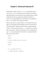
1 bit full adder
Combinational circuit
t1
t2
t3
module adder(cout,s,a,b) ;
output cout;
output [7:0] s ;
input [7:0] a,b ;
assign {cout,s} = a + b ;
endmodule
module fa (input a, b, cin,
output s, cout);
assign s = a^b^cin;
assign cout = (a & b) | (cin & (a^b));
endmodule
• Let’s design 8-bit adder
20
module comparator (result, A, B, greaterNotLess);
parameter width = 8;
parameter delay = 1;
input [width-1:0] A, B; // comparands
input greaterNotLess; // 1 - greater, 0 - less than
output result; // 1 if true, 0 if false
assign #delay result = greaterNotLess ? (A > B) : (A < B);
endmodule
Comparator makes the comparison A ? B
“?” is determined by the input greaterNotLess
and returns true(1) or false(0).
Parameters that may be set
when the module is instantiated.
Combinational circuit
Comparator
21
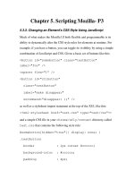
Sequential circuit
4-bit ripple carry counter
22
Sequential circuit
4-bit ripple carry counter
23
Summary
Continuous assignment: main construct in dataflow modeling,
always active
Left hand side of assignment must be a net
Using expression with operators & operands
Delays on a net can be defined in the assign statement,
implicit continuous assignment, or net declaration.
To describe much sophisticated logic easily, procedural
assignment is available in Verilog RTL programming (see later)
24