- Trang chủ >>
- Khoa Học Tự Nhiên >>
- Vật lý
The effect of annealing conditions on the red photoluminescence of nanocrystalline Si/SiO films
Bạn đang xem bản rút gọn của tài liệu. Xem và tải ngay bản đầy đủ của tài liệu tại đây (226.37 KB, 10 trang )
Thin Solid Films 425 (2003) 175–184
0040-6090/03/$ - see front matter ᮊ 2002 Elsevier Science B.V. All rights reserved.
PII: S0040-6090
Ž
02
.
01113-6
The effect of annealing conditions on the red photoluminescence of
nanocrystalline SiySiO films
2
Xiaochun Wu *, Alpan Bek , Alexander M. Bittner , Ch. Eggs , Ch. Ossadnik , S. Veprek
a, aabbb
Max-Planck Institut fuer Festkoerperforschung, Heisenbergstrasse 1, D-70569 Stuttgart, Germany
a
Institut fuer Chemie Anorganischer Materialien, Technische Universitaet Muenchen, Lichtenbergstr. 4, D-85747 Garching, Germany
b
Received 18 June 2002; received in revised form 24 October 2002; accepted 12 November 2002
Abstract
Nanocrystalline Si (nc-Si) embedded in a SiO matrix, fabricated by plasma CVD and a subsequent post-treatment shows a
2
broad red photoluminescence (PL). In this paper, the effects of annealing temperature, atmosphere and time on the red PL from
1.75 to 1.5 eV have been investigated in detail. It is found that the spectral shift and the PL intensity from 1.75 to 1.5 eV show
a strong and unique dependence on annealing conditions. For a PL approximately 1.75 eV, upon 400 8C forming gas annealing,
the spectral shift and the peak intensity versus accumulation annealing times show a novel temporal oscillation. This unique
dependence and the novel temporal oscillation behavior, which have not been reported in porous silicon, exclude nc-Si itself as
the source of the red PL. Instead they favor oxygen thermal donors (TDs)-like defect states as PL centers. This is in consensus
with our earlier results of defect studies using electron spin resonance in this system. Furthermore, two PL centers in this red PL
were distinguished according to their variance in annealing temperature- and time-dependence. The spectral change between 1.5
and 1.75 eV upon annealing conditions can be qualitatively explained by using the formation and annihilation kinetics of two
oxygen TDs-like defect state.
ᮊ 2002 Elsevier Science B.V. All rights reserved.
Keywords: Photoluminescence; Thermal donors; Annealing conditions
1. Introduction
Since the discovery of a strong visible photolumin-
escence (PL) in porous silicon (PS) in 1990
w
1
x
, many
experiments have been carried out in the hope of a
potential application of Si in optoelectronic devices.
Although a large volume of experimental data is avail-
able in the literature, a detailed understanding of the PL
mechanism has not been achieved yet
w
2,3
x
. So far,
mainly two models are proposed to interpret the origin
of the visible PL: (1) pure quantum size effect (QSE)
w
4
x
and (2) surface state model
w
5
x
. As is well-known,
for PL phenomena, two important processes are the
formation of photoexcited carriers (excitation process)
and the radiative recombination of the photoexcited
carriers through PL centers (luminescence process). For
the pure QSE, it is considered that both the excitation
*Corresponding author. Tel.: q49-711-689-1432; fax: q49-711-
689-1709.
E-mail address: (X. Wu).
process and the PL process originate from nanocrystal-
line Si (nc-Si). For the surface state model, it is
considered that the excitation process originates from
nc-Si and the PL process originates from a special
surface state. As for the surface state model, various
surface species such as siloxene
w
6
x
, polysilanes
w
7
x
,
SiH
w
8
x
, Si band-tail states
w
9
x
, interfacial oxide-related
2
defect centers
w
2
x
, nonbridging oxygen hole centers
w
10
x
,
and oxyhydride-like emitters
w
11
x
have been suggested
as the source of the visible PL. Among them, interfacial
oxide-related defect centers are widely accepted, but
still the detailed structures of these centers are unclear
w
2,10–17
x
. Gole et al. even suggested a third model; i.e.
both the light excitation process and the PL process are
due to a surface-bound silanone-based silicon oxyhydri-
de fluorophor, based on their investigations on the origin
of the PL in PS
w
11–13
x
. Recently, studies from Wolkin
et al. seemed to clarify some disputes among the source
of visible PL in PS
w
18
x
. They pointed out that depend-
ing on the size of PS and on the interfacial chemical
176 X. Wu et al. / Thin Solid Films 425 (2003) 175–184
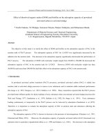
Fig. 1. Evolution of PL Spectra after 870 8C FG annealing of (a) 15
min; (b) 4 h 15 min; (c) 5 h 15 min; (d) 6 h 15 min; and (e) 6h
32 min. Inset: the integrated PL intensity and the peak energy vs.
annealing time.
environment, either PS itself or the Si_ O surface state
can be the source of the visible PL.
In addition to the studies of the visible PL in PS
produced by the wet electrochemical method, studies of
nc-Si fabricated by various dry chemical techniques
have also been carried out in order to understand the
PL mechanism
w
19–21
x
. Veprek and Wirschem have
reported the red PL approximately 1.5 eV in nc-Siy
SiO films produced by plasma CVD and subsequent
2
post-treatment in detail before. Thereby, oxide-related
defect states were suggested to be the possible source
of this red PL
w
22
x
. Later, defect studies using electron
spin resonance (ESR) technique in this system further
showed the correlation of the integrated PL intensity
with the concentration of oxygen thermal donors (TDs)-
related defect states, indicating that this kind of oxygen-
related defect was responsible for the observed red PL
in this system
w
23
x
.
In the present study, we further extend our investiga-
tions to the effects of annealing temperature, atmosphere,
and time on the spectral change of the red PL because
the formation and annihilation kinetics of oxygen TDs
in bulk crystalline Si is both annealing temperature- and
time-dependent. A strong and unique dependence of the
red PL on annealing conditions has been observed
between 1.75 and 1.5 eV. For a PL approximately 1.75
eV, upon 400 8C forming gas annealing, the spectral
shift and the peak intensity versus annealing times show
a novel temporal oscillation. This unique dependence
and the novel temporal oscillation behavior exclude nc-
Si itself as the source of the red PL. Instead they favor
oxygen TDs-like defect states as PL centers. Further-
more, two PL centers in this red PL were distinguished
according to their variance in annealing temperature-
and time-dependence. The spectral change between 1.5
and 1.75 eV upon annealing conditions can be qualita-
tively explained by using the formation and annihilation
kinetics of two oxygen TDs (Si NL8 and Si NL10)-like
defect state.
2. Experiment
The detailed synthesis of Si nanocrystallites by plasma
CVD and post-treatment has been reported previously
w
22
x
. The typical preparation of a sample is as follows:
first, an amorphous Si film is deposited onto a Si (100)
wafer from a pure silane plasma. The film is annealed
under 0.03 mbar of hydrogen flow at 660 8C for 40 min
afterwards to decrease the amount of hydrogen. Then
the film is pre-oxidized under a flow of pure oxygen at
350 8C for a chosen time in order to allow oxygen to
diffuse into the film. Finally, the pre-oxidized film is
annealed at high temperature in a forming gas (FG, 5
mol.% hydrogen in nitrogen) atmosphere for a chosen
time in order to obtain Si nanocrystallites surrounded
by a SiO matrix and to obtain a red PL. Crystallite size
2
and the fraction of nc-Si in the film are controlled by
FG annealing time. The nc-SiySiO film was character-
2
ized with X-ray diffraction (XRD, Siemens Diffracto-
meter D5000). The excitation source for room
temperature steady-state PL spectra was the 325 nm line
of a He–Cd laser (Omnichrome Series 56). The maxi-
mum pump power density of the laser was 0.4 Wycm .
2
PL signals were spectrally resolved with a grating
spectrometer (Spex Model 1681B) and detected by a Si
diode in the lock-in mode. The calibration of the spectral
sensitivity of the whole measuring system was per-
formed using a tungsten standard lamp.
3. Results
3.1. Appearance and spectral changes of the PL upon
high temperature annealing
As mentioned in the preparation procedure section,
the red PL from a nc-SiySiO film could be observed
2
only after several hours of high temperature FG anneal-
ing. One example was given in Fig. 1. After 4 h under
high temperature annealing at 870 8C, the red PL
appears. Its intensity increases upon further annealing,
accompanying a blueshift of the peak energy. After
certain times, the intensity decreases with further anneal-
ing and the peak energy blueshifts to approximately
1.75 eV. The dependence of the integrated PL intensity
and the spectral shift on annealing times is given in Fig.
1 inset. It shows a dominant PL approximately 1.5 eV.
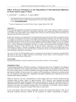
Fig. 2 presents the corresponding variations in the XRD
diagram. Increasing annealing times, due to the oxida-
tion of nc-Si by the oxygen adsorbed in the film in the
previous step, the amount of nc-Si in the film decreases,
177X. Wu et al. / Thin Solid Films 425 (2003) 175–184
Fig. 2. The XRD diagrams after 870 8C FG annealing of (a) 15 min;
(b) 4 h 15 min; (c) 5 h 15 min; (d) 6 h 15 min; and (e) 6 h 32 min,
showing the change in size and amount of nc-Si in the film.
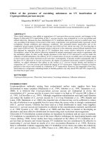
Fig. 3. The peak energy as a function of FG annealing times at anneal-
ing temperatures of (a) 200, 300 and 400 8C and of (b) 500, 600 and
700 8C.
Fig. 4. The normalized PL intensity as a function of FG annealing
times at annealing temperatures of (a) 200, 300 and 400 8C and of
(b) 500, 600 and 700 8C.
accompanying an obvious increase in the amount of
amorphous SiO . Generally, the effect of high tempera-
2
ture FG annealing can be divided into three stages
w
24
x
.
In the first stage, the PL intensity from the nc-SiySiO
2
film increases, and the peak energy shows a blueshift
from 1.3 to 1.55 eV (Fig. 1b–d). During this stage, the
concentration of nc-Si in the film decreases appreciably
and the average dimension of nc-Si also decreases from
approximately 30 to 15 A evaluated using Scherra’s
˚
formula for the XRD measurements (Fig. 2b–d).In
addition, due to the rapid high temperature oxidation,
the color of the film changes from brown to gray. In the
second stage, the PL intensity further increases, while
the peak energy does not show any obvious change. In
Fig. 1, we do not see the second stage, but it has been
observed in many other samples and studied in detail
by Veprek and Wirschem
w
22
x
. At this stage, the nc-Siy
SiO film shows a strong red PL. The peak energy is
2
1.55"0.05 eV, determined by the detailed preparation
conditions of the film. At this stage, the correlation
between the PL intensity and the oxygen TDs concen-
tration from ESR measurements has been demonstrated
w
23
x
. In the third stage, the PL intensity decreases, and
the peak energy blueshifts from 1.55 to approximately
1.75 eV (Fig. 1d–e). During the second and third stage,
the film color shows no observable change. Due to the
variance in the detailed synthesis parameters for the
films, the time range required for the different stages in
different films is also different, though the change trend
of the red PL is similar.
Above we give a general description of the three
stages of the red PL from nc-SiySiO films. Since the
2
first (1.3–1.55 eV) and the second stages (f1.55 eV)
have been reported in detail elsewhere
w
22,24
x
, we will
report here the effects of annealing conditions on the
PL approximately 1.75 eV (in the third stage).
3.2. The influence of FG annealing temperatures on the
PL approximately 1.75 eV
It was found that the PL approximately 1.75 eV
shows interesting dependence on annealing conditions.
Fig. 3 gives the shift of the peak energy vs. annealing
times at different FG annealing temperatures for one
sample. For clarity, the effect of annealing temperatures
at 200, 300 and 400 8C is shown in Fig. 3a, while that
at 500, 600 and 700 8C is presented in Fig. 3b. Fig. 4
gives the corresponding PL intensity change, with the
intensity normalized to that of the starting position. For
each temperature curve, this starting point was obtained
by annealing the film at 700 8C for several minutes.
Below 400 8C annealing, the peak energy redshifts and
the PL intensity increases with increasing annealing
times. The lower the temperature, the slower the redshift
and the increase in intensity. Above 400 8C annealing
178 X. Wu et al. / Thin Solid Films 425 (2003) 175–184
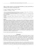
Fig. 5. PL spectra measured after different annealing times at annealing temperatures of (a) 300 8C and (b) 500 8C. Lines with arrow indicate
the direction of spectra variation.
Fig. 6. Correlation between the peak energy and the PL intensity under
FG atmosphere for one sample at different annealing temperatures.
The solid line is a guide to the eye.
(500 and 600 8C), the peak energy first redshifts and
the PL intensity increases; a blueshift up to approxi-
mately 1.75 eV and intensity decrease follows. At 700
8C annealing for a short time, the peak energy remains
unchanged, and the PL intensity shows a small decrease.
Therefore, for the PL approximately 1.75 eV, FG anneal-
ing at lower temperatures ((400 8C) leads to an
increase in PL intensity and to a redshift in peak energy.
FG annealing at intermediate temperatures (400
8C(T-700 8C) results in an increase in intensity and
a redshift in peak energy for short annealing times, but
a decrease in intensity and a blueshift in peak energy
for long annealing times. Short time FG annealing at
high temperatures (f700 8C) causes no appreciable
effect. This indicates that the spectral shift and the
intensity variation of the PL are both temperature- and
time-dependent. Fig. 5a and b depicts the evolutions of
PL spectra at different annealing times for annealing
temperatures 300 and 500 8C, respectively. It can be
seen that for the anneal at 300 8C, during the whole
annealing process (25 h 25 min), the PL gradually
redshifts from 1.75 to 1.59 eV and its intensity also
gradually increases. In the case of 500 8C annealing, the
PL redshifts from 1.70 to 1.63 eV during the first 60
min annealing and the PL intensity reaches its maxi-
mum, then the PL gradually blueshifts from 1.63 to 1.75
eV and its intensity correspondingly decreases from 60
min to 22 h. The redshift of the peak energy at 500 8C
is smaller than that at 300 8C. Therefore, both annealing
temperature and annealing time determine the magnitude
of the spectral shift and of the intensity change.
In addition, a general trend is that PL intensity
decreases (increases) with a blueshift (redshift) of the
peak energy at all annealing temperatures. Fig. 6 dem-
onstrates this correlation between the integrated intensity
and the peak energy using data from 200 to 700 8C (i.e.
data from Figs. 3 and 4). In Fig. 6, instead of annealing
time, the peak energy is chosen as x-axis. The integrated
PL intensity at each annealing time vs. the corresponding
peak energy at the same annealing time is shown. Data
from different annealing temperatures (from 200 to 700
8C) are given in different symbols. From Figs. 3–6, we
can see that the PL can be tuned continuously between
1.5 and 1.75 eV through the control of the annealing
conditions. But the final peak energy of the PL at each
annealing temperature is either approximately 1.75 eV
(500, 600 and 700 8C annealing) or approximately 1.5
eV (300 and 400 8C annealing) for the annealing times
we used. The PL approximately 1.75 eV exhibits itself
better after annealing at higher temperatures for a shorter
time (0700 8C) or at intermediate temperatures (400–
600 8C) for a longer time while the PL approximately
1.5 eV exhibits itself better after annealing at lower
temperatures for a longer time (-400 8C) or at inter-
mediate temperatures for a shorter time (400–600 8C).
The former is thermodynamically more stable than the
latter. This suggests that there exist at least two lumi-
nescent states with different stabilities in annealing
179X. Wu et al. / Thin Solid Films 425 (2003) 175–184
Fig. 7. The PL intensities at 1.75 and 1.46 eV vs. annealing times at
different temperatures with solid-squareqsolid line, solid-circleq
dash line and solid-triangleqdot line representing 1.75 eV at 200,
300 and 400 8C, respectively in (a) and at 500, 600 and 700 8C,
respectively in (b) and with open-squareqsolid line, open-circleq
dash line and open-triangleqdot line denoting 1.46 eV at 200, 300
and 400 8C, respectively in (a) and at 500, 600 and 700 8C, respec-
tively in (b).
Fig. 8. The peak energy (a) and the PL intensity (b) versus annealing
times upon 400 8C annealing in an oxygen (open circle) atmosphere
and in a FG atmosphere (solid square).
temperatures and times. One is located at a lower energy
(f1.5 eV) with a lower thermal stability while the
other is located at a higher energy with a higher thermal
stability (f1.75 eV). The spectral changes from 1.75
to 1.5 eV upon annealing can be explained in the
following two ways: (1) the 1.75 eV PL centers gradu-
ally change to the 1.5 eV PL centers upon annealing;
therefore PL gradually redshifts from 1.75 to 1.5 eV. In
this way, we will observe an increase in the PL intensity
approximately 1.5 eV and a decrease in the PL intensity
approximately 1.75 eV. (2) These two PL centers do
not change to each other upon annealing. They just have
different formation and decay kinetics. If the 1.5 eV PL
centers grow much faster than the 1.75 eV PL centers
or if the 1.5 eV PL centers form while the 1.75 eV PL
centers decay (but do not change to 1.5 eV PL centers),
the whole PL will also redshift. From Fig. 5, we can
see that with increasing annealing time (-60 min), the
PL intensities at 1.75 and 1.5 eV both increase. To see
this more clearly, we further show the normalized PL
intensities at 1.75 and 1.46 eV (a little redshift from 1.5
eV for the better avoidance of a possible overlap of the
two bands) vs. annealing times at different annealing
temperatures in Fig. 7. For 300, 400 and 500 8C
annealing, we can see clearly that during the redshift of
the peak energy (Fig. 3), the PL intensities at 1.75 and
1.46 eV both increase with increasing annealing times,
but the increase rate of PL intensity at 1.46 eV is much
larger than that at 1.75 eV. This means that the redshift
of the PL from 1.75 to 1.5 eV is not caused by the
transformation between these two PL centers, but is due
to the difference in their growth rates. The blueshift of
the PL can be explained using their difference in decay
rates. In Fig. 7b for the case of 500 8C annealing, we
can see clearly that during the blueshift of the peak
energy, the decay rate of PL intensity at 1.46 eV is
faster than that at 1.75 eV. This leads to the blueshift of
the peak energy. On the other hand, slower decay rate
for 1.75 eV PL also means that it is thermodynamically
more stable than 1.5 eV PL. This agrees with the
experimental results. In addition, the redshift of peak
energy via annealing times always accompanies with an
increase in PL intensity while the blueshift of peak
energy accompanies with a decrease in PL intensity.
This means that with the redshift of the peak energy we
have a dominant growth process for both PL centers
while with the blueshift of the peak energy we have a
dominant decay process for them.
3.3. The effect of annealing atmosphere
It is well known that hydrogen plays an important
role in the PL process for PS. The roles of hydrogen
that have been suggested are: (1) the passivation of
dangling bonds
w
25–27
x
; (2) as one of the components
of the luminescence centers
w
11,29
x
; and (3) responsible
for the change of the interfacial environment around Si
crystallites by adsorption and desorption processes
w
11,29
x
.
In order to determine the role of hydrogen in our
case, the annealing atmosphere was changed from FG
to oxygen. Fig. 8 compares the effect of annealing
atmospheres on the red PL. The PL shows similar
redshifts for both atmospheres (Fig. 8a), indicating that
annealing atmospheres have no direct correlation to the
redshift. This further verifies that the redshift corre-
180 X. Wu et al. / Thin Solid Films 425 (2003) 175–184
Fig. 9. The dependence of the peak energy and the PL intensity on
annealing times at 400 8C with (a) first oxygen annealing, then FG
annealing and with (b) first FG annealing, then oxygen annealing.
Open square and triangle for the peak energy and solid square and
triangle for the PL intensity.
Fig. 10. The dependence of the peak energy (solid squareqdash line)
and the PL intensity (open squareqsolid line) on annealing times
upon 400 8C FG annealing.
sponds to the growth process of PL centers. The increase
in PL intensity for the FG atmosphere is however much
larger than that for the oxygen atmosphere (Fig. 8b),
indicating that hydrogen is a much effective passivation
gas to nonradiative combination centers than oxygen. In
order to further distinguish the role of annealing atmos-
pheres, we use a two-step annealing procedure to sepa-
rate the growth process of PL centers and the passivation
process of nonradiative centers. As shown in Fig. 9a,
the peak energy monotonically decreases with the
annealing time by a first oxygen annealing, which
indicates the growth process of PL centers, a subsequent
FG anneal causes a very small redshift in peak energy
but a strong enhancement in PL intensity after a short
time annealing. This strongly supports the passivation
role of hydrogen to nonradiative centers. Fig. 9b presents
a reverse annealing order for another sample. After the
redshift in peak energy reaches its maximum by the first
FG annealing, the subsequent oxygen anneal reduces
the PL intensity accompanying with a very small redshift
in peak energy after short time annealing. This indicates
that instead of passivation of nonradiative centers oxy-
gen annealing increases their concentrations. Since the
redshifts vs. annealing times match quite well after short
time annealing under both atmospheres, we assume that
annealing atmospheres do not influence the growth
process of PL centers, i.e. similar amount of PL centers
for both annealing atmospheres at same annealing times.
However, FG atmosphere reduces the amount of nonra-
diative centers while oxygen atmosphere increases their
amount. The actual PL is determined by both the
concentrations of PL centers and of nonradiative recom-
bination centers. This leads to the much strong enhance-
ment of PL in the case of FG annealing (Fig. 8b).
Therefore, the main role of hydrogen here is the effective
passivation of nonradiative recombination centers.
3.4. The effect of annealing times upon 400 8C annealing
At an annealing temperature of 400 8C, longer time
annealing (010 h) also results in a blueshift of the PL
and in a decrease of its intensity (Figs. 8 and 9). Fig.
10 depicts the dependence of the intensity and the peak
energy on annealing times upon 400 8C. At shorter
annealing times (-10 h), the PL redshifts from 1.68 to
1.51 eV, accompanying an increase in the intensity. With
the prolongation of the annealing time (from 10 to 70
h), the PL blueshifts from 1.51 to 1.7 eV, accompanied
by a decrease in the intensity. This indicates that upon
annealing at 400 8C, the growth rates of PL centers are
much faster than their decay rates. Similar to the cases
for 500 and 600 8C annealing, we see a complete
spectral change process also for 400 8C annealing, i.e.
a redshift of the peak energy accompanying an increase
in PL intensity at short annealing time and a blueshift
of the peak energy accompanying a decrease in PL
intensity at long annealing time. For the case of 400 8C
annealing, the final thermodynamic stable PL is also the
PL approximately 1.75 eV.
3.5. Kinetic oscillations of the red PL upon 400 8C
annealing
It was found that upon 400 8C annealing, during the
decay process of the PL centers (blueshift of the PL),a
short time annealing causes the recovery of the PL
centers (re-redshift of the PL). This leads to the spectral
shift and the peak intensity vs. accumulation annealing
times show temporal oscillations as shown in Fig. 11.
The sample shows a weak PL approximately 1.75 eV
before 400 8C annealing. With increasing annealing
times (-10 h), the PL gradually redshifts from 1.75 to
1.46 eV and its intensity increases by a factor of 18. A
181X. Wu et al. / Thin Solid Films 425 (2003) 175–184
Fig. 11. The peak energy (a) and the PL intensities at 1.75 eV, at 1.46
eV, and at the peak energy (b) vs. annealing times for 400 8C anneal-
ing temperature. A demonstration of the temporal oscillation.
subsequent 18 h annealing blueshifts the PL from 1.46
to 1.59 eV and reduces its intensity by a factor of 2.8.
From this position, annealing at shorter times (-5h)
leads to a redshift from 1.59 to 1.49 eV and to an
increase in the intensity while annealing at longer times
(42 h) results in a blueshift from 1.49 to 1.63 eV and
in a decrease of the intensity. From 1.63 eV, again at
shorter times (-8h), the PL redshifts from 1.63 to
1.49 eV with a 3.5 times increase in the intensity,
whereas at longer times (70 h), it blueshifts from 1.49
to 1.75 eV with an 11 times decrease in the intensity.
From Fig. 11, we obtain the following important results:
(1) it reproduces the 400 8C annealing behaviors we
observed above for other samples (for example in Fig.
10), i.e. a short time growth process and a long time
decay process. (2) During the decay process of PL
centers, the PL centers can recover using a short anneal-
ing time. This makes the spectral shift and the intensity
variation versus accumulation annealing times exhibit
temporal oscillatory behavior. Each oscillation is com-
posed of two time segments, i.e. a shorter time segment
with a redshift in the peak energy and an increase in
intensity and a longer time segment with a blueshift in
the peak energy and a decrease in intensity. In addition,
the increase in intensity and the degree of redshift
decrease with cycling times. (3) As shown in Fig. 11b
point 1 (1.75 eV),2(1.59 eV), and 3 ( 1.63 eV), the
growth of PL centers can be initiated at different peak
energies during the decay process of the PL centers.
This leads to an aperiodic oscillatory behavior. Therefore
the oscillatory behavior is a pure kinetic one.
From III B to D, we have already found that there
exist two PL centers in the red PL. One is approximately
1.5 eV and the other is approximately 1.75 eV. The
actual PL is composed of both. The difference in their
formation and decay kinetics leads to the observed
spectral change for the PL. Therefore, in Fig. 11b, apart
from the PL intensity at peak energy, we also exhibit
the PL intensities at 1.75 and 1.46 eV with annealing
time. We can see that the growth rate of 1.46 eV PL
centers is faster than that of 1.75 eV PL centers. This
difference in the growth rates for these two PL centers
leads to the redshift of the PL. After the concentrations
of PL centers reach maximum, the growth process can
be neglected and the decay process of PL centers
dominates. The decay rate for 1.46 eV PL is faster than
that for 1.75 eV. This difference in the decay rates
results in the blueshift of the PL. We also notice that
for 1.75 eV PL and 1.46 eV PL, their growth rates are
much larger than their decay rates. As seen from Figs.
10 and 11, we know that the PL approximately 1.75 eV
is the final thermodynamic stable state and that the PL
approximately 1.5 eV is a metastable state for 4008
annealing. The existence of this metastable state is one
of the reasons that we can observe the oscillatory
behavior. At this metastable state, the concentration of
PL centers reaches its maximum (at least for the 1.5 eV
PL centers). During the slow decay process, the system
deviates from this metastable state and therefore produc-
es a driving force to go back. Due to the fast growth
rates of the PL centers, we observe their recovery at
short annealing time.
4. Discussion
4.1. The source of the red PL
As outlined in Section 1, two sources are suggested
to be the origin of the visible PL in PS and in nc-Si.
One is nc-Si itself. Another is interfacial defect state. If
the PL is from nc-Si, according to the pure QSE model,
the PL approximately 1.5 eV should be mainly due to
the larger nc-Si while the PL approximately 1.75 eV
should be mainly due to the smaller nc-Si. Then the
continuous redshift of the PL from 1.75 to 1.5 eV should
correspond to the gradual increasing in the average grain
size (assuming a Gaussian size distribution). If this is
the case, with the gradual increasing in the PL intensity
approximately 1.5 eV, the PL intensity approximately
1.75 eV should correspondingly decrease since some of
smaller particles become larger particles. The blueshift
of the PL should be the other way round. However, the
experimental results indicate that during the redshift of
peak energy from 1.75 to 1.5 eV, with the gradual
increasing in the PL intensity approximately 1.5 eV, the
PL intensity approximately 1.75 eV also increases. This
therefore repulses the idea that the distribution of grain
size changes. In addition, XRD diagrams show no
observable change after low temperature annealing, indi-
cating no variations in the nc-Si size and amount. (2)
The spectral oscillation upon 400 8C annealing indicates
182 X. Wu et al. / Thin Solid Films 425 (2003) 175–184
Fig. 12. Isochronal annealing curve for PL intensities at 1.75 and 1.46
eV. The duration of the annealing time was 60 min at each
temperature.
that this oscillation is a pure kinetic one. It can be
initiated at different peak energies during the decay
process of the PL centers. It rules out the structural
phase transition or the size variation of nc-Si itself as
the oscillatory element. Our results therefore exclude
nc-Si itself as the source of the red PL in our case. As
a result, the source of the red PL should be defect-state-
related PL centers.
As mentioned above, our earlier defect studies using
ESR technique have already built up the correlation
between the intensity of PL approximately 1.5 eV and
the concentration of oxygen TDs-like defect state
w
23
x
.
It is known that oxygen TDs widely exist in oxygen-
enriched crystalline silicon under low temperature
annealing (300–550 8C)
w
30–32
x
.Uptonow,17TD
species ((TD) ,1(n(17) have been identified, which
n
develop sequentially upon heat treatment with the more
shallow species being generated later
w
33
x
. From ESR
measurements, individual (TD) cannot be distin-
n
guished, and mainly two signals (Si-NL8 state and Si-
NL10 state) are related to oxygen TDs. The main
features of these two oxygen TDs can be summarized
as follows: (1) the formation process of Si-NL8 state is
normally faster than that of Si-NL10 state. Si-NL8 state
is less stable at long annealing times and at higher
temperatures compared to Si-NL10 state
w
34
x
. (2) The
concentration of oxygen TDs in crystalline Si from ESR
measurements upon low temperature annealing first
increases with annealing time, then reaches a maximum,
and finally decreases
w
34
x
. (3) The important factors
that control the formation of TDs are the annealing
temperature and annealing time. Detailed studies show
that at temperatures below 450 8C the formation rate is
decreased and the saturation concentration of TDs is
less than that for a 450 8C thermal treatment. Above
450 8C the saturation concentration of TDs decreases
with increasing temperature
w
35
x
.
The effect of isochronal annealing (60 min) at differ-
ent temperatures on the PL intensities at 1.75 and 1.46
eV is given in Fig. 12. Here the temperature range for
the increase of the PL intensity further shows a corre-
lation with the formation temperature range of oxygen
TDs in crystalline Si, over the temperature range 300–
550 8C. As shown in Fig. 7a and b, for annealing
temperatures between 300 and 500 8C the PL intensity
approximately 1.46 eV increases much faster than the
PL intensity approximately 1.75 eV whereas above 400
8C the former annihilates much faster than the latter. In
addition, for 500 and 600 8C annealing, the PL intensi-
ties at 1.75 and 1.46 eV vs. annealing times show a
process of increasing, reaching maximum, then decreas-
ing, similar to the annealing behavior of Si-NL8 state
and Si-NL10 state
w
34
x
. Comparing the above features
of the PL centers with those of oxygen TDs, we can
further postulate that the PL approximately 1.75 eV is
mainly due to Si-NL10-like defect states while the PL
approximately 1.5 eV is composed of both Si-NL8- and
Si-NL10-like defect states and is dominated by Si-NL8
states. The red PL consists of these two states. The peak
energy and the PL intensity are determined by the
concentrations of these two components at the corre-
sponding annealing temperature and time.
4.2. The annealing conditions dependence of the red PL
Now we can explain the spectral change of the PL
from 1.75 to 1.5 eV. For a PL approximately 1.75 eV,
upon annealing at lower temperatures (-600 8C), first
both Si-NL8- and Si-NL10-like states grow, but the
former forms much faster, and thus the PL redshifts and
the intensity increases. When the concentration of Si-
NL8-like state reaches its maximum, the redshift and
the increase in the PL intensity also reach a maximum.
Upon further annealing, both states gradually decay.
Since Si-NL8-like states decay faster than Si-NL10-like
states, the PL gradually blueshifts and the PL intensity
also decreases. Finally, only Si-NL10-like states exist
and show a PL approximately 1.75 eV. For lower
annealing temperatures (-400 8C), due to the lower
formation rate, the whole annealing period corresponds
to the growth process of PL centers. For intermediate
temperatures (400–600 8C), we observe a complete
growth, saturation and decay process. From Fig. 6, we
can also see that the degree of the redshift in the peak
energy and the magnitude of the increase in the inte-
grated PL intensity decrease with increasing annealing
temperatures from 400 to 600 8C. This is again due to
the difference in the growth and decay kinetics of these
two states. With increasing annealing temperatures from
400 to 600 8C, the growth rates for Si-NL8- and Si-
183X. Wu et al. / Thin Solid Films 425 (2003) 175–184
NL10-like states both increase, but the former increases
less than the latter (Fig. 7). This causes the difference
in the growth rates of these two states decreasing with
increasing temperatures. Therefore, the degree of the
redshift in the peak energy also decreases with increasing
annealing temperature. On the other hand, with increas-
ing annealing temperatures, the decay rates for these
two states also increase very fast. This leads to the
saturation concentration of these two states decreasing
with increasing temperatures, which agrees with the
dependence of saturation concentration for oxygen TDs
in bulk Si on annealing temperatures
w
35
x
. This explains
the magnitude of increase in the PL intensity decreasing
with increasing annealing temperature from 400 to 600
8C.
The unique dependence of PL intensities on PL
energies (Fig. 6) can also be explained. Since the
redshift of PL energies corresponds to the growth pro-
cess of PL centers, the PL intensities naturally increase
with the redshift of PL energies. Upon annealing at 400
8C under FG atmosphere, the spectral shift and the peak
intensity vs. annealing times show a kinetic oscillatory
behavior. In a closed system, the concentrations, which
vary in an oscillatory way, are those of the intermediates
w
36
x
. As already discussed above, both Si-NL8 state and
Si-NL10 state are intermediates. Therefore they satisfy
one of the conditions for oscillations in a closed system.
However, the detailed mechanism for this spectral oscil-
lation is unclear now.
4.3. Comparison with aged or oxidized PS
For oxygen-passivated Si clusters or aged PS, depend-
ing on the size of the cluster, three recombination
mechanisms have been suggested by Wolkin et al.
w
18
x
.
In large size, recombination is via free excitons since
the band gap is not wide enough to stabilize the Si_ O
surface state. In medium size, recombination involves a
trapped electron and a free hole. As the size decreases,
the PL emission energy still increases, but not as fast as
predicted by quantum confinement, since the trapped
electron state energy is size independent. In quite small
size (-2nm), recombination is via trapped excitons
(Si_ O surface state). As the size decreases, the PL
energy stays constant, and there is a large PL redshift
when nanocrystallite surface becomes exposed to oxy-
gen. In our case, the spectral change from 1.3 to 1.55
eV (Fig. 1b–d) is similar to the case of medium size
suggested by Wolkin et al. since the blueshift of the PL
accompanies the decrease of the nc-Si size (Fig. 2b–d).
However, due to the coexistence of two PL centers, the
explanation of spectral change is much more complicat-
ed. The spectral change from 1.5 to 1.75 eV corresponds
to the case of quite small size, i.e. recombination is via
trapped excitons. However, in our case, the PL energy
does not stay constant due to the coexistence of two PL
centers with different emission energies in one PL and
due to their variance in annealing temperature- and time-
dependence.
Although Si–O related defect states have been verified
to give visible PL in aged and oxidized PS by many
groups, the detailed structures of them are unknown
w
7,11,18,37–39
x
. The unique dependence of the red PL
on annealing conditions in our nc-SiySiO films have
2
not been observed in aged and oxidized PS. We believe
that the key structure of Si–O related defect states that
gives visible PL with several tens of microseconds decay
at room temperature should be similar. However, the
detailed structures of them may be different due to
different preparation methods and conditions. This will
lead to some specific PL features as we observed here
for our nc-SiySiO films. Despite much more knowledge
2
of oxygen TDs-like defect states, we do not know the
structural details of them due to the following two
reasons. Although much research has been done on
oxygen TDs in bulk crystalline Si, their core structures
and formation mechanism are still unclear
w
35
x
. Owing
to the complex structure of the nc-SiySiO film, the
2
formation and annihilation as well as the configuration
of oxygen TDs in this system undoubtedly are much
more complicated than those in bulk crystalline Si.
5. Conclusion
Experimental results indicate that annealing condi-
tions during the post-treatment process play a central
role in the spectral change of the red PL. The main
results are summarized as follows:
(1) The spectral change between 1.75 and 1.5 eV
upon FG annealing shows a strong correlation with the
annealing behavior of oxygen TDs. The PL approxi-
mately 1.75 eV is mainly due to Si-NL10-like defect
states while the PL approximately 1.5 eV comes from
both Si-NL8- and Si-NL10-like defect states. According
to their variance in annealing temperature- and time-
dependence, the emission energy can be tuned from
1.75 to 1.5 eV.
(2) FG annealing is very important for the enhance-
ment of the red PL by effectively decreasing the density
of nonradiative recombination centers.
(3) The red PL is composed of Si-NL8 and Si-NL10-
like defect states. The peak energy and the spectral
shape are determined by the concentration ratio of these
two components while the PL intensity is determined
by the concentrations of these two components and the
density of nonradiative recombination centers. The
increase of the PL intensity versus the redshift of the
peak energy reflects the formation process of two PL
centers.
(4) For a PL approximately 1.75 eV, upon annealing
at 400 8C in FG atmosphere, the spectral shift and the
184 X. Wu et al. / Thin Solid Films 425 (2003) 175–184
peak intensity versus annealing times show a temporal
oscillation. This oscillation is a pure kinetic one.
(5) The dependence of spectral change from 1.75 to
1.5 eV on annealing conditions and the temporal oscil-
lation of the spectral change upon annealing at 400 8C
repulse nc-Si itself as the source of the red PL, however
favor oxygen TDs-like defect states instead.
In conclusion, present study not only adds more
evidence that oxygen TDs-like defect state is the source
of the red PL, but also further distinguishes two PL
centers in this red PL. The mechanism of the spectral
oscillations and the structures of oxygen TDs-like defect
states in nc-SiySiO films need further investigation.
2
Acknowledgments
X.C. Wu acknowledges financial support from the
Alexander von Humboldt Foundation.
References
w
1
x
L.T. Canham, Appl. Phys. Lett. 57 (1990) 1046.
w
2
x
Y. Kanemitsu, Phys. Rep. 263 (1995) 1.
w
3
x
A.G. Cullis, L.T. Canham, P.D.J. Calcott, J. Appl. Phys. 82
(1997) 909.
w
4
x
A.G. Cullis, L.T. Canham, Nature 353 (1991) 335.
w
5
x
F. Koch, V. Petrova-Koch, T. Muschik, A. Nikolov, V. Gavri-
lenko, Mater. Res. Soc. Symp. Proc. 283 (1992) 197.
w
6
x
S.M. Brant, D.H. Fuchs, M. Stutzmann, J. Weber, M. Cardona,
Solid State Comm. 81 (1992) 307.
w
7
x
M.S. Prokes, J.U. Glembocki, U.M. Bermudez, R. Kaplan,
E.L. Friedersdorf, C.P. Searon, Phys. Rev. B 45 (1992) 13788.
w
8
x
C. Tsai, H.K. Li, S.D. Kinosky, Z.R. Qian, C.T. Hsu, T.J. Irby,
S.K. Banerjee, K.B. Hance, M. White, J. Appl. Phys. Lett. 60
(1992) 1700.
w
9
x
S. Veprek, M. Ruckschloss, B. Landkammer, O. Ambacher,
Mat. Res. Soc. Symp. Proc. 298 (1993) 117.
w
10
x
M.S. Proke, Appl. Phys. Lett. 62 (1993) 3244.
w
11
x
J.L. Gole, D.A. Dixon, J. Phys. Chem. B 101 (1997) 8098.
w
12
x
J.L. Gole, F.P. Dudel, D. Grantier, D.A. Dixon, Phys. Rev. B
56 (1997) 2137.
w
13
x
J.L. Gole, D.A. Dixon, J. Phys. Chem. B 102 (1998) 1768.
w
14
x
Y. Kanemitsu, T. Ogawa, K. Shiraishi, K. Takeda, Phys. Rev.
B48(1993) 4883.
w
15
x
T. Wadayama, T. Arigane, A. Hatta, Appl. Phys. Lett. 73
(1998) 2570.
w
16
x
D.W. Cooke, B.L. Bennett, E.H. Farnum, W.L. Hults, K.E.
Sickafus, J.F. Smith, J.L. Smith, T.N. Taylor, P. Tiwari, A.M.
Portis, Appl. Phys. Lett. 68 (1996) 1663.
w
17
x
K.O. Andersen, E. Veje, Phys. Rev. B 53 (1996) 15643.
w
18
x
M.V. Wolkin, J. Jorne, P.M. Fauchet, G. Allan, C. Delerue,
Phys. Rev. Lett. 82 (1999) 197.
w
19
x
H. Takagi, H. Ogawa, Y. Yamazaki, A. Ishizaki, T. Nakagiri,
Appl. Phys. Lett. 24 (1990) 2379.
w
20
x
T. Ito, T. Ohta, A. Hiraki, Jpn J. Appl. Phys. 31 (1992) L1.
w
21
x
M.L. Brongersma, A. Polman, K.S. Min, E. Boer, T. Tambo,
H.A. Atwater, Appl. Phys. Lett. 72 (1998) 2577.
w
22
x
S. Veprek, Th. Wirschem, in: R.E. Hummel, P. Wissmann
(Eds.), Handbook of Optical Properties, vol. 2, CRC Press,
Boca Raton, 1997, p. 129.
w
23
x
S.M. Prokes, W.E. Carlos, S. Veprek, Ch. Ossadnik, Phys. Rev.
B58(1998) 15632.
w
24
x
X.C. Wu, Ch. Ossadnik, Ch. Eggs, S. Veprek, F. Phillip, J.
Vas. Sci. Technol. B 20 (2002) 1368.
w
25
x
S. Shin, K.H. Jung, J. Yan, D.L. Kwong, M. Kovar, J.M.
White, Appl. Phys. Lett. 63 (1993) 3306.
w
26
x
P. Czaputa, R. Fritzl, A. Popitsch, Thin Solid Films 255 (1995)
212.
w
27
x
R.T. Collins, M.A. Tischler, J.H. Stathis, Appl. Phys. Lett. 61
(1992) 1649.
w
28
x
L. Tsybeskov, P.M. Fauchet, Appl. Phys. Lett. 64 (1994) 1983.
w
29
x
D.W. Cooke, B.L. Bennett, E.H. Farnum, W.L. Hults, K.E.
Sickafus, J.F. Smith, J.L. Smith, T.N. Taylor, P. Tiwari, A.M.
Portis, Appl. Phys. Lett. 68 (1996) 1663.
w
30
x
T. Gregorkiewicz, H.H.P.Th. Bekman, C.A.J. Ammerlaan,
Phys. Rev. B 41 ( 1990) 12628.
w
31
x
W. Goetz, G. Pensl, Phys. Rev. B 46 (1992) 4312.
w
32
x
P. Deak, L.C. Snyder, J.W. Corbett, Phys. Rev. B 45 (1992)
11612.
w
33
x
C.A.J. Ammerlaan, I.S. Zevenbergen, Yu.V. Martynov, T. Gre-
gorkiewicz, in: R. Jones (Ed.), Early Stages of Oxygen
Precipitation in Silicon, Kluwer Academic Publishers, Dor-
drecht, 1996, p. 61.
w
34
x
T. Gregorkiewicz, D.A. van Wezep, H.H.P.Th. Bekman, C.A.J.
Ammerlaan, Phys. Rev. B 35 (1987) 3810.
w
35
x
J. Michel, L.C. Kimerling, in: F. Shimura (Ed.) , Oxygen in
Silicon, Academic Press, San Diego, CA, 1994, p. 251.
w
36
x
P. Gray, S.K. Scott, Chemical Oscillations and Instabilities,
Clarendon Press, Oxford, 1990.
w
37
x
I. Coulthard, W.J. Antel, J.W. Freeland Jr., T.K. Sham, S.J.
Naftel, P. Zhang, Appl. Phys. Lett. 77 (2000) 498.
w
38
x
J.P. Wang, L. Song, B.S. Zou, M.A. El-Sayed, Phys. Rev. B
59 (1999) 5026.
w
39
x
H.E. Porteanu, E. Lifshitz, Th. Dittrich, V. Petrova-Koch, Phys.
Rev. B 60 (1999) 15538.