- Trang chủ >>
- Khoa Học Tự Nhiên >>
- Vật lý
Growth of silicon nanostructures on graphite
Bạn đang xem bản rút gọn của tài liệu. Xem và tải ngay bản đầy đủ của tài liệu tại đây (693.6 KB, 10 trang )
Surface Science 458 (2000) 113–122
www.elsevier.nl/locate/susc
Growth of silicon nanostructures on graphite
Paul Scheier 1, Bjo
¨
rn Marsen, Manuel Lonfat, Wolf-Dieter Schneider 2,
Klaus Sattler
*
Department of Physics and Astronomy, University of Hawaii at Manoa, 2505 Correa Road, Honolulu, HI 96822, USA
Received 23 November 1999; accepted for publication 14 February 2000
Abstract
Silicon nanostructures such as small clusters, superclusters, and elongated chains, with an average diameter of a
few nanometers, have been synthesized by magnetron sputtering on cleaved highly oriented pyrolytic graphite
(HOPG). Scanning tunneling microscopy (STM ) reveals that flat, defect-poor areas of the HOPG surface are covered
with almost uniformly sized silicon clusters of 0.6±0.2 nm, 5.1±1.2 nm, and 15.4±3 nm diameter. Surface regions
with defects such as pits and craters, descending a few layers into the graphite surface, are sparsely covered with
silicon. Most of the deposited material, with an average diameter of 2 nm, is found to be attached to the monatomic
step edges forming the crater rims. A simulation of the growth process, i.e. deposition of silicon atoms onto a surface
with built-in defects, and subsequent surface diffusion and aggregation of the adatoms, convincingly reproduces most
of the Si nanostructures observed in the STM topographs. © 2000 Elsevier Science B.V. All rights reserved.
Keywords: Clusters; Computer simulations; Growth; Scanning tunneling microscopy; Silicon; Sputter deposition
1. Introduction clusters by Honig [14], several experimental inves-
tigations on silicon clusters have been performed
[15–30], including a few STM studies [23,26–30].
Clusters deposited on well-defined surfaces
Kuk et al. [23] deposited Si
10
clusters on Au(001)
allow the construction of new materials with novel
and observed a wide variety of different cluster
properties [1]. The current urge for an ever
images, even though size-selected clusters were
decreasing size of components in the microelec-
deposited. McComb et al. [26 ] observed a site-
tronics industry renders this particularly relevant
specific variation in the electronic characteristics
for silicon clusters [2]. Their electronic and optical
of Si clusters, which were deposited without size
properties are especially sensitive to their size and
selection but observed with atomic resolution.
structure [3–13]. Since the earliest study on silicon
Dinh et al. [27,28], in the context of an investiga-
tion of the optical properties of passivated Si
* Corresponding author. Tel.: +1-808-956-8941;
nanostructures, synthesized Si nanocrystals by
fax: +1-808-956-7107.
E-mail addresses: (P. Scheier),
laser ablation and by thermal evaporation in an
( K. Sattler)
Ar buffer gas, and determined the size distribution
1 Permanent address: Institut fu
¨
r Ionenphysik, Universita
¨
t
of a monolayer of these nanostructures on HOPG
Innsbruck, A-6020 Innsbruck, Austria.
with an STM. Size-selected Si
30
and Si
39
clusters
2 Permanent address: Institut de Physique de la Matie
`
re
were imaged with a low-temperature STM on
Condense
´
e, Universite
´
de Lausanne, CH-1015 Lausanne,
Switzerland.
Ag(111) [29]. Manipulation experiments and the
0039-6028/00/$ - see front matter © 2000 Elsevier Science B.V. All rights reserved.
PII: S0 0 39 -60 28 ( 00 ) 0 0426-X
114 P. Scheier et al. / Surface Science 458 (2000) 113–122
appearance of the clusters in the images indicated pressure of p<10−6 Pa. This chamber was con-
soft-landing of the clusters. Recently, again in an
nected via vacuum locks to an analysis chamber
STM study, Marsen and Sattler [30] succeeded in
(base pressure p<10−8 Pa) equipped with a
creating fullerene-structured nanowires of silicon
Nanoscope II scanning tunneling microscope
by magnetron sputtering on HOPG substrates.
(STM) from Digital Instruments. For the synthesis
The present STM study intends to investigate in
of the Si nanostructures, a magnetron sputter
more detail the sub-monolayer and monolayer
source (MightyMak, Thin Film Products) was
growth regimes of Si nanostructures on defect-
used. In an argon atmosphere of 600 Pa at a
poor and defect-rich HOPG surfaces.
discharge voltage of 600 V and a typical Ar ion
current of 0.2 A, a Si deposition rate of 0.3 nm/s
was obtained. A quartz crystal micro-balance
2. Experimental
mounted at a distance of 10 cm from the Si target
monitored the flux during deposition. The cleaved
HOPG substrate (7×7mm2), used to collect the
The synthesis of Si nanostructures was per-
formed in a high-vacuum chamber with a base sputtered Si, was mounted in a copper block
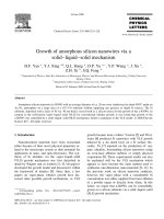
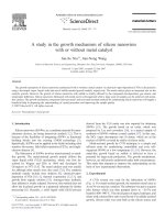
Fig. 1. (a–c) Room-temperature constant-current topographs of a HOPG surface area at more than 1 ML coverage with silicon
clusters. Image size: (a) 1.1×1.1 mm2,(b)44×44 nm2,(c)10×10 nm2; tunneling parameters: (a) U=1.0 V, I
t
=0.32 nA; (b, c) U=
2.5 V, I
t
=0.46 nA. (d ) Line-scan along the white line indicated in (c). (e) Size distribution of the silicon nanoclusters determined
from the STM images (a–c).
115P. Scheier et al. / Surface Science 458 (2000) 113–122
(equipped with heating and cooling facilities) 5 cm contrast to Ref. [30], the amount of silicon depos-
ited in the presently shown examples was muchin front of the sputter source. A manually operated
shutter was placed between the sputter source and smaller since both the opening of the shutter and
the argon ion current were reduced (<45 s insteadthe substrate holder during precleaning of the Si
target and served to control the Si arrival fluences. of 2 min and 50 mA instead of 200 mA). After
deposition, the sample was transferred in situ intoThe average size of the Si clusters synthesized by
this technique could be varied by changing the the STM chamber in order to characterize the
deposited silicon nanostructures under stringentsputter parameters, increasing (or decreasing) the
source-to-substrate distance, or a combination of ultra-high-vacuum ( UHV ) conditions. All STM
topographs presented in this work were taken withall these parameters [30]. In the present experi-
ments, typical exposure times were varied from a Pt/Ir tips on the same sample and were recorded
in constant current mode. The bias voltage betweenfew seconds to about a minute, yielding isolated
clusters or cluster films with a thickness of 1– tip and sample is taken with respect to the latter.
Tunneling resistances in the range between 100 MV3 ML (monolayers) on HOPG, respectively. In
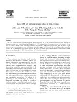
Fig. 2. (a–c) Room-temperature constant-current topographs of a HOPG surface area at about 0.1 ML coverage with silicon clusters.
Image size: (a) 400 × 400 nm2,(b)94× 94 nm2,(c)41× 41 nm2; tunneling parameters, (a–c) U=1.96 V, I
t
=0.32 nA. (d ) Section
of the HOPG hexagonal surface lattice showing the angle between armchair and zigzag directions.
116 P. Scheier et al. / Surface Science 458 (2000) 113–122
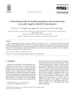
Fig. 3. (a–g) Room-temperature constant-current topographs of a HOPG surface area with nanopits of various depth at about 0.5 ML
coverage with silicon clusters. Image size: (a) 350×350 nm2, (b) 150×150 nm2, (c) 100×100 nm2;(d)20×20 nm2; (e) 86×86 nm2;
(f ) 100×100 nm2;(g)40×40 nm2; tunneling parameters: (a) U=−1.5 V, I
t
=0.38 nA; (b) U=1.1 V, I
t
=4.2 nA; (c) U=−1.3 V,
I
t
=0.38 nA; (d ) U=−1.4 V, I
t
=0.38 nA; (c) U=1.6 V, I
t
=0.26 nA; (c) U=0.73 V, I
t
=0.51 nA; (c) U=1.2 V, I
t
=0.51 nA. (h)
Constant-current topograph of a small island in the center of (f ) showing the graphite surface lattice with atomic resolution. Image
size: 3×3nm2; tunneling parameters: U=1.2 V, I
t
=0.68 nA.
and 6 GV yield identical images. Very similar ters. Two step edges of the HOPG substrate are
clearly visible in the image due to the denseimages have been obtained from other samples
prepared under the same experimental conditions. decoration with a chain of clusters. Fig. 1b and 1c
show a 44×44 nm2 and a 10×10 nm2 area, taken
across the left step in the bottom of Fig. 1a. These
images reveal round Si-structures in the size range3. Results
from 1 to several nanometers. A cross section,
indicated by a white line in Fig. 1c and shown inFig. 1a shows a 1.1×1.1 mm2 area of an HOPG
surface covered with about 3 ML of silicon clus- Fig. 1d reveals that the smallest round structures
117P. Scheier et al. / Surface Science 458 (2000) 113–122
Fig. 3. (continued)
are semi-spherical with a diameter (FWHM ) of thermal evaporation in an Ar buffer gas and
collected on HOPG, where the gathering of the Siabout 1 nm. Due to the convolution of tip and
object geometries the clusters appear larger as in nanoclusters at step edges as well as their self-
assembly into superclusters has been noted [31].reality. To correct for this effect we evaluated the
tip dimensions on the widths of monatomic steps Fig. 2a shows an STM topograph of a
400×400 nm2 area of HOPG taken at a lateralof pure HOPG yielding a tip contribution of
0.3 nm. Fig. 1f shows the corrected size distribu- distance of several micrometers from the region
shown in Fig. 1. Three step edges cross the imagetion of about 1000 Si-clusters obtained from an
analysis of Fig. 1a -e. It follows that all observed from the bottom to the top. The two uppermost
layers of graphite are partially folded back onnanostructures fall into three relatively narrow size
ranges. The smallest structures have an average their left-hand side, a phenomenon already well
known from earlier STM studies of HOPG [32,33].diameter of 0.6±0.2 nm, containing up to 10 Si
atoms [3–13,29]. Larger aggregates exhibit diame- In contrast to the observations made in Fig. 1, the
silicon coverage at this new position with a higherters of 5.1±1.2 nm, and the largest superclusters
have sizes in the range of 15.4±3 nm. This obser- density of defects is significantly smaller (about
0.1 ML), and the step edges are less densely decor-vation suggests that the small clusters of 1 nm
diameter constitute building blocks for the larger ated, although the flux of silicon atoms is expected
to be homogeneous over much larger surface areas.aggregates. These findings confirm similar observa-
tions made in a recent atomic force microscopy In the lower part of the uppermost terrace, an
elongated Si structure is visible. A close-up of a(AFM) study of Si nanocrystals synthesized by
118 P. Scheier et al. / Surface Science 458 (2000) 113–122
94×94 nm2 area of this region reveals a chain of the Si-step decoration of the upper step edge (see
Fig. 3c).
silicon clusters at an angle of 41.3° with respect to
We summarize our main experimental observa-
the step edge. A combination of armchair and
tions on the growth of Si nanostructures on HOPG
zigzag directions in the 2D-graphite hexagonal
as follows. The average silicon coverage varies by
network yields an angle close to this value, as
a factor of more than 10 between the surface
illustrated in Fig. 2d. We conclude that the
regions of different defect densities, separated by
arrangement of the carbon surface atoms in this
only 0.1 mm. The diameter of the clusters formed
crystallographic direction provides favorable bind-
onto defect-poor, flat surface regions is about
ing sites for such a chain-like structure. An closer
0.6 nm, while clusters attached to step edges or
look at this structure (Fig. 2c) reveals that the
defects have diameters of about 2 nm and, occa-
segments of this cluster chain have an average
sionally, are found to be fused into rod- or tubelike
thickness of 3.1±0.3 nm (see line scan) with
structures. In the coverage range between 0.5 and
lengths varying from 2.3 to 7.5 nm (uncorrected
5 ML, these small clusters often form superclusters.
values). In addition, on the two terraces shown in
The density and size of the clusters attached to the
Fig. 2b and c, uniformly sized (1.1±0.1 nm) Si
step edges forming HOPG nanopits are indepen-
clusters are distributed randomly. Most of these
dent of the width of their ‘feeding’ terraces. The
small silicon clusters form distinct, loosely packed
rims of nano-sized graphite islands on HOPG are
groups (only 10% of the small clusters have no
practically free of silicon decoration.
neighbors).
Fig. 3a–f shows constant current images of sur-
face areas containing craters and pits [34] with
4. Simulation
depth down to 10 ML. Every step edge of the
descending terraces is decorated with a chain of
In order to rationalize the above observations,
silicon clusters. The average diameter of all cluster
we simulate the growth process, i.e. adsorption,
chains in this area is 3.1±1.1 nm (see Fig. 2c, line
surface diffusion, and clustering of the silicon
scan) and thus seem not to depend on the width
atoms on HOPG within a simple two-dimensional
of the terraces limited by the steps. This value
model, as sketched in the flow diagram shown
corresponds well with the average diameter of the
in Fig. 4.
cluster chain observed in Fig. 2. Almost no silicon
In a first step, the topography of the surface is
clusters are found on the flat terraces. Only in the
defined. Within a two-dimensional array of
upper left-hand corner of Fig. 3a is the density of
400×400 pixels, the location of a step or defect is
the silicon clusters large enough to cover more
assigned a value of 1 (black pixel ), and all other
than just the steps. Images taken of adjacent
positions are set to zero (white pixel ). Fig. 5a
surface regions in this direction exhibit structures
displays a typical example of such a model surface
that are identical to those found in Fig. 1.
corresponding closely with the experimental STM
In Fig. 3b, c, f, and g, flat islands with diameters
image shown in Fig. 3a. The number, n, of indivi-
between 5 and 20 nm are visible on the larger
dual Si atoms adsorbed on the surface is chosen.
terraces. A high-resolution image of one of these
Furthermore, the number of diffusion jumps of a
islands is shown in Fig. 3h. A periodic lattice
single atom before desorption is considered (max-
identical to that of graphite is observed, which
steps), representing the residence time at the
allows us to identify these small islands as genuine
surface.
graphite nanoflakes. We note that we were able to
All adsorbed atoms move randomly along the
obtain this pattern only on very few HOPG flakes,
surface. Whenever an atom desorbs or attaches to
indicating a shift and/or rotation of these flakes
a nucleation site, such as a cluster or defect, it is
with respect to the underlying graphite layers.
replaced by a new one. In case of attachment, the
Finally, we note that in the STM images shown
number of Si atoms at the nucleation site is
increased by one. Collision with another adsorbedin Figs. 1–3, the respective line scans clearly reveal
119P. Scheier et al. / Surface Science 458 (2000) 113–122
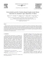
Fig. 4. Flow diagram of a two-dimensional growth simulation. n is the number of single atoms that are attached to the surface at all
times. If an atom desorbs, diffuses out of the defined surface area or fuses to a cluster or defect, it is replaced by a new incoming
atom. n is proportional to the flux of impinging atoms. maxsteps is the number of diffusion steps that a single atom can perform
before it desorbs from the surface.
atom leads to the formation of the smallest cluster, f displays simulated growth patterns for a surface
exhibiting the characteristic topography of Fig. 3a.a dimer. The probability for the desorption and
the diffusion of clusters is set to zero. Therefore, The total number of adsorbed atoms that form
clusters and decorations of defects is one milliononce a cluster is formed on a terrace, its migration
to a defect is excluded, and a new nucleation site for all four simulations. An atom density of n=2
atoms was used in the case of images Fig. 5c andis created. Fig. 5b shows the number of atoms
attached to each pixel of a surface area exhibiting d and n=1000 atoms for images Fig. 5e and f. In
Fig. 5c and e, the residence time was short (max-five step edges in terms of a bar diagram. The
height of each column represents the number of steps=1) whereas in Fig. 5d and f, an infinite
residence time was assumed (maxsteps=2). Foratoms at this location at the end of a simulation.
For a direct comparison of the simulated results the low atom density, clusters are formed almost
exclusively along the steps and defects (Fig. 5c andwith the STM images, semi-spherical clusters were
plotted where the cube of the radius is proportional d). In contrast, at high atom density, clusters are
also formed on the terraces (Fig. 5e and f ). Atto the number of atoms within the cluster. Fig. 5c–
120 P. Scheier et al. / Surface Science 458 (2000) 113–122
Fig. 5. Simulation of the Si-cluster growth (see text). (a) Model surface with defects (black lines). (b) Bar diagram of the number of
accumulated atoms at a few step edges. (c, d) Growth pattern after low-Si-atom density deposition at short (c) and long (d) residence
times of the Si-atoms at the surface. (e, f ) Growth pattern after high-Si-atom density deposition at short (e) and long (f ) residence
times. Note the excellent agreement of the results of these simulations with the observed growth patterns shown in Fig. 3.
121P. Scheier et al. / Surface Science 458 (2000) 113–122
short residence times, clusters are very uniform in flakes has a cluster attached to its edge. We attri-
bute this observation to two effects:size ( Fig. 5c and d ), whereas for an infinite resi-
dence time, their size depends strongly on the size 1. A vanishing Schwoebel–Ehrlich barrier on the
step edge of these very small HOPG islandsof the feeding terrace.
allowing for interlayer diffusion. At a critical
island size, such an effect has been invoked to
be responsible for ‘landsliding’ on small Cu
5. Discussion
islands [36,37].
2. Bond weakening of the HOPG nanoflakes
A comparison of the experimental STM image
towards the adsorbed Si atoms due to weak
of Fig. 3a with the results of the simulation dis-
coupling of these flakes to the underlying graph-
played in Fig. 5 clearly suggests that our simulation
ite surface. In the case of Pt on HOPG, the
captures the essential physics of the growth pro-
perfect stacking of the graphite layers has been
cess. After adsorption of single silicon atoms on
shown to be important for optimal bonding
the HOPG surface, these adatoms move randomly
[38,39].
by thermal diffusion along the surface. Collisions
among them lead to the growth of Si clusters. Step
edges with unsaturated or dangling bonds consti-
6. Summary and conclusions
tute preferred nucleation sites and exhibit an effec-
tive Schwoebel–Ehrlich [35] barrier for interlayer
Silicon nanoparticles were synthesized using
diffusion of Si adatoms. On surface regions with
magnetron sputtering deposition onto cleaved
an increased defect density, we observe a much
HOPG. The resulting Si nanostructures were inves-
smaller coverage of silicon (see Figs. 2 and 3:
tigated with STM. On defect-poor, flat regions of
0.1 ML) than on surface regions with a low defect
the HOPG surface, Si clusters with a mean diame-
density (see Fig. 1: 3 ML). For the simulation
ter of about 0.6 nm and a narrow size distribution
shown in Fig. 5c (which gives the best agreement
were found. On defect-rich surface regions, step
with the STM topograph), the residence time of
edge decoration was observed almost exclusively,
the adatoms was short. In other words, most of
while the terraces were free of attached particles.
the diffusing Si atoms desorb from the surface
A simple two-dimensional simulation of the Si
before they encounter a defect or collide with
cluster growth successfully describes most of the
another Si atom and form a cluster on a terrace.
experimental observations, e.g. the gathering of
For Fig. 5c, the second parameter used in the
clusters on step edges and the formation of clusters
simulation (the density of silicon atoms) was low.
and superclusters on the terraces. The simulation
This parameter can be interpreted as a combina-
leads to the conclusion that the sticking coefficient
tion of the flux from the sputter source and the
of the HOPG surface depends on the density of
sticking coefficient. In order to end up with the
the defects. The STM topographs reveal that the
same number of 1 million silicon atoms attached
silicon coverage on a defect-rich surface region is
to the surface (either in the form of clusters on
smaller by a factor of ~30 than on a defect-poor
terraces or decorations of edges and defects), the
region of the same sample. In view of the present
actual number of initial silicon atoms that hit our
results, magnetron sputtering might provide an
model surface was, in the case of Fig. 5c, about
interesting alternative route towards the pro-
100 times larger than for Fig 5f. This agrees very
duction of Si nanostructures with potential appli-
well with the experimental observation that a
cations in future silicon nanotechnology.
defect-poor region has about 30 times more silicon
attached than the defect-rich region of the same
sample.
Acknowledgements
The areas that exhibit pits and craters also
contain small HOPG islands or flakes that are
practically free of adsorbed silicon particles. For P.S. gratefully acknowledges an APART grant
from the Austrian Academy of Sciences, andexample, Fig. 3c reveals that only one out of 20
122 P. Scheier et al. / Surface Science 458 (2000) 113–122
[20] W.L. Wilson, P.F. Szajowski, L.E. Brus, Science 262
W.D.S. thanks the Swiss National Science
(1993) 1242.
Foundation for financial support.
[21] C. Delerue, M. Lannoo, G. Allan, E. Martin, I. Mihal-
cescu, J.C. Vial, R. Romestain, F. Muller, A. Bsiesy, Phys.
Rev. Lett. 75 (1995) 2228.
[22] A.A. Shvartsburg, M.F. Jarrold, B. Liu, Z Y. Lu, C Z.
Wang, K M. Ho, Phys. Rev. Lett. 81 (1998) 4616.
[23] Y. Kuk, M.F. Jarrold, P.J. Silverman, J.E. Bower, W.L.
References
Brown, Phys. Rev. B 39 (1989) 11168.
[24] J.M. Alford, R.T. Laaksonen, R.E. Smalley, J. Chem.
[1] Cluster Assembled Materials, K. Sattler (Ed.), Materials
Phys. 94 (1996) 2618.
Science Forum Vol. 232 Trans. Tech. Publ, Switzerland,
[25] M.F. Jarrold, V.A. Constant, Phys. Rev. Lett. 67 (1991)
1996.
2994.
[2] M.A. Duncan, D.H. Rouvray, Sci. Am. 261 (1989) 110
[26 ] D.W. McComb, B.A. Collings, R.A. Wolkow, D.J. Moffat,
December.
C.D. Mac Pherson, D.M. Rayner, P.A. Hackett, J.E.
Hulse, Chem. Phys. Lett. 251 (1996) 8.[3] A.P. Alivisatos, Science 271 (1996) 933.
[27] L.N. Dinh, L.L. Chase, M. Balooch, L.J. Terminello, F.
[4] J. Shi, S. Gider, K. Babcock, D.D. Awschalom, Science
Wooten, Appl. Phys. Lett. 65 (1994) 3111.
271 (1996) 937.
[28] L.N. Dinh, L.L. Chase, M. Balooch, W. Siekhaus, F.
[5] E. Kaxiras, Phys. Rev. Lett. 64 (1990) 551.
Wooten, Phys. Rev. B 54 (1996) 5029.
[6] W. Andreoni, G. Pastore, Phys. Rev. B 41 (1990) 10243.
[29] S. Messerli, S. Schintke, K. Morgenstern, A. Sanchez, U.
[7] C.H. Patterson, R.P. Messmer, Phys. Rev. B 42 (1990)
Heiz, W D. Schneider, Surf. Sci. (2000) in press.
7530.
[30] B. Marsen, K. Sattler, Phys. Rev. B 60 (1999) 11593.
[8] J.R. Chelikowsky, K.M. Glassford, J.C. Phillips, Phys.
[31] T. van Buuren, L.N. Dinh, L.L. Chase, W.J. Siekhaus,
Rev. B 44 (1991) 1538.
L.J. Terminello, Phys. Rev. Lett. 80 (1998) 3803.
[9] E. Kaxiras, K. Jackson, Phys. Rev. Lett. 71 ( 1993) 727.
[32] H V. Roy, C. Kallinger, K. Sattler, Surf. Sci. 407 (1998) 1.
[10] U. Ro
¨
thlisberger, W. Andreoni, M. Parrinello, Phys. Rev.
[33] H V. Roy, C. Kallinger, B. Marsen, K. Sattler, J. Appl.
Lett. 72 (1994) 665.
Phys. 83 (1998) 4659.
[11] J.C. Grossman, L. Mita´s, Phys. Rev. Lett. 74 (1995) 1323.
[34] G. Bra
¨
uchle, S. Richard-Schneider, D. Illig, R.D. Beck, H.
[12] M. Menon, E. Richter, Phys. Rev. Lett. 83 (1999) 792.
Schreiber, M.M. Kappes, Nucl. Instrum. Meth. Phys. Res.
[13] J. Pan, M.V. Ramakrishna, Phys. Rev. B 50 (1994) 15431.
B 112 (1996) 105.
[14] R.E. Honig, J. Chem. Phys. 22 (1954) 1610.
[35] K. Morgenstern, G. Rosenfeld, E. Lægsgaard, F. Besen-
[15] T.T. Tsong, Appl. Phys. Lett. 45 (1984) 1149.
bacher, G. Comsa, Phys. Rev. Lett. 80 (1998) 556 and
[16] L.A. Bloomfield, R.R. Freeman, W.L. Brown, Phys. Rev.
references therein.
Lett. 54 (1985) 2246.
[36 ] M. Giesen, G. Schulze Icking-Konert, H. Ibach, Phys. Rev.
[17] W.L. Brown, R.R. Freeman, K. Raghavachari, M.
Lett. 80 (1998) 552.
Schlu
¨
ter, Science 235 (1987) 860.
[37] M. Giesen, G. Schulze Icking-Konert, H. Ibach, Phys. Rev.
[18] M.F. Jarrold, Science 252 (1991) 1085.
Lett. 82 (1999) 3101.
[19] E.C. Honea, A. Ogura, C.A. Murray, K. Raghavachari,
[38] U. Mu
¨
ller, K. Sattler, J. Xhie, N. Venkateswaran, G.
W.O. Sprenger, M.F. Jarrold, W.L. Brown, Nature 366
Raina, Z. Phys. D 19 (1991) 319.
[39] J. Xhie, K. Sattler, M. Ge, Phys. Rev. B 47 (1993) 15835.(1993) 42.