Security Analysis of a Cryptographically-Enabled RFID Device ppt
Bạn đang xem bản rút gọn của tài liệu. Xem và tải ngay bản đầy đủ của tài liệu tại đây (522.83 KB, 15 trang )
Security Analysis of a Cryptographically-Enabled
RFID Device
Stephen C. Bono
∗
Matthew Green
∗
Adam Stubblefield
∗
Ari Juels
†
Aviel D. Rubin
∗
Michael Szydlo
†
Abstract
We describe our success in defeating the security of an
RFID device known as a Digital Signature Transponder
(DST). Manufactured by Texas Instruments, DST (and
variant) devices help secure millions of SpeedPass
TM
payment transponders and automobile ignition keys.
Our analysis of the DST involved three phases:
1. Reverse engineering: Starting from a rough pub-
lished schematic, we determined the complete
functional details of the cipher underpinning the
challenge-response protocol in the DST. We accom-
plished this with only “oracle” or “black-box” ac-
cess to an ordinary DST, that is, by experimental
observation of responses output by the device.
2. Key cracking: The key length for the DST is only
40 bits. With an array of of sixteen FPGAs operat-
ing in parallel, we can recover a DST key in under
an hour using two responses to arbitrary challenges.
3. Simulation: Given the key (and serial number) of
a DST, we are able to simulate its RF output so as
to spoof a reader. As validation of our results, we
purchased gasoline at a service station and started
an automobile using simulated DST devices.
We accomplished all of these steps using inexpensive
off-the-shelf equipment, and with minimal RF expertise.
This suggests that an attacker with modest resources can
emulate a target DST after brief short-range scanning or
long-range eavesdropping across several authentication
sessions. We conclude that the cryptographic protection
afforded by the DST device is relatively weak.
Key words: Digital Signature Transponder (DST),
immobilizer, Hellman time-space tradeoff, RFID
∗
Department of Computer Science; The Johns Hopkins Univer-
sity; 3400 N. Charles Street; Baltimore, MD 21218, USA. Email:
{sbono,mgreen,astubble,rubin}@cs.jhu.edu.
†
RSA Laboratories, 174 Middlesex Turnpike, MA 01739, USA.
Email: {ajuels,mszydlo}@rsasecurity.com.
1 Introduction
Radio-Frequency IDentification (RFID) is a general term
for small, wireless devices that emit unique identifiers
upon interrogation by RFID readers. Ambitious deploy-
ment plans by Wal-mart and other large organizations
over the next couple of years have prompted intense com-
mercial and scientific interest in RFID [23]. The form
of RFID device likely to see the broadest use, particu-
larly in commercial supply chains, is known as an EPC
(Electronic Product Code) tag. This is the RFID device
specified in the Class 1 Generation 2 standard recently
ratified by a major industry consortium known as EPC-
global [9, 19]. EPC tags are designed to be very inex-
pensive – and may soon be available for as little as five
cents/unit in large quantities according to some projec-
tions [21, 20]. They are sometimes viewed in effect as
wireless barcodes: They aim to provide identification,
but not digital authentication. Indeed, a basic EPC tag
lacks sufficient circuitry to implement even symmetric-
key cryp tographic primitives [21].
The term RFID, however, denotes not just EPC tags,
but a spectrum of wireless devices of varying capabil-
ities. More sophisticated and expensive RFID devices
can offer cryptographic functionality and therefore sup-
port authentication protocols. One of the most popular of
such devices is known as a Digital Signature Transpon-
der (DST). Manufactured by Texas Instruments, DSTs
are deployed in several applications that are notable for
wide-scale deployment and the high costs (financial and
otherwise) of a large-scale security breach. These in-
clude:
• Vehicle Immobilizers: More than 150 million ve-
hicle immobilizer keys shipped with many cur-
rent automobiles, including e.g. 2005 model
Fords [7], use Texas Instruments low-frequency
RFID transponders. This number includes sys-
tems with fixed-code transponders that provide no
cryptographic security, as well as newer models
14th USENIX Security Symposium
USENIX Association
1
14th USENIX Security Symposium
equipped
with DSTs. Immobilizers deter vehicle
theft by interrogating an RFID transponder embed-
ded in the ignition key as a condition of enabling
the fuel-injection system of the vehicle. The de-
vices have been credited with significant reductions
in auto theft rates, as much as 90% [1, 8].
• Electronic Payment: DSTs are used in the Exxon-
Mobil SpeedPass
TM
system, with more than seven
million cryptographically-enabled keychain tags ac-
cepted at 10,000 locations worldwide [2].
A DST consists of a small microchip and antenna coil
encapsulated in a plastic or glass capsule. It is a passive
device, which is to say that it does not contain an on-
board source of power, but rather receives its power via
electromagnetic inductance from the interrogation signal
transmitted by the reading device. This design choice
allows for a compact design and long transponder life.
A DST contains a secret, 40-bit cryptographic key that
is field-programmable via RF command. In its interac-
tion with a reader, a DST emits a factory-set (24-bit)
identifier, and then authenticates itself by engaging in
a challenge-response protocol. The reader initiates the
protocol by transmitting a 40-bit challenge. The DST
encrypts this challenge under its key and, truncating the
resulting ciphertext, returns a 24-bit response. It is thus
the secrecy of the key that ultimately protects the DST
against cloning and simulation.
In this paper, we describe our success in attacking the
Texas Instruments DST system. We are able to recover
the secret cryptographic key from a target DST device
after harvesting just two challenge-response pairs. For
arbitrary challenge-response pairs, we are able to recover
a key in under an hour using an array of sixteen FP-
GAs. When the challenge-response pairs derive from
pre-determined challenges, i.e., in a chosen-plaintext at-
tack, a time-space trade-off is possible, reducing the
cracking time to a matter of minutes. The full details of
this chosen-response attack will appear in a future ver-
sion of this work. Once we have recovered a key, we
are able to use an inexpensive, commodity RF device to
“clone” the target DST, that is, to simulate its radio out-
put so as to convince a reader.
In consequence, we show how an attacker with mod-
est resources — just a few hundred dollars worth of com-
modity equipment and a PC — can defeat the DST sys-
tem. Such an attacker can succeed upon actively skim-
ming a DST, that is, scanning it at short range for a frac-
tion of a second. With additional use of an FPGA, an
attacker can feasibly simulate a target DST after merely
intercepting multiple authentication transcripts at longer
range.
To validate our attack, we extracted the key from our
own SpeedPass
TM
token and simulated it in an indepen-
dent programmable RF device. We purchased gasoline
successfully at an ExxonMobil station multiple times in
the course of a single day using this digital simulator.
Similarly, we recovered the cryptographic key from a
DST in the ignition key of our 2005 model Ford Escape
SUV. By simulating the DST, we spoofed the immobi-
lizer authentication system and started the vehicle with a
bare ignition key, that is, a copy of the metal portion of
the key that possessed no DST. Viewed another way, we
created the pre-conditions for hot-wiring the vehicle.
Our aim in demonstrating the vulnerability of the TI
DST is twofold. First, we wish to reinforce the time-
worn but oft neglected message that “security through
obscurity” is generally ineffective in widely fielded cryp-
tographic systems. Second, we wish to provide guidance
to the data-security community in ascertaining the design
requirements for secure RFID systems.
Our attack involved three phases:
1. Reverse engineering: We obtained a rough pub-
lished schematic of the block cipher underpinning
the challenge-response protocol in the DST [14].
From this starting point, we determined the com-
plete functional details of the cipher. We accom-
plished this with only “oracle” or “black-box” ac-
cess to an ordinary DST, that is, by experimental
observation of responses output by the device across
selected programmed encryption keys and selected
input challenges. This phase of the attack was the
scientific heart of our endeavor, and involved the
development of cryptanalytic techniques designed
specially for the DST cipher.
2. Key cracking: As mentioned above, the key length
for the DST is only 40 bits. We assembled an ar-
ray of sixteen FPGAs operating in parallel. With
this system, we can recover a DST key in un-
der an hour from two responses to arbitrary chal-
lenges. Additionally, we have constructed an FPGA
for computing the well known time-space tradeoff
of Hellman [12]. Although we pre-compute the
underlying look-up tables using the FPGA (Field-
Programmable Gate Array), we estimate that the re-
sulting software will operate on an ordinary, unen-
hanced PC in under a minute. (With the aid of an
FPGA at this stage, the cracking time can be re-
duced to seconds.) A full analysis of this system
will appear in a future version of this work.
3. Simulation: Given the key (and serial number) of
a DST, we are able to simulate its RF output so as
to spoof a reader. We perform the simulation in a
software radio. Construction of this system required
careful analysis of the RF output of the DST reader
devices, which differed between SpeedPass
TM
read-
USENIX Association
2
ers and the automobile ignition system we exam-
ined.
1.1 Related work
The pre-eminent historical example of black-box
reverse-engineering of a cipher was the reconstruction
of the Japanese Foreign Office cipher Purple during the
Second World War. Under the leadership of William F.
Friedman, the United States Signals Intelligence Service
performed the feat of duplicating the Purple enciphering
machine without ever having physical access to one [13].
There are a number of well known contemporary ex-
amples of the reverse-engineering of proprietary crypto-
graphic algorithms. For example, the RC4 cipher, for-
merly protected as a trade secret by RSA Data Security
Inc., was publicly leaked in 1994 as the result of what
was believed to be reverse-engineering of software im-
plementations [4]. The A5/1 and A5/2 ciphers, employed
for confidentiality in GSM phones, were likewise pub-
licly disclosed as a result of reverse engineering. The
exact method of reverse-engineering has not been dis-
closed, although the source was purportedly “an actual
GSM phone” [6].
There are also numerous published fault-induction and
side-channel attacks against hardware devices, e.g., [5].
These are related to our work, but involve rather different
techniques, and generally aim to recover a key, rather
than a cipher design.
In fact, we are unaware of any published black-box
reverse-engineering of a contemporary cipher, whether
the original source be a software or a hardware imple-
mentation. Having no literature to refer to, we developed
techniques for our effort in an ad hoc manner. While
our techniques are not easily generalizable, we hope that
they will nonetheless aid future researchers at a concep-
tual level in similar endeavors.
In contrast, the key-recovery techniques we employed
are well known. Our parallel FPGA key-recovery sys-
tem operates on much the same principle, for example,
as the well publicized Deep Crack machine that em-
ployed hardware-based key-space searching to recover
DES keys [10, 17].
As mentioned above, our system for key recovery in
software using chosen-challenge pairs exploits the time-
space tradeoff developed by Hellman. We also employ
the “distinguished point” enhancement of Rivest. We
have drawn on previous work by Quisquater et al. [18],
who created a Hellman-based system for recovering keys
from a variant of DES employing 40-bit keys.
We note that we have chosen in this document to re-
veal information about the DST cipher sufficient to elu-
cidate our reverse-engineering and analysis techniques.
We omit details about that would permit direct recon-
struction of the cipher. Our goal is to offer our fullest
possible
contribution to the scientific community, but at
the same time to avoid fomenting abuse of our results.
Once the industry has had time to take adequate mea-
sures, we intend to divulge full cipher details in the inter-
est of stimulating cryptanalytic research by the scientific
community.
In general, the problem of achieving authentication in
RFID devices – with and without full-blown cryptogra-
phy – has seen a recent burgeoning in the data-security
literature. An up-to-date bibliography may be found at
[3].
Organization
In section 2, we discuss the practical implications of our
simulation attack against the DST. We then detail the
three phases of our attack. In section 3, we discuss the
techniques we employed in reverse-engineering the DST
cipher. We describe our key-cracking system in sec-
tion 4. In section 5, we recount the experimentation and
analysis we performed to understand the DST protocol
at the RF layer, as well as our simulation techniques. We
conclude in section 6.
2 Practical Significance of Our Results
Our attack on the DST cipher by no means im-
plies wholesale dismantling of the security of the
SpeedPass
TM
network, nor easy theft of automobiles.
The cryptographic challenge-response protocols of DST
devices constitute only one of several layers of secu-
rity in these systems. ExxonMobil informed us that the
SpeedPass
TM
network has on-line fraud detection mech-
anisms loosely analogous to those employed for tradi-
tional credit-card transaction processing. Thus an at-
tacker that simulates a target DST cannot do so with
complete impunity; suspicious usage patterns may re-
sult in flagging and disabling of a SpeedPass
TM
device
in the network. The most serious system-wide threat lies
in the ability of an attacker to target and simulate multi-
ple DSTs, as suggested in our example scenarios below.
In some sense, the threat to automobile immobiliz-
ers is more serious, as: (1) An automobile is effectively
an off-line security system and (2) A single successful
attack on an automobile immobilizer can result in full
compromise of the vehicle. While compromise of a DST
does not immediately permit theft of an automobile, it
renders an automobile with an immobilizer as vulnerable
to theft as an automobile without one. Such a rollback in
automobile security has serious implications. As noted
above, significant declines in automobile theft rates – up
to 90% – have been attributed to immobilizers during
their initial introduction. Even now, automobile theft is
14th USENIX Security Symposium
USENIX Association
3
14th USENIX Security Symposium
an enormous criminal industry, with 1,260,471 automo-
bile thefts registered by the FBI in 2003 in the United
States alone, for a total estimated loss of $8.6 billion
[16].
Extracting the key from a DST device requires the
harvesting of two challenge-response pairs. As a result,
there
are certain physical obstacles to successful attack.
Nonetheless, bypassing the cryptographic protections in
DST devices results in considerably elevated real-world
threats. In this section we elaborate on the context and
implications of our work.
2.1 Effective attack range
There are effectively two different methods by which an
attacker may harvest signals from a target DST, and two
different corresponding physical ranges.
The first mode of attack is active scanning: The at-
tacker brings her own reader within scanning range of
the target DST. DSTs of the type found in SpeedPass
TM
and automobile ignition keys are designed for short range
scanning – on the order of a few centimeters. In practice,
however, a longer range is achievable. In preliminary ex-
periments, we have achieved an effective range of several
inches for a DST on a keyring in the pocket of a simu-
lated victim. A DST may respond to as many as eight
queries per second. Thus, it is possible to perform the
two scans requisite for our simulation attacks in as lit-
tle as one-quarter of a second. At the limit of the range
achievable by a given antenna, however, scanning be-
comes somewhat unreliable, and can require more time.
From the standpoint of an attacker, active scanning
has the advantage of permitting a chosen-challenge at-
tack. Hence this type of attack permits the use of pre-
computed Hellman tables as touched on above. In prin-
ciple, therefore, it would be possible for an attacker with
appropriate engineering expertise to construct a com-
pletely self-contained cloning device about the size of
an Apple iPod. When passed in close proximity to a tar-
get DST, this device would harvest two chosen-challenge
transcripts, perform a lookup in an on-board set of pre-
computed Hellman tables in the course of a minute or so,
and then simulate the target DST. We estimate that the
cost of constructing such a device would be on the order
of several hundred dollars.
The second mode of attack is passive eavesdropping.
Limitations on the effective range of active scanning
stem from the requirement that a reader antenna furnish
power to the target DST. An attacker might instead eaves-
drop on the communication between a legitimate reader
and a target DST during a valid authentication session. In
this case, the attacker need not furnish power to the DST.
The effective eavesdropping range then depends solely
on the ability to intercept the signal emitted by the DST.
We have not performed any experiments to determine the
range at which this attack might be mounted. It is worth
noting purported U.S. Department of Homeland Secu-
r
ity reports, however, of successful eavesdropping of this
kind on 13.56 Mhz tags at a distance of some tens of
feet [24]. The DST, as we explain below, operates at
134 kHz. Signals at this considerably lower frequency
penetrate obstacles more effectively, which may facili-
tate eavesdropping. On the other hand, larger antennas
are required for effective signal interception.
Only careful experimentation will permit accurate as-
sessment of the degree of these two threats. Our cursory
experiments, however, suggest that the threats are well
within the realm of practical execution.
2.2 Example attack scenarios
For further clarification of the implications of our work,
we offer a few examples of possible DST exploits. We
let Eve represent the malefactor in these scenarios.
Example 1 (Auto theft via eavesdropping) Eve runs an
automobile theft ring. She owns a van with eavesdrop-
ping equipment. She parks this near a target automo-
bile so as to eavesdrop on ignition-key-to-reader trans-
missions.
1
After observing two turns of the ignition key,
she is able to extract the cryptographic key of the DST
at her leisure using an FPGA. She returns subsequently
to steal the target automobile. To enter the vehicle, she
picks or jimmies the door lock. She then hot-wires the
ignition and deactivates the immobilizer by simulating
the DST of the real key.
Example 2 (Auto theft via active attack) Eve runs an
automobile theft ring. She suborns a valet at an expen-
sive restaurant to scan the immobilizer keys of patrons
while parking their cars, and to note their registration
numbers. Based on these registration numbers, Eve looks
up the addresses of her victims (such background checks
being widely offered on the Internet). By simulating their
DST devices, Eve is able to steal their automobiles from
their homes.
Example 3 (SpeedPass
TM
theft via active attack) Eve
carries a reader and short-range antenna with her onto
a subway car. (Alternatively, Eve could carry a large
“package” with a concealed antenna in some public
place.) As she brushes up near other passengers, she
harvests chosen challenge-response pairs (along with the
serial numbers of target devices) from any SpeedPass
TM
tokens they may be carrying. Later, at her leisure, Eve re-
covers the associated cryptographic keys. She programs
the keys into a software radio, which she uses to purchase
gasoline. To allay suspicion, she takes care to simulate a
compromised SpeedPass
TM
only once. Additionally, she
hides the tag simulator itself under her clothing, interact-
ing with the pump reader via an antenna passing through
USENIX Association
4
a sleeve up to an inactive SpeedPass
TM
casing.
2.3 Fixes
The most straightforward architectural fix to the prob-
lems we describe here is simple: The underlying cryp-
tography should be based on a standard, publicly scru-
tinized algorithm with an adequate key length, e.g.,
the Advanced Encryption Standard (AES) in its 128-bit
form, or more appropriately for this application, HMAC-
SHA1 [15]. From a commercial standpoint, this ap-
proach may be problematic in two respects. First, the re-
quired circuitry would result in a substantially increased
manufacturing cost, and might have other impacts on the
overall system architecture due to increased power con-
sumption. Second, there is the problem of backwards
compatability. It would be expensive to replace all exist-
ing DST-based immobilizer keys. Indeed, given the long
production cycles for automobiles, it might be difficult to
introduce a new cipher into the immobilizers of a partic-
ular make of vehicle for a matter of years. On the other
hand, it may be presumed from the Kaiser presentation
[14] that Texas Instruments has plans to update their ci-
pher designs in the DST. Additionally, TI has indicated
to the authors that they have more secure RFID products
available at present; in lieu of specifying these products,
they have indicated the site www.ti-rfid.com for informa-
tion.
In fact, RFID chips with somewhat longer key-lengths
are already available in the marketplace and used in a
range of automobile immobilizers. Philips offers two
cryptographically enabled RFID chips for immobilizers
[8]. The Philips HITAG 2, however, has a 48-bit secret
key, and thus offers only marginally better resistance to
a brute-force attack – certainly not a comfortable level
for long-term security. The Philips SECT, in contrast,
has a 128-bit key. The HITAG 2 algorithm is propri-
etary, while Philips data sheets do not appear to offer
information about the cryptographic algorithm underpin-
ning their SECT device. Thus, at present, we cannot say
whether these algorithms are well designed.
Faraday shielding offers a short-term, partial remedy.
In particular, users may encase their DSTs in aluminum
foil or some suitable radio-reflective shielding when not
using them. This would defend against active scanning
attacks, but not against passive eavesdropping. More-
over, this approach is rather inconvenient, and would
probably prove an unworkable imposition on most users.
A different measure worth investigation is the placement
of metal shielding in the form of a partial cylinder around
the ignition-key slot in automobiles. This could have the
effect of attenuating the effective eavesdropping range.
In the long-term, the best approach is, of course, the
development of solid, well-modeled cryptographic pro-
tocols predicated on industry-standard algorithms, with
key lengths suitable for long-term hardware deployment.
3 Reverse Engineering
W
e now present the details of our attack.
The 40-bit cipher underpinning the DST system is pro-
prietary. We refer to this cipher, in accordance with the
Texas Instruments documentation, as DST40. The only
substantive technical information we were able to locate
on DST40 was a rough schematic available in a presenta-
tion by Dr. Ulrich Kaiser, which was published on the In-
ternet [14], and in a published conference paper [11] co-
authored by Dr. Kaiser with Texas Instruments employ-
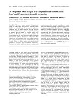
ees. We show the schematic here in Figure 1. Although
the general form and arrangement of functional compo-
nents of the cipher are clear, critical details about the
logic and interconnections of the components are lack-
ing. Moreover, as we shall explain, cer tain features in
the published schematic are inaccurate, in the sense that
they do not correspond to the workings of the fielded ver-
sions of DST40 we have examined. To distinguish over
the DST40 cipher employed in the implementations that
we experimented with, we refer to the cipher adumbrated
in Figure 1 as the Kaiser cipher.
We considered several initial approaches to reverse-
engineering DST40. Software packages available from
TI may include the DST40 cipher. These packages, how-
ever, include license agreements that prohibit reverse-
engineering, so we did not make use of them. We might
alternatively have attempted to probe a hardware imple-
mentation of DST-40. Lacking the resources for this ap-
proach and aiming, moreover, to explore the minimum
resource requirements to attack the DST system success-
fully, we rejected this option. Instead, we chose to mount
an “oracle” or “black-box” attack. This is to say that we
chose to uncover the functional details of DST40 simply
by examining the logical outputs of a DST device. As
the keys of some DST devices are field-programmable,
we were able to experiment with a set of chosen keys
and inputs for DST40. For our experiments, we pur-
chased a TI Series 2000 - LF RFID Evaluation Kit; this
kit co ntained a reader and antenna, as well as a variety of
non-DST RFID devices. We were able to separately pur-
chase small quantities of DST devices in two different
form factors.
To explain our effort further, some nomenclature is in
order. As the TI schematic of the Kaiser cipher suggests,
DST40 is essentially a feedback shift register. In each
round of operation, inputs from the challenge register
and key register pass through a collection of logical units.
These yield an output value that is fed back into the chal-
lenge register. We refer to the full collection of logical
units operating in a single round, i.e., operating on a sin-
14th USENIX Security Symposium
USENIX Association
5
14th USENIX Security Symposium
Digital S ignature T ransponder (3)
Digital S ignature T ransponder (3)
400 cloc ks 10 rounds
Dr. Ulrich K a iser T exas Ins truments D eutschland G mbH
Digital S ignature DS T40 Algorithm implementation
E
ncry ption K ey R egister
C
hall enge/R esponse R egister
R
outing
Network
R
outing
N
etwork
400/3clocks
f8f4f5f6f7f1f2f3 f16f12 f13 f14 f15f9 f10 f11
f
21
f
20
f19
f
18
f
17
Figure 1: Schematic of Kaiser Cipher.
gle set of inputs with no feedback, as F . The function F
comprises three logical layers.
The first layer, represented in the schematic by boxes
f
1
f
16
, consists of a collection of sixteen functional
units, each of which takes a small number of bits from
the key register and a small number of bits from the chal-
lenge register and yields a one-bit output. We refer to
these functional units as f-boxes. Each f-box takes ei-
ther three key bits and two challenge bits or vice versa;
two special f -boxes take only two bits from each register
as input.
The second layer, represented in the schematic by
boxes f
17
f
20
, consists of four functional units, each of
which takes as input the outputs of a set of four f-boxes.
We refer to each of these second-layer units as a g-box.
Finally, the third layer consists of a single functional
unit, labeled f
21
, into which feed the outputs of the g-
boxes. This last functional unit, which we refer to as the
h-box, yields the output of the full function F .
There are two main technical lacunae in the TI
schematic. Reverse-engineering DST40 required that we
focus on these. In particular:
1. The schematic does not describe the logical opera-
tions executed by the f -boxes, the g-boxes, and the
h-box.
2. The mapping of key and challenge bits to the f -
boxes is governed by a routing array whose organi-
zation the TI schematic does not describe. In other
words, there is no indication of which bits in the
challenge and key registers are input to which f -
boxes.
In addition, as we shall explain, the TI schematic con-
tains some inaccuracies, in the sense that the Kaiser ci-
pher does not correspond exactly to DST40 as imple-
mented in DST devices. Critically, the function F (and
thus the h-box) in DST40 actually outputs a pair of bits,
and the clocking of the cipher is accordingly different.
Moreover, two bits in the challenge register are XORed
with the output of the h-box.
3.1 Obtaining a single-round output
Because we did not know the contents of the f-boxes, or
other critical details such as the configuration of the rout-
ing networks in DST40, we could not directly verify that
production DSTs, such as those that we obtained for our
experiments, implemented the Kaiser cipher of Figure 1.
Instead we had to test and exploit structural features of
the Kaiser cipher, using our evaluation DST as an oracle.
We first noted that the only round dependence of the
Kaiser cipher is in the key scheduler. As seen in Figure 1,
a
→
0
key, i.e., string of ‘0’ bits, will remain unchanged in
USENIX Association
6
the key register throughout the cipher execution. Using
this key, it is possible to render each step of the algorithm
independent of the round in which it takes place. We
used the
→
0
key for the experimen ts we now describe.
We next observed that each cycle, i.e., each execu-
tion of F , results in only a small change to the state of
the challenge register: The contents of the register are
shifted right by one bit, and the output of the h-box is
inserted into the leftmost bit position. Consequently, for
any given value submitted to the tag, the challenge regis-
ter can assume only two possible values after one clock
cycle, depending on whether the h-box outputs a ‘0’ or a
‘1’ bit.
Using the DST as an oracle, we developed a test to
recover the output of the h-box for any value in the chal-
lenge/response register (which for brevity we henceforth
refer to as the challenge register). Consider a given chal-
lenge/response pair C, R. Upon input of C to the DST
device, the challenge register initially contains the bits of
C. Let C
denote the sequence of bits in C excluding the
last bit, i.e., the first 39 bits in C. Based on our observa-
tion above, after a single cycle, the challenge register in
the DST contains one of two possible sequences, either
C
0
=0| C
or C
1
=1| C
, where | denotes concatena-
tion. Therefore, recovering the output of the h-box can
be reduced to a determination of whether the challenge
register assumes the value C
0
or C
1
after the first cycle.
Fortunately, access to the DST as a challenge/response
oracle offers a simple way to make this determination. If
C
0
is truly the “next-state” value in the challenge register,
then application of the full encryption process, i.e., the
full 400 clock cycles on C
0
, will yield a result identical
to the encryption of C, but shifted one cycle ahead. The
original response R will therefore appear in the challenge
register exactly one clock cycle prior to the encryption
finishing. Thus, the final result, which we call R
0
, will
contain R, but shifted right by one bit. Alternatively, if
C
0
is not the next-state value of the challenge register,
the oracle will likely produce a response unrelated to the
original response R, as the single-bit difference will tend
to be amplified by the cipher over hundreds of rounds.
The analogous observation holds, of course, for C
1
.
Based on the assumption that the encryption circuitry
in a production DST tag implements the algorithm of
Figure 1, we performed this test using an evaluation
DST purchased from Texas Instruments. First, we pro-
grammed the DST with the
→
0
key, then submitted a chal-
lenge C, along with the two possible “next-state” values
C
0
and C
1
.
Unfortunately, this test failed to produce the results
we expected, indicating that DST40, the algorithm in the
production DST, differs from the Kaiser cipher. After
submitting a number of properly-formed challenges to
the DST, we saw none of the expected correlations – i.e.,
neither C
0
nor C
1
produced responses correlated to the
original response R.
Through trial and error, we discovered that the method
of testing next-state challenge-register values succeeded
w
hen we modeled the output of the h-box as two
bits. For a given challenge C, this required that
we instead compute four candidate next-state values,
C
00
,C
01
,C
10
,C
11
, i.e., one for each of the possible out-
put bit-pairs of the h-box. In our experiments, at least
one of these four candidates always produced a response
corresponding to the initial response R, but shifted right
by two bits.
2
One possible explanation was that the cir-
cuit alters its operation every other clock cycle, causing
our test to malfunction. It was far more likely, however,
that the production cipher DST40 simply produces two
bits per cycle. Such a divergence from the diagram of
Figure 1 called into question other elements of the dia-
gram, including the number of rounds in the encryption
process, and the key update schedule.
With the ability to recover the output of F on a single
cipher iteration, we were able to use our oracle to observe
each round of a cipher execution from start to finish, by
repeatedly guessing the next state of the challenge reg-
ister. This approach established that the encryption pro-
cess took place over 200 cycles, i.e., 200 executions of
F , and that the DST draws its response from the right-
most 24 bits of the challenge register on the conclusion
of this process.
3.2 Recovering the key schedule
Our experiments, as described above, relied on the as-
sumption that the
→
0
key remains constant through every
cycle of the encryption process. Using only the
→
0
key,
however, would restrict our ability to experiment with
the algorithm internals. We required the ability to ob-
serve single-round outputs based on different values in
the challenge and key registers.
Using a non-zero key again made the algorithm round-
dependent, with the result that our previous tests would
no longer produce useful results. In order for our “next-
state” candidate challenges to be encrypted properly, we
needed to provide the oracle with the equivalent next-
state of the key register.
Our next step, therefore, was to reverse-engineer the
key schedule. Following the diagram, we assumed that
new key bits were computed every few cycles by the
exclusive-or of several bits of the key. By querying
our oracle, we determined that the key is updated ev-
ery three cycles, beginning with the second cycle – not
the first, as suggested by the Kaiser diagram. We also
determined that while four bits are indeed exclusive-
ored together, they are not the bits shown in the dia-
14th USENIX Security Symposium
USENIX Association
7
14th USENIX Security Symposium
gram. Let k
i
denote the i
th
bit in the key register, be-
ginning with 0. The actual key update is defined by
k
0
= k
39
⊕ k
37
⊕ k
20
⊕ k
18
. Note that this design rep-
resents an LFSR with a primitive-characteristic polyno-
mial, so all keys other than the
→
0
key produce maximal
length sequences of key register values. Using this model
for the key schedule in place of the
→
0
key, we were able
to simulate steps of the algorithm for any key.
With the
→
0
key, we only had to guess each of the pos-
sibilities for the 2-bit output of a single round. To ex-
periment with a non-zero key k, we needed to guess six
successive bits (three bit-pairs) of output for the h-box
simultaneously, because the key schedule only repeats
every three cycles. (6 is the l .c.d. of 2 and 3.) This
meant testing 64 possible candidate challenge-register
states, {C
b
1
b
2
b
3
b
4
b
5
b
6
}
b
1
,b
2
, ,b
6
∈{0,1}
. To test one of
these challenge-register states, we programmed into the
DST device a key k
corresponding to the key-register
state after six cipher cycles applied to k. A DST can
process 6-8 challenges per second, so this test requires a
minimum of 8 seconds or so. It is thus significantly more
time-consuming than previous tests, although it returns
the output of three execution cycles, rather than one.
3.3 Uncovering the Feistel structure of
DST40
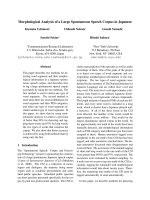
Figure 2 shows the probability that modifying an indi-
vidual challenge bit results in a change to the output of
F . To measure this effect, we generated a random key
and challenge, then determined the output of F. Next,
for each of the 40 challenge bits, we determined whether
the output of F changed upon flipping of the bit. We re-
peated this test for 150 initial key and challenge settings.
(We performed a similar test involving the flipping of key
bits, but the results were not significant.)
Let c
i
denote the i
th
bit of the challenge register, start-
ing with 0. The first notable feature of our graph is the
effect of bits c
38
and c
39
of the challenge register. While
the other key and challenge bits have limited influence
on the output of a single round, these two bit always af-
fect the output of the h-box. Further experimentation re-
vealed that the two bits affect the first and second bit of
the two-bit round output respectively. This indicated that
the cycle output derived from the exclusive-or of these
bits with the output of the F function.
The XOR effect of bits c
38
and c
39
shed new light on
the algorithm’s design. Not only is the algorithm an in-
vertible permutation, but it is a form of Unbalanced Feis-
tel Network [22].
For the DST, the choice of a Feistal cipher is not a
necessary choice, although a useful one. We speculate
that the round function was chosen to be a permutation,
so that the effect of collisions would not multiply, and
the responses would have a uniform distribution.
3.4 Recovering the bit routing networks
After identifying the general structure of the cipher, our
next step was to uncover the internal routing network of
bits, i.e., which bits act as inputs to each of the f-boxes,
as well as the boolean functions computed by each f -
box. We made the working assumption (eventually val-
idated) that the h-box (f
21
) is the only box with a 2-bit
output, and the rest each produce a single output bit.
The structure of the Kaiser cipher is such that h re-
ceives a single input bit from each of the g-boxes, and
produces one or four possible output values. This fact
lays the groundwork for identifying which bits of the
challenge and key are routed to each of the g-boxes. It is
clear that altering a single input bit of h can at most pro-
duce two distinct output values. In consequence, altering
the output of only one g-box can never cause hto out-
put more than two distinct values, whereas altering the
output of more than one g-box can produce up to four
distinct output values.
Using this simple but powerful observation, we de-
vised a test to determine which groups of input bits from
the challenge and key are routed into each of the four g-
boxes. The test involves fixing a set of all but two chal-
lenge or key bits, and then iterating through all four com-
binations of these two bits. If at any time these four bit
combinations produce more than two different outputs,
then they cannot possibly be routed through the same
g-box. It should be noted that this test of g-box mem-
bership produces false positives. In particular, it is very
possible (and indeed common) that for two test bits that
are not routed to the same g-box, and for a given set of
fixed bits, different value assignments to the test bits still
produce two or fewer distinct outputs from the h-box.
Therefore this test requires many repetitions with differ-
ent sets of fixed bits.
We employed this test first so as to exclude all bits that
are not in the same g-box as bit 0 of the challenge. Af-
ter excluding 60 such bits, we discovered all of the bits
that are routed to g
1
. We repeated the test for the remain-
ing g-boxes, ignoring bits previously associated with a g
box so as to decrease the search space. To our benefit,
the routing network of bits that go through each g-box is
arranged in a rather regular pattern, and it was not neces-
sary to perform an exhaustive search. After uncovering
most of the bits related to g
1
, we were able to infer and
then quickly verify the remainder of the g-boxes.
A slightly more complicated task lay in determining
the routing network for DST40, namely which bits of the
challenge and key registers serve as inputs to each f-box.
USENIX Association
8
0%
10%
20%
30%
40%
50%
60%
70%
80%
90%
100%
0 1 2 3 4 5 6 7 8 9 10 11 12 13 14 15 16 17 18 19 20 21 22 23 24 25 26 27 28 29 30 31 32 33 34 35 36 37 38 39
Figure 2: Frequency of change in single round output value on flipping of individual challenge bits.
We already know that altering the output of any given f -
box will only affect a single g-box, and therefore cause
the output of h to assume only one of two distinct val-
ues. It is helpful, however, to note some other simple
facts about the cipher. Let B = {b
1
b
5
} be a set of
challenge and key-register bits. Let B denote all other
bits in the challenge and key registers. Our central ob-
servation is the output of the cip her will show a special
invariant if B is the set of input bits to a single f -box.
A given f-box implements a fixed boolean function z
on five bit inputs. (Two of the f -boxes in DST40 have
only four inputs, but the principle is the same.) Let us
suppose that B is the set of inputs to this f -box. We
can then define A
0
to be the set of value assignments
to the bits in B such that z(b
1
b
5
)=0, and define
A
1
analogously for z(b
1
b
5
)=1. Observe that for a
fixed setting of
B, the output of h will be invariant for
the setting of B to any value in A
0
. Likewise, for a fixed
value assignment to B, the output of h will be invariant
for any setting of B to a value in A
1
.
In contrast, suppose that B consists of register bits are
are input to two or more f-boxes. In this case, we are
unlikely to see the invariant we have just described. For
some, and perhaps many settings of
B, any given set of
value assignments A
0
(or A
1
) may induce multiple out-
put values in h.
Using our invariant, we can perform a test to exclude
combinations of bits that cannot be inputs to the same f-
box. We fi rst select a set B of five bits. We fix all other
bits
B in the challenge and key registers. We iterate over
all 32 value assignments to B and record the pattern of
outputs from F . It may be the case that only a single
output of h results, in which case we repeat the experi-
ment. In the case that there are two distinct outputs from
F , we record their correspondence to input values, i.e.,
we construct a hypothesis for A
0
and A
1
.
3
We repeat this
experiment over a new setting of B. If we do not see the
invariant described above for A
0
and A
1
, then B cannot
consist of inputs to a single f-box. We successfully re-
peated this test until we excluded all possible f -box input
combinations except the correct ones.
4
On first inspection, it would appear as though there
is a large number of possible sets of input bits to any
given f-box. In fact, though, we can narrow the pool
of candidate sets thanks to two observations: (1) The set
of inputs to a single f-box must also serve as inputs (at
one remove) to the same g -box; and (2) For any f-box,
three input bits come from the challenge register and two
from the key register (or vice versa). By working with
inputs corresponding to a single g-box and by searching
in particular for the f-box that includes bit 0 of the chal-
lenge register, we started with a search space of size only
19
2
×
20
2
+
19
1
×
20
3
= 54150. Moreover, once we
identified the inputs to one f-box, each subsequent f -
box corresponding to the same g-box had far fewer com-
binations of input bits to test.
Furthermore, again to our benefit, the f -box inputs in
DST40 are ordered in a very regular manner. In partic-
ular, given the structure of inputs associated with one g-
box, we were readily able to infer those for the remaining
g-boxes.
3.5 Building logical tables for the f, g, and
h-boxes
Once we identified the bits corresponding to each f-box,
we constructed tables to represent the logical functions
computed by the f , g, and h-boxes. To construct the f-
box tables, we simply iterated through the 2
5
=32pos-
sible input values for the set B of bits that corresponds to
the f-box. Two different output values from F resulted
(given a fortuitous setting of
B). One of these values rep-
resented the case where the f-box outputs a ‘0’ bit, and
the other when a ‘1’ is output. We had no way of telling
whether the actual output of the f-box in question was a
‘0’ or ‘1’ bit; this is immaterial, however, as it may ulti-
mately be treated as a naming convention. What learned
from this experiment was, for each f-box, a partition of
the 32 input values into two sets corresponding to com-
plementary output-box values.
Given this knowledge, we proceeded to construction
of the g-box tables. For a given g-box, we simply se-
14th USENIX Security Symposium
USENIX Association
9
14th USENIX Security Symposium
lected the four corresponding f-boxes and iterated over
all 2
4
=16combinations of their output values, exploit-
ing our knowledge from the previous experiment to do
so. Construction of the h-box table involved essentially
the same technique. The only substantive differenc e is
the fact that the h-box yields two bits of output, rather
than one.
Refer to Appendix A for the full DST40 algorithm de-
scription.
4 Key Cracking
We were able to verify that our reverse engineering of
the DST40 algorithm was successful by testing whether
the responses computed by a software implementation of
our hypothesized algorithm matched those returned by
an evaluation DST when given the same challenge and
key.
We also wished to test our implementation against ac-
tual fielded tags in SpeedPass
TM
tokens and automobile
ignition keys. The cryptographic keys in these devices
are immutable once locked at the factory. Without know-
ing the key on a fielded tag, we had no way to determine
whether the algorithm used by such tags was as hypoth-
esized. Therefore, recovering an actual key became nec-
essary.
4.1 The DST40 Keycracker
We first coded our hypothesized DST40 in software. It
quickly became clear that this implementation was not
sufficiently fast for use in a keycracker: Even after hand-
optimization, our software computed fewer than 200,000
encryptions per second on a 3.4 GHz Pentium worksta-
tion. At this rate it would take over two weeks for a clus-
ter of ten computers to crack a single key. We i nstead
chose to implement the keycracker in hardware.
Each node of our cracker consists of a single Xilinx
XC3S1000 FPGA on a commercial evaluation board,
available for under $200 in single quantities. In our
VHDL implementation, each DST40 encryption core
performs an encryption every 200 clock cycles, one clock
cycle for each cycle of the cipher. Our cracker can there-
fore test a key in 200 clock cycles. The number of cores
that fit on each FPGA depends on the other functions
that the chip needs to perform; for our experiments we
used 32 cores per FPGA. This utilized approximately
75% of the available resources, but simplified the dis-
patching (each core searched a prefix) and allowed us to
easily add other I/O functionality.
In addition to the FPGA, each evaluation board con-
tains switches, LEDs, support chips, and a variety of con-
nectors. We chose to connect a PS/2 keyboard to the FP-
GAs to provide the inputs (the challenge/response pairs)
while the outputs (the key) appeared on the LEDs. Be-
cause the DST40 outputs only 24 bits per 40 bit chal-
lenge, at least two challenge/response pairs are required
t
o determine a key uniquely. The cracker tries each key
on the first challenge, and when a response match is
found, verifies that the key also works on the second
challenge/response pair. At this point the cracking pro-
cess stops and the display changes accordingly. The Xil-
inx software simulations indicated that our implementa-
tion could work at more than 150 MHz. We fixed the
clock on our evaluation board to 100 MHz, however; this
was the maximum speed achievable without an external
clocking device, which we have not purchased. At this
speed, each FPGA was able to crack nearly 16 million
keys per second (the nearly being due to false positives
and some very slight overhead), approximately a 100-
fold increase over the software implementation on a very
fast PC. Using an FPGA, the entire 40 bit key-space can
be exhausted in under 21 hours.
A single board was sufficient to verify that our reverse
engineering was correct with respect to fielded DST tags.
In just under 11 hours the cracker recovered the key from
a SpeedPass
TM
which we used to compute new responses
that matched those from the tag. While 11 hours of com-
putation is perfectly reasonable in many attack scenarios,
we decided to engineer a cracker that a modestly funded
adversary could use to recover keys in under an hour.
By purchasing 16 evaluation boards at a cost of under
$3500, and connecting the boards together with flat wire
connectors, we were able to create a parallel version of
our already parallel single-chip cracker.
The parallel cracker still allows a user to input the de-
sired search points using a single keyboard; the informa-
tion is then passed via a flat wire connector from board
to board. The portion of the key-space that each board
is responsible for is set using four switches and, when
found, the key is displayed on the LEDs.
To assist us in validating our results, Texas Instru-
ments provided us with five DST tags and challenged us
to recover their keys. Using the parallel cracker, we were
able to crack all five keys in under two hours. That this
is shorter than the expected time for five keys can be ex-
plained by the lack of any hex digit above 9 in any of
the five keys. While it appears that these keys were not
chosen at random (and indeed were probably entered by
hand), the actual keys in deployed DST devices do seem
to be randomly distributed.
4.2 The Hellman time-space tradeoff
As explained above, we have constructed a software key
cracker that uses Hellman tables based on the parame-
ters set forth in the work by Quisquater et al. While ta-
ble building is not yet complete, rough estimates suggest
USENIX Association
10
that a key-cracking program capable of a success rate of
99+% should require about 10 GB of storage, and should
operate in under a minute on a fast PC. Construction of
the tables requires considerable pre-computation. At the
t
ime of writing of this paper, we are in the process of ta-
ble building and hope soon to report results of this work.
5 RF Protocol Analysis and Simulation
Low-frequency RFID systems typically make use of
powered readers and passive transponders. In the DST
system, the reader transmits power to the transponder via
a 15-to-50 ms electromagnetic pulse at 134.2 kHz. Once
powered, a transponder can receive and respond to com-
mands from the reader, including challenges and read
and write operations. The transponder can also execute
computations, including as cryptographic operations.
A reader transmits commands as a sequence of
amplitude-modulated (AM) bits. Once a power burst has
ended, the reader signal will drop significantly in am-
plitude for some period of time. It is the duration of this
“off-time” that communicates a bit value to the transpon-
der. A short off-time duration specifies a ‘0’ bit, w hile
a longer duration specifies a ‘1’ bit. Between each bit
transmission, the reader signals returns to full amplitude
in order to delimit the off-time intervals and maintain the
powered state of the transponder. In some cases, after
sending a command to a transponder, a reader will trans-
mit a short, supplementary power burst to energize the
tag fully.
Once the transponder has fully received and pro-
cessed a command, it discharges its stored power, while
transmitting its response using frequency modulated fre-
quency shift keying (FM-FSK). It communicates a bit via
16 RF cycles, specifying a ‘0’ or ‘1’ bit by transmitting at
134.2 kHz or 123.2 kHz respectively.
5
A preamble of ‘0’
bits followed by a start byte (7E hex) indicates the start
of a transmission and allows the reader to synchronize.
5.1 Sniffing the protocol
Given an understanding of the communication medium
between reader and transponder, eavesdropping on or
creating protocol transmissions is a matter of having the
right equipment and software applications. With this
aim, we have equipped a small and easily portable PC
with a Measurement Computing digital-to-analog con-
version (DAC) board. This board is also capable of
analog-to-digital conversion. The DAC board can per-
form 12-bit A/D conversions on an input signal at a rate
of 1.25 MHz, and can perform D/A conversions and gen-
erate an output signal at a rate of 1 MHz. These rates are
quite sufficient for our purposes. In our work with DSTs,
we are manipulating signals with frequencies approxi-
mately 1/7th the maximum input and output rates of the
DAC.
We connected the input and output channels on our
DAC board to an antenna tuned to the 134 kHz range.
The particular antenna we used in our experiments comes
with TI’s micro-reader evaluation kit, and is thus de-
signed to receive and transmit analog signals within our
desired frequency range.
We wrote modulation and demodulation software rou-
tines to decode and produce the analog AM signals trans-
mitted by the TI reader, as well as FM-FSK analog sig-
nals transmitted by DST transponders. Using these rou-
tines, our equipment can eavesdrop on the communica-
tion protocol between a DST reader and transponder, or
participate actively in a protocol by emulating either de-
vice.
5.2 Putting together the pieces: the full
DST protocol
As explained above, the DST protocol hinges on a rela-
tively straightforward challenge-response protocol. The
reader first transmits a challenge request to a transponder,
consisting of an 8-bit opcode followed by a 40-bit chal-
lenge. The opcode indicates the type of request being
made (in this case an authentication request). As noted
above, the transponder encrypts the challenge using the
secret 40-bit key it shares with the reader; the result-
ing least significant 24 bits in the transponder challenge
register constitutes a 24-bit signature. The transponder
replies to the reader with its 24-bit serial number, the
24-bit signature and lastly a keyed 16-bit CRC of the
data being transmitted. Using the shared encryption key
(which it may look up based on the transponder serial
number) and secret CRC start value, the reader can ver-
ify that the signature is correct.
The CRC appended to each transmission is intended
to be an additional security measure as well as an er-
ror checking device. The DST protocol specification
defines this as a 16-bit reverse CRC-CCITT that is ini-
tialized with a secret 16-bit start value. However, this
feature provides no such security. A single interaction
with a DST allows for the recovery of a transmission and
accompanying keyed CRC. As this secret start value is
shared among all DSTs, it is only a matter of trying the
2
16
possible start values and computing the CRC of the
data returned to uncover the secret start value. The com-
putational time required for this is less than a second.
Therefore, the security of authentication in this sys-
tem depends on the supposition that the 40-bit secret key
contained in a valid transponder is available only to the
transponder and to valid readers, and that only knowl-
edge of this shared secret allows the correct generation of
14th USENIX Security Symposium
USENIX Association
11
14th USENIX Security Symposium
a signature. The system architects specified as a design
criterion that having access to a transponder or reader for
short periods of time should not lead to recovery of the
secret key [11]. Their stated aim was to make the DST
system resistant to signature-guessing attacks, dictionary
attacks using known challenge-response pairs, cryptan-
alytic attacks, and exhaustive key search – even for an
attacker with full knowledge of the encryption algorithm.
5.3 Simulating a DST device
Given the secret 40-bit key for a DST, simulation is a
simple matter: In the presence of a valid reader, we em-
ulate the participation of the target DST in an authen-
tication protocol using a software radio. In particular,
our software performs the following steps: (1) It ana-
lyzes the A/D conversions received from the DAC board,
(2) Decodes the AM signal containing the challenge sent
from the reader, (3) Performs an encryption of this chal-
lenge using the recovered secret DST key, (4) Codes the
FM-FSK signal representing the correct response, and
(5) Outputs this FM-FSK signal to the DAC board. Of
course, enhancing the software to implement any oper-
ation in the DST-protocol variants is a straightforward
matter.
6 Conclusion
The weakness we have demonstrated in the TI system is
ultimately due to the inadequate key-length of the under-
lying DST40 cipher. It is quite possible, however, that
cryptanalysis will reveal weaknesses in the cipher itself.
Indeed, we have preliminary experimental evidence that
promises effective cryptanalytic attack. This would im-
prove the efficacy of the attacks we have described.
The authors hope that future cryptographic RFID sys-
tem designers will embrace a critical lesson preached by
the scientific community: Cryptographic hardware sys-
tems are generally strongest when they employ industry
standard cryptographic algorithms with key lengths suf-
ficient to endure over the life of the devices and assets
they protect.
Acknowledgments
Thanks to Dan Bailey, Cindy Cohn, Ed Felten, Kevin Fu,
Ron Juels, Burt Kaliski, Kurt Opsahl, Ron Rivest, Mar-
ian Titerence, and David Wagner for their valuable sug-
gestions and comments and their support of this work.
We also thank Texas Instruments for their cooperation
after we disclosed our results to them and for feedback
on earlier drafts of this paper.
Notes
1
Note that although the metal panels of the automobile act as a Faraday
cage, the low frequency of the DST signal may effectively penetrate the
windows. This is a matter of speculation at present.
2
Occasionally
this experiment produces multiple candidates that gener-
ate a matching response. Some collisions are inevitable in an algorithm
with a larger input than output size.
3
We cannot tell whether a particular output value for h corresponds to a
‘0’ output or a ‘1’ output for a particular f -box. This does not matter:
The labeling of A
0
and A
1
is inconsequential in our experiment.
4
We migh t instead have tested the hypothesis that f-boxes are “bal-
anced,” which is to say that A
0
and A
1
are of equal size. This is a
natural design criterion, and one that we ultimately did observe. We
chose instead to execute our invariant test, however, as it is more gen-
eral.
5
The TI documentation indicates slightly different frequencies for dif-
ferent
devices. The TI glass transponder transmits at 134.3 and 122.9
kHz, while the wedge-shaped transponder transmits at 134.5 and 123.7
kHz.
References
[1] Automotive immobilizer anti-theft systems ex-
perience rapid growth in 1999, 1 June 1999.
Texas Instruments Press Release. Available at
/>releases/
90s/rel06-01-99.shtml.
[2] Speedpass
TM
Press Kit Fact Sheet,
June 2004. Referenced at
/>corporate/speedpass
fact sheet.pdf.
[3] Security and privacy in rfid systems, 2005.
Web-based bibliography. Referenced at
fl.ch/
˜
gavoine/rfid/.
[4] A
N0NYM0US USER. RC4?, September 1994.
Sci.crypt posting.
[5] B
IHAM, E., AND SHAMIR, A. Differential
fault analysis of secret key cryptosystems. In
CRYPTO ’97 (1997), B. Kaliski, Ed., Springer-
Verlag, pp. 513–525.
[6] B
IRYUKOV, A., SHAMIR,A.,AND WAGNE R,D.
Real time cryptanalysis of A5/1 on a PC. In Fast
Software Encryption (FSE) (2000), pp. 1 – 18.
[7] B
OURQUE, D. Technology update,
chip status and development, October
2004. Slide presentation. Referenced at
/>(Image)/Texas
Instruments (Eng.)/
$File/Texas%20Instruments%20(Eng.).pdf.
USENIX Association
12
[8] ELECTRONICS, R. P. Identification applications -
car immobilization, 2005. Web page. Referenced at
/>identi
fication/products/automotive/transponders/
Contains links to data sheets.
[9] EPCglobal Web site. ,
2005.
[10] G
ILMORE, J. EFF builds DES cracker that proves
that data encryption standard is insecure. EFF press
release (July 1998).
[11] G
ORDON,J.,KAISER, U., AND SABETTI,T. A
low cost transponder for high security vehicle im-
mobilizers. In 29th ISATA Automotive Symposium
(3-6 June 1996).
[12] H
ELLMAN, M. A cryptanalytic time-memory
trade-off. IEEE Transactions on Information The-
ory 26, 4 (July 1980), 410–416.
[13] K
AHN,D. The Codebreakers: The Comprehen-
sive History of Secret Communication from Ancient
Times to the Internet. Macmillan, 1996.
[14] K
AISER, U. Universal immobilizer crypto
engine. In Fourth Conference on the Ad-
vanced Encryption Standard (AES) (2004).
Guest presentation. Slides referenced at
/>program.html.
[15] K
RAWCZYK, H., BELLARE, M., AND CANETTI,
R. HMAC: Keyed-hashing for message authentica-
tion. Internet Request For Comments (RFC) 2104
(February 1997).
[16]
OF INVESTIGATION (FBI), F. B. Uni-
form crime report, 2003. Referenced at
/>[17] Q
UISQUATER, J., AND STANDAERT, F. Exhaus-
tive key search of the DES: Updates and refine-
ments. SHARCS 2005 (2005).
[18] Q
UISQUATER, J J., STANDAERT, F X., ROU-
VROY, G., DAVID, J P., AND LEGAT, J D. A
cryptanalytic time-memory tradeoff: First FPGA
implementation, 2002.
[19] R
OBERTI, M. EPCglobal ratifies Gen 2 standard.
RFID Journal (16 Dec. 2004). Referenced at
http://www.rfidjournal.com/article/articleview/
1293/1/1/.
[20] S
ARMA, S. Towards the five-cent tag. Tech. Rep.
MIT-AUTOID-WH-006, MIT Auto ID Center,
2001. Referenced at .
[21] S
ARMA, S. E., WEIS, S. A., AND ENGELS,
D. Radio-frequency-identification security risks
and challenges. rsa laboratories. CryptoBytes 6,1
(2003).
[22] S
CHNEIER, B., AND KELSEY, J. Unbalanced feis-
tel networks and block cipher design. In Fast Soft-
ware Encryption (FSE) (1996), p. 121144.
[23] SULLIVAN, L. Wal-Mart oulines RFID expansion
plans. InformationWeek (17 June 2004).
[24] Y
OSHIDA, J. Tests reveal e-passport security
flaw. EE Times (30 August 2004). Ref-
erenced at />showArticle.jhtml?articleID=45400010.
Appendix A - The Full DST40 Cipher
To facilitate further analysis of the DST40 algorithm,
here we describe the full structure of the cipher. As de-
scribed above, the cipher is composed of 200 individual
rounds. For a key k and round input x = x
40
x
39
x
1
,
the round output on round i is
(F (x
40
x
39
x
3
,S(k, i)) ⊕ x
2
x
1
)x
40
x
39
x
3
where S is a key scheduling function and F is a
boolean function that outputs two bits. On round one,
the round input is the challenge, and on round 200 the
response is the low 24 bits of the round output.
The key schedule, S, updates the key every three
rounds, beginning with the second round. It can be rep-
resented recursively as shown in Figure 3. The computa-
tion of the F function is shown in Figure 4.
14th USENIX Security Symposium
USENIX Association
13
14th USENIX Security Symposium
S(k
j
k
j −39
,i)=
k
j
k
j −39
, if i =1
S((k
j
−39
⊕ k
j
−37
⊕ k
j
−20
⊕ k
j
−18
)k
j
k
j
−38
,i− 1), if i ≡ 2mod3
S(k
j
k
j
−39
,i− 1), otherwise
Figure 3: The key scheduler, S, takes the cipher key, k = k
40
k
1
, and the round number, i, and produces the round
key.
F (x
40
x
3
,k
40
k
1
)=h(g
1
,g
2
,g
3
,g
4
)
g
1
= g(f
1
,f
2
,f
3
,f
4
)
g
2
= g(f
5
,f
6
,f
7
,f
8
)
g
3
= g(f
9
,f
10
,f
11
,f
12
)
g
4
= g(f
13
,f
14
,f
15
,f
16
)
f
1
= f
a
(k
40
,k
32
,x
40
,x
32
,x
24
)
f
2
= f
b
(k
39
,k
31
,x
39
,x
31
,x
23
)
f
3
= f
c
(k
24
,k
16
,k
8
,x
16
,x
8
)
f
4
= f
d
(k
23
,k
15
,k
7
,x
15
,x
7
)
f
5
= f
a
(k
38
,k
30
,x
38
,x
30
,x
22
)
f
6
= f
b
(k
37
,k
29
,x
37
,x
29
,x
21
)
f
7
= f
c
(k
22
,k
14
,k
6
,x
14
,x
6
)
f
8
= f
d
(k
21
,k
13
,k
5
,x
13
,x
5
)
f
9
= f
a
(k
36
,k
28
,x
36
,x
28
,x
20
)
f
10
= f
b
(k
35
,k
27
,x
35
,x
27
,x
19
)
f
11
= f
c
(k
20
,k
12
,k
4
,x
12
,x
4
)
f
12
= f
d
(k
19
,k
11
,k
3
,x
11
,x
3
)
f
13
= f
a
(k
34
,k
26
,x
34
,x
26
,x
18
)
f
14
= f
b
(k
33
,k
25
,x
33
,x
25
,x
17
)
f
15
= f
e
(k
18
,k
10
,k
2
,x
10
,x
2
)
f
16
= f
e
(k
17
,k
9
,k
1
,x
9
,x
1
)
Figure 4: The structure of the boolean function, F . The truth tables for the f , g , and h functions are included as
Figure 5.
USENIX Association
14
Figure 5: The f , g and h functions for the DST40 cipher.
14th USENIX Security Symposium
USENIX Association
15