DESIGN OF CORPORATE FEED RECTANGULAR MICROSTRIP PATCH ANTENNA AUTHORS P SUBBULAKSHMI R RAJKUMAR
Bạn đang xem bản rút gọn của tài liệu. Xem và tải ngay bản đầy đủ của tài liệu tại đây (209.12 KB, 23 trang )
1
DESIGN OF CORPORATE
FEED RECTANGULAR MICROSTRIP PATCH ANTENNA
AUTHORS
P.SUBBULAKSHMI
R.RAJKUMAR
OBJECTIVES
2
To design microstrip patch antenna array configuration with high
gain, large bandwidth and smaller size for Wi-MAX applications.
INTRODUCTION
3
Antenna is a electrical device which converts electrical power into radio
waves .
This paper proposes the design of 4-element microstrip patch antenna.
It uses corporate feed technique for excitation.
Taconic is the dielectric substrate (εr=2.2)
The design is simulated using FEKO software.
Frequency range – 1 to 6 GHz.
Attractive for airborne and spacecraft applications.
Size reduction using high dielectric materials.
Narrow bandwidth should be enhanced.
Different feeding techniques
MICROSTRIP PATCH ANTENNA
4
Consists of thin metallic strip called patch.
Thickness of patch ( t << λ0 )
Low profile
Simple and inexpensive
Patch radiates first because of fringing fields.
Mechanically robust to mount
MICROSTRIP PATCH ANTENNA
5
FEEDING TECHNIQUES
6
FEEDING METHODS
NON CONTACTING
CONTACTING
PIN FEED
EDGE FEED
APERTURE
PROXIMITY
COUPLING
COUPLING
FEEDING TECHNIQUES
7
Conti…
8
Parameters to be discussed
Gain
Return Loss
Impedance
Radiation Pattern
Softwares Required
FEKO
SONNET
Existing Technique
9
MICROSTRIP CORPORATE FEED
10
Provide power split of 2n (n=2,4,8,16…).
It also uses quarter wavelength transformer method.
Phase can be controlled using phase shifter.
Amplitude can be adjusted using either attenuator or amplifier.
Microstrip Patch Design
11
Design Parameters:
Frequency (f)
Lambda (c/f)
Patch depth (d)
Patch width (w)
Substrate (ɛr
Substrate Height (h)
Conti…
13
Easy to fabricate.
Simple to match the impedance by controlling the inset position.
Conducting strip is directly connected to the edge of the patch.
If thickness increases, surface waves and spurious feed radiation
increases.
Co-axial / probe
14
Inner conductor extends through dielectric.
Outer conductor connected to ground plane.
Feed can be placed anywhere in the patch.
Low spurious radiation.
Broad bandwidth applications, even for a thick dielectric substrate.
Used in Wi -MAX applications.
15
MICROSTRIP CORPORATE FEED
16
Provide power split of 2n(n=2,4,8,16….).
It also uses quarter wavelength transformer method.
Phase can be controlled using phase shifter.
Amplitude can be adjusted using either attenuator or amplifier.
DESIGN CONSIDERATION
17
Frequency of operation(f0): 9-11 GHz
Dielectric constant ( εr): 2.2
Dielectric substrate: TACONIC
Height of dielectric substrate(h): 2.87mm
By using FEKO SUITE, we have designed the Microstrip Patch
Antenna.
SOFTWARE USED
18
MICROSTRIP PATCH PARAMETERS
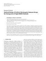
Microstrip patch parameters from
19
FEKO software
RETURN LOSS
PATCH PARAMETERS
OBTAINED VALUES
F
Frequency(Hz)
8.475 Hz
GAIN
Gain(dB)
6.8 dB
Return loss(dB)
-6.8 dB
RESULT OF SIMULATION
20
Used in air borne and spacecraft applications.
Highly suitable for x-band applications.
In satellite and military systems.
APPLICATIONS
21
Simple, Small size and high efficiency antenna can be designed.
Return loss, gain and efficiency are acceptable
Bandwidth enhancement of 20dB is possible
Our future work will be carried out using different feeding techniques
with different software………
CONCLUSION
THANK
22
YOU
QUERIES ????
23