Channel Equalization for Wireless Communications: From Concepts to Detailed Mathematics doc
Bạn đang xem bản rút gọn của tài liệu. Xem và tải ngay bản đầy đủ của tài liệu tại đây (15.29 MB, 244 trang )
Channel Equalization
for Wireless Communications
From Concepts to Detailed Mathematics
Gregory E. Bottom ley
♦IEEE
IEEE Press
IEEE SEMES
ON
DIGITAL
& MOBILE
COMMUNICATION
John B. Anderson, Series Editor
WILEY
A JOHN WILEY & SONS, INC., PUBLICATION
Copyright © 2011 by the Institute of Electrical and Electronics Engineers, Inc.
Published by John Wiley & Sons, Inc., Hoboken, New Jersey. All rights reserved.
Published simultaneously in Canada.
No part of this publication may be reproduced, stored in a retrieval system or transmitted in any form or
by any means, electronic, mechanical, photocopying, recording, scanning or otherwise, except as
permitted under Section 107 or 108 of
the
1976 United States Copyright Act, without either the prior
written permission of
the
Publisher, or authorization through payment of
the
appropriate per-copy fee to
the Copyright Clearance Center, Inc., 222 Rosewood Drive, Danvers, MA 01923, (978) 750-8400, fax
(978) 750-4470, or on the web at www.copyright.com. Requests to the Publisher for permission should
be addressed to the Permissions Department, John Wiley & Sons, Inc., 111 River Street, Hoboken, NJ
07030, (201) 748-6011, fax (201) 748-6008, or online at
Limit of Liability/Disclaimer of
Warranty:
While the publisher and author have used their best efforts in
preparing this book, they make no representation or warranties with respect to the accuracy or
completeness of
the
contents of this book and specifically disclaim any implied warranties of
merchantability or fitness for a particular purpose. No warranty may be created or extended by sales
representatives or written sales materials. The advice and strategies contained herein may not be
suitable for your situation. You should consult with a professional where appropriate. Neither the
publisher nor author shall be liable for any loss of profit or any other commercial damages, including
but not limited to special, incidental, consequential, or other damages.
For general information on our other products and services please contact our Customer Care
Department within the United States at (800) 762-2974, outside the United States at (317) 572-3993 or
fax (317) 572-4002.
Wiley also publishes its books in a variety of electronic formats. Some content that appears in print,
however, may not be available in electronic formats. For more information about Wiley products, visit
our web site at www.wiley.com.
Library of Congress Cataloging-in-Publication Data is available.
ISBN 9780470874271
Printed in the United States of America.
oBook ISBN: 9781118105252
ePDF ISBN: 9781118105283
ePublSBN:9781118105276
MOBI ISBN: 9781118105269
10 987654 3 21
To my colleagues at
Ericsson
CONTENTS IN BRIEF
1 Introduction 1
2 Matched Filtering 31
3 Zero-Forcing Decision Feedback Equalization 57
4 Linear Equalization 69
5 MMSE and ML Decision Feedback Equalization 99
6 Maximum Likelihood Sequence Detection 115
7 Advanced Topics 151
8 Practical Considerations 173
CONTENTS
List of Figures xv
List of Tables xix
Preface xxi
Acknowledgments xxiii
Acronyms xxv
1 Introduction 1
1.1 The Idea 2
1.2 More Details 4
1.2.1 General dispersive and MIMO scenarios 5
1.2.2 Use of complex numbers 7
1.3 The Math 7
1.3.1 Transmitter 9
1.3.2 Channel 11
1.3.3 Receiver 15
1.4 More Math 16
1.4.1 Transmitter 16
1.4.2 Channel 21
1.4.3 Receiver 23
1.5 An Example 24
1.5.1 Reference system and channel models 26
1.6 The Literature 26
X CONTENTS
Problems 27
Matched Filtering 31
2.1 The Idea 31
2.2 More Details 33
2.2.1 General dispersive scenario 34
2.2.2 MIMO scenario 35
2.3 The Math 35
2.3.1 Maximum-likelihood detection 35
2.3.2 Output SNR and error rate performance 37
2.3.3 TDM 38
2.3.4 Maximum SNR 38
2.3.5 Partial MF 41
2.3.6 Fractionally spaced MF 42
2.3.7 Whitened MF 43
2.3.8 The matched filter bound (MFB) 44
2.3.9 MF in colored noise 44
2.3.10 Performance results 45
2.4 More Math 47
2.4.1 Partial MF 49
2.4.2 The matched filter bound 52
2.4.3 MF in colored noise 53
2.4.4 Group matched filtering 53
2.5 An Example 54
2.6 The Literature 54
Problems 55
Zero-Forcing Decision Feedback Equalization 57
3.1 The Idea 57
3.2 More Details 59
3.3 The Math 62
3.3.1 Performance results 63
3.4 More Math 63
3.4.1 Dispersive scenario and TDM 64
3.4.2 MIMO/cochannel scenario 65
3.5 An Example 66
3.6 The Literature 66
Problems 66
Linear Equalization 69
4.1 The Idea 69
4.2
4.3
4.4
4.5
4.6
4.1.1
CONTENTS XI
Minimum mean-square error
More Details
4.2.1
4.2.2
4.2.3
4.2.4
Minimum mean-square error solution
Maximum SINR solution
General dispersive scenario
General MIMO scenario
The Math
4.3.1
4.3.2
4.3.3
4.3.4
4.3.5
4.3.6
MMSE solution
ML solution
Output SINR
Other design criteria
Fractionally spaced linear equalization
Performance results
More Math
4.4.1
4.4.2
4.4.3
4.4.4
4.4.5
4.4.6
4.4.7
4.4.8
ZF solution
MMSE solution
ML solution
Other forms for the CDM case
Other forms for the OFDM case
Simpler models
Block and sub-block forms
Group linear equalization
An Example
The Literature
Problems
72
74
74
75
76
79
79
80
82
83
85
85
86
86
87
87
89
89
91
91
92
93
93
94
95
MMSE and ML Decision Feedback Equalization 99
5.1 The Idea 99
5.2 More Details 101
5.3 The Math 104
5.3.1 MMSE solution 104
5.3.2 ML solution 106
5.3.3 Output SINR 106
5.3.4 Fractionally spaced DFE 106
5.3.5 Performance results 106
5.4 More Math 108
5.4.1 MMSE solution 108
5.4.2 ML solution 109
5.4.3 Simpler models 109
5.4.4 Block and sub-block forms 109
5.4.5 Group decision feedback equalization 110
5.5 An Example 110
XII CONTENTS
5.6 The Literature 110
Problems 112
Maximum Likelihood Sequence Detection 115
6.1 The Idea 115
6.2 More Details 117
6.3 The Math 120
6.3.1 The Viterbi algorithm 120
6.3.2 SISO TDM scenario 125
6.3.3 Given statistics 130
6.3.4 Fractionally spaced MLSD 130
6.3.5 Approximate forms 130
6.3.6 Performance results 131
6.4 More Math 138
6.4.1 Block form 142
6.4.2 Sphere decoding 142
6.4.3 More approximate forms 143
6.5 An Example 144
6.6 The Literature 145
Problems 147
Advanced Topics 151
7.1 The Idea 151
7.1.1 MAP symbol detection 151
7.1.2 Soft information 153
7.1.3 Joint demodulation and decoding 155
7.2 More Details 156
7.2.1 MAP symbol detection 156
7.2.2 Soft information 157
7.2.3 Joint demodulation and decoding 160
7.3 The Math 160
7.3.1 MAP symbol detection 160
7.3.2 Soft information 166
7.3.3 Joint demodulation and decoding 167
7.4 More Math 167
7.5 An Example 167
7.6 The Literature 168
7.6.1 MAP symbol detection 168
7.6.2 Soft information 168
7.6.3 Joint demodulation and decoding 169
Problems 169
CONTENTS XIII
8 Practical Considerations 173
8.1 The Idea 173
8.2 More Details 175
8.2.1 Parameter estimation 175
8.2.2 Equalizer selection 176
8.2.3 Radio aspects 177
8.3 The Math 178
8.3.1 Time-invariant channel and training sequence 179
8.3.2 Time-varying channel and known symbol sequence 180
8.3.3 Time-varying channel and partially known symbol
sequence 181
8.3.4 Per-survivor processing 182
8.4 More practical aspects 182
8.4.1 Acquisition 182
8.4.2 Timing 182
8.4.3 Doppler 183
8.4.4 Channel Delay Estimation 183
8.4.5 Pilot symbol and traffic symbol powers 184
8.4.6 Pilot symbols and multi-antenna transmission 184
8.5 An Example 184
8.6 The Literature 185
Problems 185
Appendix A: Simulation Notes 189
A.l Fading channels 191
A.2 Matched filter and matched filter bound 192
A.3 Simulation calibration 192
Appendix B: Notation 193
References 197
Index 217
LIST OF FIGURES
1.1 Dispersive scenario. 2
1.2 Sampling and digitizing speech. 3
1.3 Received signal example. 4
1.4 Noise histogram for noise power σ
2
= 1. 5
1.5 Dispersive scenario block diagram. 6
1.6 MIMO scenario. 7
1.7 QPSK. 8
1.8 System block diagram showing notation. 8
1.9 16-QAM. 10
1.10 4-ASK with Gray mapping. 11
1.11 Raised cosine function. 12
1.12 Effect of dispersion due to two, 0.75T-spaced, equal amplitude
paths on raised cosine with 0.22
rolloff.
13
1.13 Transmitter block diagram showing parallel multiplexing channels. 17
1.14 OFDM symbol block. 19
2.1 Received signal for matched filtering. 32
xvi LIST OF FIGURES
2.2 Matched filtering block diagram. 32
2.3 BPSK received PDFs. 38
2.4 BER, vs. Eb/Ni) for QPSK, root-raised-cosine pulse shaping (0.22
rolloff), static, two-tap, symbol-spaced channel, with relative
path strengths 0 and —1 dB, and path angles 0 and 90 degrees. 46
2.5 BER vs. E\,/N() for QPSK, root-raised-cosine pulse shaping (0.22
rolloff), static, two-tap, half-symbol-spaced channel, with relative
path strengths 0 and —1 dB, and path angles 0 and 0/90/180
degrees. 47
2.6 OFDM example. 51
3.1 Received signal for DFE. 58
3.2 ZF DFE block diagram. 59
3.3 Traditional DFE. 63
3.4 Alternative DFE. 63
4.1 Received signal for linear equalization. 70
4.2 LE block diagram. 71
4.3 MSE vs. w\ for various values of
W2
for LE. 73
4.4 Example of I + N vs. w\. 76
4.5 BER, vs. Eh/N» for QPSK, root-raised-cosine pulse shaping (0.22
rolloff), static, two-tap, symbol-spaced channel, with relative
path strengths 0 and —1 dB, and path angles 0 and 90 degrees,
LE results. 87
5.1 MSE vs. w\ for various values of
u>2
for DFE for
s-¡.
101
5.2 MMSE DFE block diagram. 102
5.3 BER, vs. Eb/Nf) for QPSK, root-raised-cosine pulse shaping (0.22
rolloff), static, two-tap, symbol-spaced channel, with relative
path strengths 0 and —1 dB, and path angles 0 and 90 degrees,
DFE results. 107
5.4 BER vs. Et,/N[) for QPSK, root-raised-cosine pulse shaping (0.22
rolloff), static, two-tap, symbol-spaced channel, with relative
path strengths 0 and —1 dB, and path angles 0 and 90 degrees,
MMSE LE and DFE results. 108
6.1 MLSD block diagram. 117
6.2 MLSD generation of predicted received values. 118
6.3 MLSD tree diagram. 119
LIST OF FIGURES XVII
6.4 Traveling salesperson problem. 120
6.5 Traveling salesperson tree search. 121
6.6 Traveling salesperson trellis. 122
6.7 MLSD trellis diagram, two-path channel. 123
6.8 MLSD trellis diagram, three-path channel. 123
6.9 Viterbi algorithm flow diagram. 126
6.10 BER vs.
Eb/N
0
for QPSK, root-raised-cosine pulse shaping (0.22
rolloff), static, two-tap, symbol-spaced channel, with relative
path strengths 0 and —1 dB, and path angles 0 and 90 degrees,
single feedback tap. 132
6.11 BER vs. Eb/No for QPSK, root-raised-cosine pulse shaping (0.22
rolloff), static, two-tap, half-symbol-spaced channel, with relative
path strengths 0 and —1 dB, and path angles 0 and 90 degrees, 3
feedback taps. 133
6.12 BER vs. Eb/No for 16-QAM, root-raised-cosine pulse shaping
(0.22 rolloff), static, two-tap, symbol-spaced channel, with
relative path strengths 0 and —1 dB, and path angles 0 and 90
degrees, single feedback tap. 134
6.13 BER vs. Eb/No for QPSK, root-raised-cosine pulse shaping (0.22
rolloff), fading, two-tap, symbol-spaced channel, with relative
path strengths 0 and —1 dB. 135
6.14 BER vs. Eb/No for QPSK, root-raised-cosine pulse shaping (0.22
rolloff), fading, two-tap, symbol-spaced channel, with relative
path strengths 0 and —1 dB, target-C power control. 136
6.15 Cumulative distribution function of effective SINR for QPSK,
root-raised-cosine pulse shaping (0.22 rolloff), fading, two-tap,
symbol-spaced channel, with relative path strengths 0 and —1
dB,
at 6 dB average received Eb/No. 138
6.16 Cumulative distribution function of effective SINR for QPSK,
root-raised-cosine pulse shaping (0.22 rolloff), fading, two-tap,
symbol-spaced channel, with relative path strengths 0 and —1
dB,
at 6 dB target received Eb/No with ideal target-C power
control. 139
6.17 Scatter plot of MMSE DFE effective SINR vs. MMSE LE
effective SINR for QPSK, root-raised-cosine pulse shaping (0.22
rolloff), fading, two-tap, symbol-spaced channel, with relative
path strengths 0 and —1 dB, 6 dB average received Eb/No- 140
XviÜ LIST OF FIGURES
6.18 Scatter plot of MMSE DFE effective SINR vs. MMSE LE
effective SINR for QPSK, root-raised-cosine pulse shaping (0.22
rolloff), fading, two-tap, symbol-spaced channel, with relative
path strengths 0 and
—1
dB, 6 dB received
Eb/N
t)
due to target-C
power control. 141
7.1 MAPSD trellis diagram, three-path channel. 163
7.2 Turbo equalization. 167
8.1 Design choices for adaptive MMSE LE. 176
8.2
Complex plane. 178
LIST OF TABLES
1.1
1.2
1.3
1.4
4.1
6.1
7.1
7.2
7.3
7.4
7.5
7.6
Possible messages
Walsh codes of length 4
TDM codes of length 4
Main block OFDM sequences of length 4
Example of MMSE LE decision variables
Example of sequence metrics
Example of MAPSD symbol metrics
Example of message metrics formed from MAPSD metrics
Example of message metrics formed from MMSE LE metrics
Example of normalized sequence metrics
(7,4) Hamming code bit positions
Example of message metrics for (7,4) Hamming code
2
18
18
20
73
116
153
154
154
157
159
160
XX
Prologue
Alice was nervous. Would Bob receive the message correctly? They were playing
a new cell phone version of Truth or Dare, and Bob had picked Truth. Alice was
given a list of three questions and had selected one to ask him. But Bob was
far from the cell tower that was sending her message to him. Her message was
bouncing off of buildings and arriving at Bob's phone like multiple echoes. Would
Bob's phone be able to figure out the message? Would she be able to receive his
response?
PREFACE
The working title of this book was Channel Equalization for Everyone. Channel
equalization for everyone? Well, for high school students, channel equalization
provides a simple, interesting example of how mathematics and physics can be
used to solve real-world problems. It also introduces them to the way engineers
think, perhaps inspiring them to pursue a degree in engineering. Similar reasoning
applies to first-year undergraduate engineering students.
For senior undergraduate students and graduate students in electrical engineer-
ing, channel equalization is a useful topic in communications. Data rates on wireless
and wireline connections continue to rise, as do information densities on storage de-
vices.
Packing more and more digital symbols in time or space ultimately leads to
intersymbol interference, requiring some form of equalization. Each new communi-
cations air interface or data storage device poses its own challenges, keeping channel
equalization a topic of research as well.
So how can one book be used to teach channel equalization to such different
audiences? Each chapter is divided into the following sections.
1.
The Idea: The idea is described at a level suitable for junior/senior high
school students and first-year undergraduate students with a background in
algebra.
2.
More Details: More information is provided that is intended for senior under-
graduate students but is perhaps more suitable for first-year graduate students
more comfortable with many variables in algebra. Differential calculus and
complex numbers are used in a few places. A little bit of probability theory
xxi
XXÜ PREFACE
is introduced as needed. A set of equations is sometimes written in matrix
form, but linear algebra concepts such as matrix inverses are not used.
3.
The Math: The idea is described in more general, mathematical terms suitable
for second-year graduate students with a background in calculus, communi-
cation theory, linear algebra, and probability theory. To avoid getting lost
in the math, the simple case of time-division multiplexing is considered with
single transmit and receive antennas. Performance results are provided along
with simulation notes.
4.
More Math: The idea is described in even more general terms, considering
symbols multiplexed in parallel (e.g., code-division multiplexing (CDM) and
orthogonal frequency division multiplexing (OFDM)), multiple transmit an-
tennas, and multiple receive antennas. More sophisticated noise models are
also considered.
5.
An Example: The idea is applied to a cellular communications system.
6. The Literature: Bibliographic sources are given as well as helpful references
on advanced topics for further exploration.
Homework problems are also provided, corresponding to the first three sections.
Thus,
a guest lecture for a junior/senior-level high school math class or first-
year undergraduate introductory engineering course can be created from the first
sections of several chapters. The first and second sections can be used to develop
a series of lectures or an entire course for senior undergraduate students. The
remaining sections of each chapter provide the basis for a graduate course and a
foundation for those performing research.
The scope of the book is primarily the understanding of coherent equalization
and the use of digital signal processing (we assume the signal is initially filtered and
sampled). Parameter estimation is briefly touched on in the last chapter, and other
areas such as blind equalization and performance analysis are not addressed. Basic
digital communication theory is introduced where needed, but certain aspects such
as system design for a particular channel are not addressed. Specific mathematical
tools are not described in detail, as such descriptions are available elsewhere. By
keeping the book focused, the hope is that insights and understanding will not get
lost. Such an understanding is important when designing equalization algorithms,
which often involves taking short cuts to keep costs down while maintaining per-
formance.
The book integrates concepts that are often studied separately. Multiple receive
antennas are often studied separately in the array processing literature. Multiple
transmit antennas are sometimes considered separately in the MIMO literature.
Multiple parallel channels are considered in the multiuser detection literature.
My hope is that the reader will discover the joy of solving the puzzle of channel
equalization.
G. E. BOTTOMLEY
Raleigh,
North Carolina
FeJmtary 2011
ACKNOWLEDGMENTS
I would like
to
thank
my
colleagues
at
Ericsson
for
helping
me
learn about equal-
ization
and
giving
me
interesting opportunities
to
develop
and
apply that knowl-
edge.
Another source
of
learning
was the
digital communications textbook
by
John
Proakis [Pro89], which
I
have relied
on
heavily
in
writing this book.
Yet another source
of
learning
was the
IEEE. Much
of the
material
in
this book
is based upon IEEE journal
and
conference publications.
I
appreciate
the
effort
involved
by
authors, reviewers, editors,
and
IEEE
staff. I
would also like
to
thank
Mary Mann, Taisuke Soda,
the
anonymous reviewers,
and the
rest
of the
IEEE
Press
and
Wiley publishing organizations
for
making this book possible.
I would like
to
thank
Prof.
Keith Townsend
for
facilitating
my
stay
at N. C.
State University (NCSU)
as a
Visiting Scholar while writing this book.
I
also need
to thank
him, Prof.
Brian Hughes,
and the
rest
of the
Electrical
and
Computer
Engineering faculty
at
NCSU
for
welcoming
me and
giving
me
good advice.
Finally,
I
would like
to
thank
my
wife,
Dr.
Laura
J.
Bottomley,
for
providing
support
and
encouragement
as
well
as
inspiring
the
concept
of
this book through
her work
as
Director
of
Women
in
Engineering
and
Director
of
Outreach
at the
College
of
Engineering
at N. C.
State University.
G.
E. B.
XXIII
ACRONYMS
AC
A/D
ADC
AMLD
AMPS
ASK
AWGN
BER
BPSK
BCJR
CDF
CDM
CDMA
CRC
D-AMPS
DDFSE
DC
DFE
Alternating Current
Analog-to-Digital
American Digital Cellular
Assisted Maximum Likelihood Detection
Advanced Mobile Phone Service
Amplitude Shift Keying
Additive White Gaussian Noise
Bit Error Rate
Binary Shift Keying
Bahl, Cocke, Jelinek, and Raviv
Cumulative Distribution Function
Code-Division Multiplexing
Code-Division Multiple Access
Cyclic Redundancy Code
Digital Advanced Mobile Phone Service
Delayed Decision-Feedback Sequence Estimation
Direct Current
Decision Feedback Equalization
XXwi ACRONYMS
DFSE
DFT
EDGE
EM
EVDO
FBF
FEC
FF
FFF
FFT
FIR
GMSK
GSM
HSDPA
I/Q
IRC
IS
IS-95
ISI
LDPC
LE
LLF
LLR
LMS
LOS
LSB
LTE
MAP
MAPPD
MAPSD
MF
MFB
MIMO
MISI
MMSE
Decision Feedback Sequence Estimation
Discrete Fourier Transform
Enhanced Data rates for GSM Evolution
Expectation-Maximization
originally EVolution, Data Only, now EVolution, Data Optimized
Feedback Filter
Forward Error Correction
Forward Filter
Feedforward Filter
Fast Fourier Transform
Finite Impulse Response
Gaussian Minimum Shift Keying
Groupe Spéciale Mobile (French), now Global System for Mobile
communications
High Speed Data Packet Access
In-phase/Quadrature
Interference Rejection Combining
Interim Standard
Interim Standard 95, US CDMA
InterSymbol Interference
Low-Density Parity Check
Linear Equalization
Log-Likelihood Function
Log-Likelihood Ratio
Least Mean-Square
Line-Of-Sight
Least Significant Bit
Long Term Evolution
Maximum A Posteriori
MAP Packet Detection
MAP Symbol Detection
Matched Filtering
Matched Filter Bound
Multiple-Input Multiple-Output
Minimum InterSymbol Interference
Minimum Mean-Square Error
ML
MLD
MLPD
MLSD
MLSE
MRC
MSE
MSB
OFDM
PMC
PSP
PZF
QAM
QPSK
r.h.s.
RRC
RSSE
r.v.
SAIC
SINR
SISO
SNR
SP
TDM
TDMA
US CDMA
US TDMA
WCDMA
WMF
w.r.t.
ZF
Maximum Likelihood
Maximum Likelihood Detection
Maximum Likelihood Packet Detection
Maximum Likelihood Sequence Detection
Maximum Likelihood Sequence Estimation
Maximal Ratio Combining
Mean-Square Error
Most Significant Bit
Orthogonal Frequency Division Multiplexing
Probability Density Function
Parallel Multiplexing Channel
Per-Survivor Processing
Partial Zero-Forcing
Quadrature Amplitude Modulation
Quadrature Phase Shift Keying
right-hand side
Root-Raised Cosine
Reduced State Sequence Estimation
random variable
Single Antenna Interference Cancellation
Signal-to-Interference-plus-Noise Ratio
Single-Input Single-Output
Signal-to-Noise Ratio
Set Partitioning
Time-Division Multiplexing
Time-Division Multiple Access
United States CDMA, also IS-95, EVDO
United States TDMA, also D-AMPS, ADC, IS-54,
Wideband CDMA
Whitened Matched Filtering
with respect to
Zero-Forcing
IS-136
CHAPTER 1
INTRODUCTION
In this chapter we will define the problem we are solving and give mathematical
models of the problem, based on the physical laws of nature. Before we do this,
let's jump in with an example.
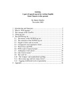
Alice and Bob
Alice has just sent Bob a question in a game of Truth or Dare. The question is
represented by two digital symbols (si and s
2
) as shown in Table 1.1. After sending
an initial symbol so, the symbols are sent one at a time. Each is modified as it
travels along a direct path to the receiver, so that it gets multiplied by —10. The
symbols also travel along a second path, bouncing off a building, as shown in Fig.
1.1. The signal along this path gets multiplied by 9 and delayed so that it arrives
at the same time as the next symbol arrives along the direct path. There is also
noise which is added to the received signal.
At Bob's phone, the received values can be modeled as
Π =
—
10si+9so + rci
r
2
= -10s2+9si+«2
Suppose the actual received values are
ri = 1, r
2
= -7. (1.2)
Channel Equalization for Wireless Communications: From Concepts to Detailed 1
Mathematics, First Edition. Gregory E. Bottomley.
© 2011 Institute of Electrical and Electronics Engineers, Inc. Published 2011 by John Wiley & Sons, Inc.
(1.1)
2 INTRODUCTION
Table 1.1 Possible messages
Index Representation Message
Si S2
1 +1—1 "Do you like classical music?"
2 -1 -1 "Do you like soccer?"
3 +1+1 "Do you like me?"
Figure 1.1 Dispersive scenario.
Which message was sent? How would you figure it out? Would it help if symbol So
were known or thought to be +1? Think about different approaches for determining
the transmitted symbols. Try them out. Do they give the same answer? Do they
give valid answers (the sequence si =
— 1
S2 = +1 is not in the table)?
1.1 THE IDEA
Channel equalization is about solving the problem of intersymbol interference (ISI).
What is ISI? First, information can be represented as digital symbols. Letters
and words on computers are represented using the symbols 0 and 1. Speech and
music are represented using integers by sampling the signal, as shown in Fig. 1.2.
These numbers can be converted into base 2. Thus, the number 6 becomes 110
(0x1 + 1x2+1x4). There are different ways of mapping the symbols 0 and 1
into values for transmission. One mapping is to represent 0 with +1 and 1 with
—
1.
Thus, 110 is transmitted as using the series —1 —1 +1. The symbols 0 and 1
are often referred to as Boolean values. The transmitted values are called modem
symbols or simply symbols.
ISI is the interference between symbols that can occur at the receiver. In the
Alice and Bob example, we saw that one symbol was interfered by a previous symbol
due to a second signal path. This is a problem in cell phone communications, and
we will refer to it as the dispersive channel scenario. A cell tower transmitter sends
THE IDEA 3
Figure 1.2 Sampling and digitizing speech.
a series or packet of digital symbols to a cell phone. The transmitted signal travels
through the air, often bouncing off of walls and buildings, before arriving at the cell
phone receiver. The receiver's job is to figure out what symbols were sent. This is
an example of the channel equalization problem.
To solve this problem, we would like a mathematical model of what is happening.
The model should be based on the laws of physics. Cell phone signals are transmit-
ted using electromagnetic (radio) waves. The signal travels through the air, along
a path to the receiver. From the laws of physics, the effect of this "channel" is
multiplication by a channel coefficient. Thus, if s is the transmitted symbol, then
cs is the received symbol, where c is a channel coefficient. To keep things simple,
we will assume c is a real number (e.g., —10), though in practice it is a complex
number with real and imaginary parts (amplitude and phase).
Sometimes the channel is dispersive, so that the signal travels along multiple
paths with different path lengths, as illustrated in Fig. 1.1. The first path goes
directly from the transmitter to the receiver and has channel coefficient c = —10.
The second path bounces off a building, so it is longer, which delays the signal like
an echo. It has channel coefficient d = 9. There is also noise present. The overall
mathematical model of the received signal values is given in (1.1). The portion of
the received signal containing the transmitted symbols is illustrated in Fig. 1.3.
Notice that the model includes terms n\, rii to model random noise. The laws
of physics tell us that electrons bounce around randomly, more so at higher tem-
peratures. We call this thermal noise. Such noise adds to the received signal.