- Trang chủ >>
- Khoa Học Tự Nhiên >>
- Vật lý
Intermediate fluid mechanics [ME563 course notes]
Bạn đang xem bản rút gọn của tài liệu. Xem và tải ngay bản đầy đủ của tài liệu tại đây (34.5 MB, 221 trang )
ME 563 - Intermediate Fluid Dynamics - Su
Lecture 0 - Visual fluids examples
Fluid dynamics is a unique subject because it’s very visual. The book “An Album of Fluid Mo-
tion” by Milton van Dyke (on reserve at Wendt) is a collection of fascinating images from fluids
experiments. You really can’t say you understand fluids if you only think of it in terms of equations.
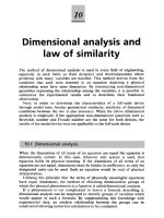
Figure 1 is a top view of a triangular wing immersed in a flow of water (moving from left to right
in the image). Colored fluid, appearing as white, is introduced near the leading edge. The wing
Figure 1: Turbulent transition in flow over a wing.
is inclined at a 20
◦
angle of attack. Initially the fluid pattern is very smooth, then the filaments
of colored fluid make a very abrupt transition to turbulence. The abruptness of the turbulent
transition is interesting for many reasons, not least of which is that it’s not really predicted by the
equations of fluid flow.
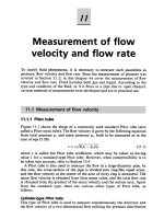
Another interesting property of fluid flows is that the organization of it is very persistent. The
upper left photo in Fig. 2 is of the wake of a circular cylinder in a water flow. The cylinder is at
the left edge of the photo. The mean flow is very slow – about one cylinder diameter per second.
The Reynolds number is 105. The alternating pattern of eddies (vortices) is called the ‘K`arm`an
vortex street.’ Intuitively, it kind of makes sense that a slow, laminar flow would be very organized.
The upper right photo in Fig. 2, showing the wake of a plate at a 45
◦
angle of attack, is taken at
a flow that is, relatively, about 40 times faster (Reynolds number 4300). The flow in this case is
turbulent, but even so, the alternating pattern of eddies is visible above the randomness. To drive
home this point further, the lower photo in the figure is of the wake of a tanker inclined at roughly
45
◦
to the mean current. The pattern assumed by the oil slick is amazingly similar to that in the
upper right photo, even though the Reynolds number of the ship wake is on the order of 10
7
.
The sheer range of length scales that are interesting in fluids problems is pretty remarkable too.
Active research ranges from flow in microchannels (blood flow in capillaries, for example) all the
way up to cosmic systems like nebulae. The upper left photo in Fig. 3 shows the Kelvin-Helmholtz
instability, which arises in the interface between flow streams at different velocities. The photo
shows a rectangular tube (the 18 inch ruler in the image shows the scale), with pure water moving
left-to-right on top and colored salt water moving right-to-left below. The upper image on the right
is of clouds near Denver. On the leeward (sheltered) side of mountain ranges, you will often have
layers of high winds above relatively slow air. When clouds sit near the interfaces, these Kelvin-
Helmholtz structures result. Needless to say, the cloud structures are much bigger than those seen
in the lab, but the math is the same. (The cloud image is taken from “Hydrodynamic Stability”
by Drazin and Reid, also on reserve.)
1
Figure 2: Persistence of flow organization, for Reynolds numbers spanning five orders of magnitude.
Figure 3: Fluid problems span a vast range of length scales.
2
ME 563 - Intermediate Fluid Dynamics - Su
Lecture 1 - Math fundamentals
The subject of fluid dynamics brings to mind pipes, pumps, wind tunnels, fans and any number
of other engineering devices. However, to study fluid dynamics effectively requires some basic
mathematical tools. (Interestingly, while fluid dynamics is thought to be very much the domain of
engineers, much work in fluids, particularly in Europe, is performed in applied math, math, applied
physics and physics departments.) In this class it will be assumed that you are familiar with the
basic techniques of differentiation and integration, partial derivatives, differential equations and
vector calculus. You may not remember everything from your math courses but you should at
least know where to find things (tables of integrals, for example). What is important is your
mathematical intuition.
The following expression should look vaguely familiar:
lim
∆x→0
f(x
0
+∆x)−f(x
0
−∆x)
2∆x
=?
If a function f (x) is differentiable at a point x
0
, then this gives the value of the derivative, f
(x
0
),
at that point, that is
lim
∆x→0
f(x
0
+∆x)−f(x
0
−∆x)
2∆x
= f
(x
0
)iffis differentiable at x
0
.(1)
This expression gives the value of f
(x
0
)iff is differentiable, but just because the limit in (1)
exists doesn’t mean that f is differentiable at x
0
(what’s a counterexample?). It turns out, if the
one-sided limits are equal –
lim
∆x→0
f(x
0
+∆x)−f(x
0
)
∆x
= lim
∆x→0
f(x
0
) −f(x
0
− ∆x)
∆x
(with ∆x>0) (2)
then f is differentiable at x
0
,andf
(x
0
) is equal to the value of the one-sided limits of (2), which
is then equal to the two-sided limit of (1).
Thinking of derivatives in terms of differences (hopefully) seems completely trivial, but un-
derstanding (1) and (2) implicitly is key to subjects like fluids that rely heavily on differential
equations (and if it were easy, it wouldn’t have taken Isaac Newton to come up with calculus).
This is especially true since data (whether experimental or computational) is digital, and discrete
math is used extensively.
1 Vector analysis
Vector analysis is vital to fluid mechanics because the most fundamental descriptive quantity in
fluid flow, the velocity, is a vector. We’ll start with the three-dimensional Cartesian coordinate
system with unit vectors ˆe
x
,ˆe
y
and ˆe
z
. Consider the vectors a = a
x
ˆe
x
+ a
y
ˆe
y
+ a
z
ˆe
z
and b =
b
x
ˆe
x
+ b
y
ˆe
y
+ b
z
ˆe
z
. The dot product (or scalar product) of a and b is
a ·b = |a||b|cos θ = a
x
b
x
+ a
y
b
y
+ a
z
b
z
(3)
where |·|denotes the length, or magnitude, of a vector, and θ is the angle between the vectors.
The cross product (or vector product) of a and b, a × b, is more complicated. Its magnitude
is given by
|a ×b| = |a||b|sin θ
1
Figure 1: The direction of the cross product a × b.
where θ is the (smallest) angle between a and b (i.e. θ ≤ 180
◦
). The direction of a × b is perpen-
dicular to the plane of a and b, in the right-hand sense of rotation from a to b through the angle θ
(Fig. 1). Because of this direction definition, the cross product anti-commutes, i.e. a ×b = −b ×a.
It turns out that the most convenient way to express the cross product is as a determinant –
a ×b =
ˆe
x
ˆe
y
ˆe
z
a
x
a
y
a
z
b
x
b
y
b
z
=(a
y
b
z
−a
z
b
y
)ˆe
x
+(a
z
b
x
−a
x
b
z
)ˆe
y
+(a
x
b
y
−a
y
b
x
)ˆe
z
(4)
Easily seen through (4) are the identities ˆe
x
× ˆe
y
=ˆe
z
,ˆe
y
׈e
z
=ˆe
x
,andˆe
z
׈e
x
=ˆe
y
.
Of particular interest is the operator ∇ (variously called the gradient operator, del operator, or
grad operator). We can write ∇ as
∇ =ˆe
x
∂
∂x
+ˆe
y
∂
∂y
+ˆe
z
∂
∂z
(5)
∇ has no meaning unless it’s operating on something. The familiar operations are the gradient,
the divergence, the curl, and the Laplacian.
1.1 The gradient and directional derivative
When ∇ operates on a scalar quantity, φ(x, y, z), the result is called the gradient of φ,andis
written
∇φ =ˆe
x
∂φ
∂x
+ˆe
y
∂φ
∂y
+ˆe
z
∂φ
∂z
(6)
To interpret this, consider a unit vector
ˆ
s = s
x
ˆe
x
+ s
y
ˆe
y
+ s
z
ˆe
z
,andletsbe the distance variable
along this vector. Without loss of generality, we will assume that s = 0 at the origin, x = 0. Then,
the coordinates of any point on the s-axis are
x = s
x
s
y = s
y
s
z = s
z
s (7)
Suppose we want to know the rate of change of φ in the s direction, at the origin. This dφ/ds is
also known as the directional derivative. By the chain rule, this can be written (note the selective
use of partial derivatives)
dφ
ds
=
∂φ
∂x
dx
ds
+
∂φ
∂y
dy
ds
+
∂φ
∂z
dz
ds
=
∂φ
∂x
s
x
+
∂φ
∂y
s
y
+
∂φ
∂z
s
z
(8)
2
Figure 2: Sample volume for illustrating the divergence.
where we have used (7). By inspection, we have
dφ
ds
= ∇φ ·
ˆ
s (9)
that is, the rate of change of a scalar function φ in an arbitrary direction is equal to the scalar
product of the gradient ∇φ with the unit vector,
ˆ
s, in that direction. Using (3), we can also write
(since |
ˆ
s|=1)
dφ
ds
= |∇φ|cos θ (10)
where θ is the angle between ∇φ and ˆe
s
. So we can also say that dφ/ds is the projection of ∇φ
onto the direction s. Finally, observe from (10) that ∇φ is perpendicular to lines of constant φ.
1.2 The divergence and divergence theorem
Now let’s consider what happens when we apply ∇ to vector quantities. Consider a vector field
f = f
x
ˆe
x
+ f
y
ˆe
y
+ f
z
ˆe
z
. (We call this a vector ‘field’ because it’s defined over a volume in space,
not just at a single point.) The dot product of ∇ with f is called the divergence,andisgivenby
∇·f =
∂f
x
∂x
+
∂f
y
∂y
+
∂f
z
∂z
(11)
To understand the name ‘divergence’, let the three-dimensional volume V be a cube with
infinitesimal side lengths dx = dy = dz, as in Fig. 2. We can write the volume of V as dx dy dz = dV .
Assume that on each face of the cube, f is constant. Now consider face 1 in the figure. The
component of f that points out of the cube on face 1 is f
x
. Because f is constant on the face,
we can write this as f
x
(x = dx). On face 4, the component of f that points out of the cube is
−f
x
(x = 0). The area of each of these two faces is dy · dz, so the net volume flux out of the cube
through faces 1 and 4 can be written
Flux out of faces 1 and 4 = [f
x
(x = dx) − f
x
(x =0)]dy dz (12)
We can go through similar arguments for the remaining faces, and we get
Flux out of faces 2 and 5 = [f
y
(y = dy) − f
y
(y =0)]dx dz
Flux out of faces 3 and 6 = [f
z
(z = dz) − f
z
(z =0)]dx dy (13)
3
Now notice that we can rewrite (12) as
[f
x
(x = dx) − f
x
(x =0)]dy dz =
f
x
(x = dx) − f
x
(x =0)
dx
dx dy dz
=
f
x
(x = dx) − f
x
(x =0)
dx
dV
≈
∂f
x
∂x
dV (14)
where the last part is true in the limit of dx approaching zero. Similarly, the flux out of faces 2
and 5 can be written (∂f
y
/∂y) dV , and out of faces 3 and 6 can be written (∂f
z
/∂z) dV . Referring
back to (11), given a vector f , the net volume flux out of the volume dV equals the product of ∇·f
and dV .Thus∇·f is a measure of the spread, or divergence, of the vector field f .
This somewhat non-rigorous analysis can be generalized as the divergence theorem.Given
an arbitrary volume V , enclosed by the surface S, with outward unit normal vector n at all points
on S, the divergence theorem states
V
∇·fdV =
S
f ·n dS. (15)
This will be very useful when we get to the equations for fluid flow.
1.3 The curl and Stokes’ theorem
The cross product of ∇ with the vector f is called the curl,andisgivenby
∇×f =
ˆe
x
ˆe
y
ˆe
z
∂
∂x
∂
∂y
∂
∂z
f
x
f
y
f
z
=
∂f
z
∂y
−
∂f
y
∂z
ˆe
x
+
∂f
x
∂z
−
∂f
z
∂x
ˆe
y
+
∂f
y
∂x
−
∂f
x
∂y
ˆe
z
(16)
To see where the term ‘curl’ comes from, look at Fig. 2 again, but this time only consider face
6. Call this the surface S,withareadx dy = dS. We’ll define a direction of travel around the
border of S in the counter-clockwise direction. Assume also that the vector field f is constant on
each edge of S. Starting at the the origin, we first travel along the edge defined by y =0. The
component of f parallel to the direction of travel on this edge is f
x
(y = 0). We can then define a
contour integral (a sort of net travel) as f
x
(y =0)dx. The next edge is the one defined by x = dx,
along which the net travel f
y
(x = dx) dy. Going all the way back around to the origin, we end up
with (taking care with the signs)
Net travel = f
x
(y =0)dx + f
y
(x = dx) dy − f
x
(y = dy)) dx − f
y
(x =0))dy
=[f
y
(x=dx) −f
y
(x =0)]dy − [f
x
(y = dy) − f
x
(y =0)]dx
=
f
y
(x = dx) − f
y
(x =0)
dx
dS −
f
x
(y = dy) − f
x
(y =0)
dy
dS
≈
∂f
y
∂x
−
∂f
x
∂y
dS (17)
Again, this last expression is true for dx and dy approaching zero. Comparing with (16), (17) is
just the z-component of ∇×f. By the direction convention for integration around a closed contour,
ˆe
z
is the normal vector for face 6 (our surface S) in Fig. 2 for the counter-clockwise integration
direction. Thus, the integral of f around the contour enclosing S equals the component of ∇×f
in the direction normal to S multiplied by dS. In the context of the integration around the closed
contour, the use of the term ‘curl’ is obvious.
4
Figure 3: Direction convention for integration around a closed contour, C. The vector
ˆ
n is the unit
normal to the surface.
Stokes’ theorem generalizes this. Let S be a two-dimensional surface enclosed by the curve
C.Then
S
(∇×f)·ndS =
C
f ·dx (18)
where the direction of the line integral relates to the direction of the normal vector n in the right-
hand sense (Fig. 3).
1.4 The Laplacian
If we take the divergence of a gradient, we get the Laplacian, which is defined (φ is a scalar)
∇
2
φ = ∇·(∇φ)=
∂
2
φ
∂x
2
+
∂
2
φ
∂y
2
+
∂
2
φ
∂z
2
(19)
applying (6) and (11). The Laplacian is interesting in relation to quantities that undergo gradient
diffusion. An example is heat, which diffuses proportionally to the gradient in temperature. If we
let φ be the temperature and κ be the thermal diffusivity, then the temperature flux vector can be
written (note the minus sign)
Temperature flux vector = −κ∇φ (20)
The Laplacian can thus be interpreted by substituting −∇φ for f in the discussion of the divergence
in Sec. 1.2. That is, the Laplacian describes the net flux of the scalar quantity into avolume.
Consider a uniform temperature field with a sharp positive spike somewhere in it. The spike will
have a strongly negative Laplacian value, which means that heat will flow out from the region of
the spike, which makes sense, since diffusivity tends to smooth out sharp gradients. Another scalar
quantity that undergoes gradient diffusion is species concentration – a vector quantity that does is
momentum, but we will need more math tools to consider the diffusion of vector quantities.
5
ME 563 - Intermediate Fluid Dynamics - Su
Lecture 2 - More math, plus some basic physics
In the first lecture we went over some basic math concepts, in particular the operator ∇. We’ll
finish up with basic math by going over tensors and index notation, then talk about some basic
physical concepts.
1 Tensors and index notation
In the last lecture we considered the dot product, where two vectors result in a scalar, and the
cross product, where the two vectors yield a third vector. There is another way to multiply vectors
together that gives rise not to a scalar or a vector, but to a tensor. To deal with those it’s most
convenient to use index notation (also called tensor notation).
1.1 Index notation
Scalars and vectors are actually specific cases of tensors. A scalar is a tensor of order (or rank)
zero, and a vector is a tensor of order one. (Generally, however, if we say that something is a tensor
without specifying its order, we will mean that it is a tensor of order two.) The order of a tensor
tells you the number of indices necessary to describe it. In n-dimensional space, a tensor of order
m has n
m
components.
We can repeat some of the results of the last lecture using index notation. Consider a vector f
defined in three-dimensional space. Let the three orthogonal unit vectors be ˆe
1
,ˆe
2
,andˆe
3
.(We’re
not using x, y and z because the coordinate system is not necessarily Cartesian, or it could be
rotated from x, y and z, etc.) Then we can write f as
f = f
1
ˆe
1
+ f
2
ˆe
2
+ f
3
ˆe
3
= f
i
ˆe
i
(1)
This expression illustrates two key aspects of index notation:
• An index (in this case i) takes on values corresponding to the number of dimensions in the
space being considered.
• If an index is repeated in a term, then that term is summed over that index (this is the
summation convention, which physicists call the Einstein summation convention).
The dot product and cross product of two vectors can be expressed conveniently in index
notation, with the aid of two new operators. The dot product of two vectors a and b is
a ·b = a
i
b
j
δ
ij
, where δ
ij
=
1ifi=j
0ifi=j.
(2)
This δ
ij
is called the Kronecker delta. (Of course, we could also have written a ·b = a
i
b
i
using the
summation convention.) The cross product of a and b is
a ×b =
ijk
a
j
b
k
ˆe
i
, where
ijk
=
1ifijk is cyclic, i.e. 123, 231, or 312
−1ifijk is anti-cyclic, i.e. 321, 213, 132
0 if any of the two indices are identical.
(3)
The
ijk
is called the permutation tensor or permutation operator.
1
1.2 Tensors
Consider two vectors a = a
1
ˆe
1
+ a
2
ˆe
2
+ a
3
ˆe
3
= a
i
ˆe
i
and b = b
1
ˆe
1
+ b
2
ˆe
2
+ b
3
ˆe
3
= b
i
ˆe
i
. If we multiply
them together, not as a dot product or cross product, but just ab,wegetab = T,or
ab = a
i
b
j
=
a
1
b
1
a
1
b
2
a
1
b
3
a
2
b
1
a
2
b
2
a
2
b
3
a
3
b
1
a
3
b
2
a
3
b
3
= T
ij
= T (4)
where, by convention, the first index, here i, represents the row of the tensor and the second index,
j, represents the column. Also, a quick notational point. The order of a tensor is sometimes
identified by underlining. So a vector a is often written a
, and a tensor T is often written T .
The underlining convention is common with written work; in printed work, vectors and tensors are
usually just represented in boldface (some authors use lowercase bold for vectors and uppercase
bold for tensors, but this isn’t universal).
Because the first index in a tensor represents the row, and a vector is a tensor of order one, the
vector a can be written
a = a
i
ˆe
i
=
a
1
a
2
a
3
. (5)
The matrix representation of a is not written with the unit vectors ˆe
i
because in tensor form, the
unit vectors are assumed to go with the components i (this can sometimes be confusing).
The transpose of a tensor is a tensor with its rows and columns switched. For a second-order
tensor T, this means the transpose T
T
is given by
for T = T
ij
=
T
11
T
12
T
13
T
21
T
22
T
23
T
31
T
32
T
33
, the transpose is T
T
= T
ji
=
T
11
T
21
T
31
T
12
T
22
T
32
T
13
T
23
T
33
. (6)
In the expression for the transpose, when we write T
T
= T
ji
, the first index still corresponds to the
row even though we use j instead of i. A tensor T is called symmetric if T = T
T
, i.e. if T
ij
= T
ji
.
A tensor T is anti-symmetric if T = −T
T
,orT
ij
= −T
ji
.
For a vector a, taking the transpose just means
for a =
a
1
a
2
a
3
, the transpose is a
T
=
a
1
a
2
a
3
. (7)
The standard rules of matrix multiplication can be applied to tensors. Matrix multiplication
corresponds to the dot product. It is possible to take the dot product of a tensor T and a vector
a –
T ·a = T
ij
a
j
=
T
11
T
12
T
13
T
21
T
22
T
23
T
31
T
32
T
33
a
1
a
2
a
3
=
T
11
a
1
+ T
12
a
2
+ T
13
a
3
T
21
a
1
+ T
22
a
2
+ T
23
a
3
T
31
a
1
+ T
32
a
2
+ T
33
a
3
(8)
(Notice the application of the summation convention.) The dot product in this case doesn’t yield
a scalar, but instead a vector. The dot product essentially gives a result one order reduced from
the highest order tensor in the product. This leads to the other form of multiplication we’ll be
interested in, the double-dot product (also known as the scalar product for tensors). This takes
two second-order tensors and yields a scalar, as
T : T = T
ij
T
ij
. (9)
2
1.3 Velocity gradient tensor
The tensor we will be most interested in is the velocity gradient tensor, ∇u. For Cartesian coordi-
nates, with u = uˆe
x
+ vˆe
y
+ wˆe
z
, ∇u is defined as
∇u =
∂u
j
∂x
i
=
∂u
∂x
∂v
∂x
∂w
∂x
∂u
∂y
∂v
∂y
∂w
∂y
∂u
∂z
∂v
∂z
∂w
∂z
(10)
The Laplacian of the velocity, ∇
2
u, will also appear often in our discussions. This is found by
∇
2
u = ∇·(∇u)=
∂
∂x
∂
∂y
∂
∂z
∂u
∂x
∂v
∂x
∂w
∂x
∂u
∂y
∂v
∂y
∂w
∂y
∂u
∂z
∂v
∂z
∂w
∂z
=
∂
2
u
∂x
2
+
∂
2
u
∂y
2
+
∂
2
u
∂z
2
∂
2
v
∂x
2
+
∂
2
v
∂y
2
+
∂
2
v
∂z
2
∂
2
w
∂x
2
+
∂
2
w
∂y
2
+
∂
2
w
∂z
2
=
∇
2
u
∇
2
v
∇
2
w
(11)
so taking the Laplacian of the velocity vector is equivalent to taking the Laplacian of each of the
components.
(We’ll talk about the physical meaning of ∇u in detail later.)
2 Physical concepts
Let’s now discuss some basic physical ideas. One of the goals of this class is to develop the ability
to think through problems intuitively before having to bring math tools to bear. Suppose I have
two airplanes. They are identical except one of them has winglets on the wingtips, like you see on
some airliners (747’s, A340’s etc.).
Figure 1: Two wings: wing 1, no winglet, wing 2, winglet.
The first wing shows a tip vortex, while the second doesn’t.
Figure 2: Tip vortex on wing 1.
Why does this tip vortex arise? First, we know that wings are designed to provide elevated
pressures on the lower surface, and reduced pressures on the upper surface. However, if we pick a
point just outside of the wingtip, the pressure has to be the same from above and below, because
3
the pressure can’t have a discontinuity. As a result, the pressure on the underside of the wing is
gradually reduced as we approach the tip, and the pressure above the wing is gradually increased
as we approach the tip, so the pressures become equal outside the tip. Because fluids move in the
Figure 3: Pressure distribution around a wing.
direction of decreasing pressure, the airflow on the lower surface of the wing moves toward the tip,
and the airflow on the lower surface moves toward the plane’s fuselage. Put together, the result
is a tip vortex with the sense of rotation shown in Fig. 2. (The winglet in wing 2 is designed to
prevent the formation of this vortex.) Basically, two principles (and no math) were necessary to
show this - the idea that pressure fields are continuous, and that flows are driven in the direction
of decreasing pressure.
Why, though, would a designer want to get rid of the tip vortex? Let’s consider what effect
the tip vortex has by imagining that we’re stationary in space, and can somehow see the velocity
of the air. A plane equipped with winglets passes, leaving the air essentially undisturbed. A plane
without winglets passes, and in contrast we see the air spinning off the wingtips. The subsequent
reasoning goes like this:
• The flow with the vortical structures has more kinetic energy than the undisturbed flow.
• The kinetic energy has to be provided by the plane’s engines.
• The energy provided by the engines to the vortices is energy not provided to the plane’s
forward motion.
• The vortices thus correlate with an effective drag force on the plane.
We’ve thus shown that the tip vortices cause drag, and we needed to apply only the conservation
of energy, again with no math. Unfortunately not all problems can be solved with just physical
intuition, but physical intuition is still very handy.
4
ME 563 - Intermediate Fluid Dynamics - Su
Lecture 3 - Basic concepts of ideal fluids / Euler’s equations
Reading: Acheson, chapter 1.
In describing fluid flow it is common to speak of the velocity field, u = u(x,t), which gives
the value of the velocity vector, u, at all points x and times t. (In Cartesian coordinates, u =
u ˆe
x
+ v ˆe
y
+ w ˆe
z
=(u, v, w)andx=xˆe
x
+yˆe
y
+zˆe
z
=(x, y, z).) The following basic notions will
be used extensively.
• A steady flow is one where the velocity is a function of spatial position only, i.e. u = u(x),
and ∂u/∂t =0.
• Atwo-dimensional flow is one in which the velocity is independent of one spatial direction, and
there is no velocity component in that direction. In Cartesian coordinates, u = u(x, y, t)ˆe
x
+
v(x, y, t)ˆe
y
is an example of a two-dimensional flow.
• A streamline is a curve that is parallel to the local velocity vector at all points. Suppose s
is a variable that measures the distance traveled along a particular streamline. In Cartesian
coordinates, a streamline would be expressed x = x(s), y = y(s), z = z(s). At any point on
the streamline, dx/dy = u/v, dy/dz = v/w,anddx/dz = u/w (compare Eq. 1.5 in the book).
• The material derivative Df/Dt describes the rate of change of a quantity f in a reference
frame following the fluid. It is defined
Df
Dt
=
∂f
∂t
+ u
∂f
∂x
+ v
∂f
∂y
+ w
∂f
∂z
=
∂f
∂t
+(u·∇)f =
∂f
∂t
+ u ·(∇f). (1)
The velocity components u, v and w appear courtesy of the chain rule. This Df/Dt is also
known as the substantial derivative or particle derivative. The process described by Df/Dt
is known as advection, and involves the change in f due only to the motion of the fluid. Other
factors can affect f and must be dealt with separately (examples to follow).
1 Ideal fluids
An ideal fluid is one for which the following conditions hold –
1. It is incompressible. In practice, this generally means that the density, ρ, is a constant
throughout the fluid.
2. It is inviscid. Thus, the only force acting across any surface element dS in the fluid is the
pressure.
Strictly speaking, the property of incompressibility is better ascribed to the flow than the fluid.
For example, gases are obviously compressible, but under certain conditions (specifically, low Mach
number) their flows can be treated as incompressible.
1
Figure 1: An infinitesimal cubic volume V .
1.1 Equations of motion for an ideal fluid
To get the equations of motion for an ideal fluid, we might reasonably expect to use the familiar
conservation properties from physics: conservation of mass, momentum, and energy. Sure enough,
the first equation of motion describes the conservation of mass. Let V be an arbitrary volume in
the fluid, enclosed by the surface S. Because the density of the fluid is constant, the net volume
flux across the surface S has to be zero. By the divergence theorem, this means –
V
∇·udV = 0 for any arbitrary volume V. (2)
We can make this statement stronger. Suppose that ∇·u is positive (or negative) at some point
x
0
. Assuming that the ∇·u is continuous, then we can define a volume V around x
0
such that
∇·u is positive (or negative) at all points in V . But then this violates (2). Thus, the conservation
of mass leads to the first equation of motion for an ideal fluid, namely
∇·u= 0 everywhere in an ideal fluid. (3)
Now for the conservation of momentum. Again, we let V be some arbitrary volume enclosed by
S. By the second property of ideal fluids listed above, the only forces acting across S are pressure
forces. We are interested in the forces acting on the fluid in V ; we are not interested here in
the forces applied by the fluid contained in V . The net force exerted on the fluid in V by the
surrounding fluid is
−
S
pn dS (4)
where the minus sign indicates that the force vector points into V in the direction of the normal
vector to S. To cast this in a more convenient form, we’ll again do an analysis similar to what we
did to illustrate the divergence in Lecture 1. Figure 1 is the same infinitesimal cubic volume V ,
with volume dV = dx dy dz, that we used before. The pressure force applied by the surrounding
fluid on face 1 is −p(x = dx) dy dz ˆe
x
,andonface4isp(x=0)dy dz ˆe
x
.(Asbefore,wehave
assumed that p is constant on each face.) The other faces can be treated analogously. We get
Pressure force on faces 1 and 4 = −[p(x = dx) −p(x =0)]dy dz ˆe
x
Pressure force on faces 2 and 5 = −[p(y = dy) − p(y =0)]dx dz ˆe
y
Pressure force on faces 3 and 6 = −[p(z = dz) − p(z =0)]dx dy ˆe
z
. (5)
2
Look at the force on faces 1 and 4. We can rewrite that component as
−[p(x = dx) − p(x =0)]dy dz ˆe
x
= −
p(x = dx) −p(x =0)
dx
dV ˆe
x
≈−
∂p
∂x
dV ˆe
x
. (6)
Compiling the x-, y-andz-components, and recalling the definition of the gradient, we get –
Net pressure force on V = −
∂p
∂x
dV ˆe
x
−
∂p
∂y
dV ˆe
y
−
∂p
∂z
dV ˆe
z
=(−∇p) dV, (7)
which tells us the net pressure force on the infinitesimal volume element. (Notational point: the
text calls the volume δV .)
Besides the pressure force, we will also allow for gravitational forces on our volume element –
Gravitational force on V = m
V
g = ρ g dV (8)
where m
V
= ρdV is the mass of fluid contained in V . Adding (8) to (7), we get
Total force on V =(−∇p + ρ g) dV (9)
This applied force has to be equal to the rate of change of the linear momentum of the fluid in V
(the product of its mass and acceleration), that is,
Mass × acceleration of the fluid in V = ρdV
Du
Dt
(10)
where we have used the material derivative to express the acceleration of the fluid. We do this
because the the forces described by (9) act on the fluid contained in V at a particular instant in
time. Any changes in momentum effected by those forces are manifested in that parcel of fluid
(what the book calls a ‘blob’) as it moves. The material derivative is thus relevant because it is
the derivative that follows the fluid.
Equating (10) and (9), we get the remaining equations of motion for an ideal fluid,
Du
Dt
= −
1
ρ
∇p + g. (11)
In general, (11) represents three equations, one for each dimension. They are nonlinear partial
differential equations. Together, (3) and (11) are called Euler’s equations of motion for an ideal
fluid.
(We didn’t use the conservation of energy in deriving Euler’s equations. Energy will become
interesting when we talk about viscous fluids.)
3
Lecture 5 - Limitations of ideal fluid theory / role of viscosity
Reading: Acheson, chapter 1, chapter 2 (through §2.3).
In the last lecture we introduced the concept of circulation, which we defined as –
Γ=
C
u·dx
where C is a closed curve. The circulation around an airfoil explains the lift generated. Consider
the airfoil in Fig. 1, surrounded by a curve C, along which we will compute the circulation in the
direction indicated. Assume that the mean airflow is horizontal, from left to right, in the reference
Figure 1: Computation of the circulation around a wing.
frame where the wing is stationary.
To compute the circulation, first assume that the sides labeled 2 and 4 are far enough away
from the wing that the flow has no vertical component there, so u · dx = 0 on those sides. Also,
because C is a rectangle, sides 1 and 3 have the same length, but on side 1 we integrate in the
positive x-direction and on side 3 we integrate in the negative x-direction. The circulation around
C then becomes
Γ=
side 1
udx+
side 3
−udx
=
(
side 1
u −
side 3
u ) dx. (1)
What do we know about the values of u above and below the wing? We can assume that the
flow is steady and irrotational, and that gravity is negligible. By the (second) Bernoulli theorem,
p +
1
2
ρ|u|
2
is constant everywhere. For the wing to have lift, the pressure on the lower surface has
to be greater than that on the upper surface, which then means that the air speed below the wing
(along side 3 of C) has to be less than the air speed above the wing (side 1 of C). From (1), this
means that the circulation, Γ, is negative (for the direction of integration defined in Fig. 1).
Bernoulli’s theorems are formulated for ideal fluids, and while real fluids aren’t ideal, ideal fluid
theory does a good job of predicting lift for airfoils at small angles of attack. (At high angles of
attack, ideal fluid theory fails rapidly, as in Fig. 1.11 in the text.) We have shown that the lift of
an airfoil depends on the circulation around it. Let’s think a little bit more about the circulation
being nonzero.
Specifically:
• We have assumed that the mean flow in which we’ve immersed our wing is irrotational (has
zero vorticity), that the flow around the wing can be treated as two-dimensional. These are
perfectly valid assumptions.
1
• By Stokes’s theorem, we showed that the circulation around a curve C is zero if the vorticity
is zero over the entire surface S bounded by C.
• By considering the vorticity equation in the last lecture, we showed that for two-dimensional
flows of ideal fluid subject to conservative body forces, the vorticity of each individual fluid
element is conserved.
Given all this, we might reasonably think:
• It appears that vorticity correlates with circulation, and the vorticity in the flow surrounding
the wing is zero.
• So how does the circulation around the wing arise?
1Viscosity
To explain this properly, we have to consider what happens when a wing, initially at rest, is set
into motion suddenly. (Described in §1.1 in the text.) It turns out that as the wing is set into
motion, a vortex (with, of course, nonzero vorticity) forms at the trailing edge of the wing. As
we will (hopefully) cover later, the circulation contained in the vortex is equal and opposite to the
circulation around the wing. The vortex trails further and further behind the wing as time evolves.
When we look at a wing in steady flow, we can assume that the vortex is, effectively, infinitely far
behind the wing, so the wing can be considered to be surrounded by irrotational flow. However,
the circulation around the wing, which balances the circulation in the vortex, remains.
Here is a subtle point: while the existence of circulation around an airfoil is permissible by
ideal fluid theory, we can’t explain the origin of the circulation unless the viscosity of the fluid is
considered.
Viscosity can be a tricky concept because there are major qualitative differences in fluid flows
with very small viscosity and those with no viscosity. That is, the behavior of a fluid with very
small viscosity can be vastly different from the behavior of a fluid with zero viscosity.
1.1 Viscous forces
One of the properties that define an ideal fluid is that the only force acting across any surface
element in the fluid is the pressure, which acts in a direction normal to the plane. The simplest
explanation of viscous fluids is that they have an additional force that acts tangential to a given
surface element. This force depends on the velocity gradient across the surface element. A fast
layer of fluid wants to drag a slow layer along with it, and the slow layer wants to slow down the
fast layer. (Fig. 2.) As shown in the figure, while pressure is a normal force (meaning its direction),
Figure 2: Pressure forces and viscous shear forces across a surface in a fluid.
2
viscosity imposes shear forces
1
. Specifically, viscous fluids resist shear, i.e. they oppose velocity
gradients.
Many of the qualitative differences between viscous and inviscid fluids arise because viscous
fluid flows have boundary layers near solid surfaces. Boundary layers arise because of the no-slip
condition for viscous fluids, which holds that a fluid element in contact with a solid boundary must
have the same velocity as the boundary. (Essentially, this is because momentum is transferred across
a fluid-solid interface similarly to the way momentum is transferred across a fluid-fluid interface.)
The result of the no-slip condition is that while a flow can appear to be happily streaming past a
body, say a wing or a car or something, at the actual solid surface the fluid and the body have the
same velocity. One clear manifestation of this is the way you can’t clean off a dusty car just by
driving fast.
In this class we will only be concerned with Newtonian fluids, where the viscous shear stress,
τ, is proportional to the velocity gradient. In Fig. 1, this means that –
τ = µ
du
dy
where µ is called the coefficient of dynamic viscosity.
1
There are also normal viscous forces, which we’ll describe later, but the shear force is the one that’s more intuitive.
3
ME 563 - Intermediate Fluid Dynamics - Su
Lecture 6 - Basic viscous flow ideas
Reading: Acheson, chapter 2 (through §2.3).
In the last lecture we introduced the concept of viscosity. The most intuitively understandable
property of viscous fluids is that they resist shear. For example, given a parallel flow of viscous
fluid with a velocity gradient perpendicular to the flow direction, viscous shear forces will be
present that act to make the flow speed uniform, by simultaneously accelerating slower fluid and
decelerating fast fluid (Fig. 1).
Figure 1: Viscous shear forces in a parallel fluid flow.
Viscosity is a diffusive property. In particular, owing to viscosity, momentum in a fluid diffuses
from regions of high momentum to regions of low momentum. (The rate of momentum loss is equal
to a negative force, and the rate of momentum increase is equal to a positive force.) As such,
viscous diffusion of momentum is analogous to the diffusion of heat or species concentration. We
will also see that viscosity is responsible for the diffusion of vorticity.
In the last lecture, viscosity arose in our discussion through the notion of the boundary layer.
Specifically, it was pointed out that while the flow around an airfoil could be treated for the most
part using ideal fluid theory, the generation of circulation around an airfoil – by which the wing
generates lift – can only be explained by considering the viscosity of the fluid. In the case of the
wing, as with many flow problems, the influence of viscosity is confined to a thin boundary layer
near the solid surface of the wing. The boundary layer arises because of the no-slip condition for
viscous flows, which states that at a solid surface, the fluid must have the same velocity as the
surface. The result is a boundary layer region in which the flow makes the adjustment from the
essentially inviscid main flow to the velocity values at the solid body. If the viscosity is small, this
boundary layer can be very thin.
Figure 1.11 in the book shows that ideal fluid theory is quite valid for a wing until its angle of
attack exceeds a critical value. The failure of the ideal fluid theory arises when the boundary layer
ceases to be thin and instead affects a substantial portion of the flow. This phenomenon is known
as boundary layer separation, and occurs when the boundary layer experiences a strong increase in
pressure along the solid boundary. Boundary layer separation is responsible for significant quali-
tative differences in flow properties between ideal fluids and those with even very small viscosity.
The classic example of drag on a sphere (e.g. why a dimpled golf ball has less drag than a smooth
ball) is fundamentally tied up with boundary layer separation. (More on this later.)
1 Equations of motion for viscous fluids
We’ll have a look at the equations of motion for viscous fluids here, go over some sample problems,
and defer the detailed derivation of the equations for later. We will restrict our attention to
1
Newtonian fluids, where the viscous shear stress is directly proportional to the velocity gradient,
that is (in the coordinate system of Fig. 1)
τ = µ
du
dy
, where µ is called the coefficient of dynamic viscosity.
This shear stress τ has the units of pressure (force/area), so the viscous shear force, F
µ
, acting
across a surface element in a flow with area A is
F
µ
= τ · A = µ
du
dy
A.
The equations of motion for a Newtonian fluid with constant density, ρ, and constant viscosity,
µ,are
∇·u=0
Du
Dt
=
∂u
∂t
+(u·∇)u=−
1
ρ
∇p+
µ
ρ
∇
2
u+g. (1)
These are known as the Navier-Stokes equations, and are the same as the Euler equations we’ve
been discussing except for the viscous term, (µ/ρ)∇
2
u.
We showed earlier that the Laplacian operator, ∇
2
, could be interpreted in light of our under-
standing of the divergence, because the Laplacian is just the divergence of a gradient. That is,
given a scalar quantity, φ,
∇
2
φ = ∇·(∇φ).
To interpret the viscous term in the Navier-Stokes equations, first observe that the second equation
in (1) is really three equations, one for each of the velocity components. Let’s consider Cartesian
coordinates, so u =(u, v, w), and write the equation for the u-component:
∂u
∂t
+(u·∇)u=−
1
ρ
∂p
∂x
+
µ
ρ
∇
2
u, (2)
where particular care has to be taken with the second term on the left hand side. The gravitational
term has been assumed to lie in the z-direction, as is conventional in Cartesian coordinates.
Let’s now take a (somewhat crude) look at the Laplacian in (2), ∇
2
u = ∂
2
u/∂x
2
+ ∂
2
u/∂y
2
+
∂
2
u/∂z
2
. As with our discussions of the divergence, start with the familiar infinitesimal cubic
volume element V (Fig. 2). We want to calculate the viscous forces on each face. Consider first the
Figure 2: Our usual cubic volume element.
shear forces. To evaluate these, we need the velocity derivatives ∂u/∂y and ∂u/∂z, since the fluid
2
is Newtonian. Specifically, on faces 2 and 5, where the normal vector is parallel to the y-axis, we
need ∂u/∂y, and on faces 3 and 6, where the normal is parallel to the z-axis, we need ∂u/∂z.As
usual, on each of these faces the derivative components of interest will be assumed to be constant.
Figure 3 shows us how to interpret the shear terms in the Laplacian, ∂
2
u/∂y
2
and ∂
2
u/∂z
2
.
Fig. 3a illustrates the variation of the u-component of the velocity in the y-direction, which is
Figure 3: Interpretation of the viscous shear terms.
relevant to faces 2 and 5. Consider face 2, i.e. the y = dy surface of V . The faster fluid at y>dy
imposes a force in the positive x-direction on the fluid inside V , represented by
Viscous shear force on face 2 = µ
∂u
∂y
(y = dy)
dx dz.
Meanwhile, on face 5 (y = 0), the slower fluid at y<0 imposes a force in the negative x direction
on the fluid inside V :
Viscous shear force on face 5 = −µ
∂u
∂y
(y =0)
dx dz.
The net viscous shear force on faces 2 and 5 is thus, with some manipulation,
Net viscous shear force on faces 2 and 5 = µ
∂u
∂y
(y = dy) −
∂u
∂y
(y =0)
dx dz
= µ
∂u
∂y
(y = dy) −
∂u
∂y
(y =0)
dy
dx dy dz
= µ
∂
2
u
∂y
2
dV (3)
Since (2) describes the rate of change of the velocity component u, we need to divide the mass out
of (3). The mass contained in V is just m
V
= ρdV , so, dividing this out of (3), we get the term
µ
ρ
∂
2
u
∂y
2
consistent with (2). The variation of the u-component of the velocity in the z-direction (Fig. 3b)
can be described similarly, and gives rise to the term
µ
ρ
∂
2
u
∂z
2
.
The variation of the u-component in the x-direction leads to a similar term, µ
∂
2
u
∂x
2
, but in this
case the viscous effect is not a shear effect, but instead a normal effect. This arises because viscous
3
Figure 4: Interpretation of the normal shear term.
fluids resist not only resist shearing, but also resist expansion and compression (think of pulling
apart or squeezing, say, a blob of caramel). An expansion is represented by (∂u/∂x) > 0, while
a compression would have ∂u/∂x < 0 (Fig. 4). It is somewhat unintuitive that compressions and
expansions should be described mathematically in a similar fashion to shearing, but this turns out
to be the case. That is, µ
∂u
∂x
describes a normal viscous force on a face, just as µ
∂u
∂y
and µ
∂u
∂z
described shear viscous forces.
Consider face 1 of our volume V , corresponding to the x = dx surface in Fig. 4. In the expansion
case, ∂u/∂x > 0acrossx=dx, and the faster fluid at x>dxwill act to pull on, or accelerate, the
slower fluid in V . On face 4, in the expansion case, the slow fluid at x<0imposesadragonthe
fluid in V . The net result is (skipping some steps that are exactly analogous to the development
of (3)):
Net normal force on faces 1 and 4 = µ
∂
2
u
∂x
2
dV.
So, the viscous term in (2) breaks down as
µ
ρ
∇
2
u =
µ
ρ
Normal force on faces 1,4
∂
2
u
∂x
2
+
Shear force on faces 2,5
∂
2
u
∂y
2
+
Shear force on faces 3,6
∂
2
u
∂z
2
. (4)
4
ME 563 - Intermediate Fluid Dynamics - Su
Lecture 7 - The Reynolds number/some viscous flow examples
Reading: Acheson, §2.2–2.4.
In the last lecture we wrote down the Navier-Stokes equations of motion for incompressible, viscous
fluids:
∇·u=0
∂u
∂t
+(u·∇)u=−
∇p
ρ
+
µ
ρ
∇
2
u+g. (1)
The first of these equations describes the incompressibility; the remaining equations (one for each
spatial dimension) describe the evolution of the velocity field (and are sometimes referred to as the
momentum equations). These equations differ from the the Euler equations discussed earlier by
the presence of the viscous term
µ
ρ
∇
2
u. As we discussed in the last lecture, this term covers both
viscous shear forces and viscous normal forces.
1 The Reynolds number and kinematic viscosity
The Reynolds number quantifies the importance of viscosity in a given fluid flow. It is defined as
Re ≡
ρUL
µ
, (2)
where U is a characteristic velocity in the flow, L is a characteristic length scale, and ρ and µ are
the density and dynamic viscosity of the fluid, respectively.
To see how to interpret the Reynolds number, let’s look at where it comes from. We will want
to rewrite the momentum equation in (1) in non-dimensional form. Define
x
∗
i
=
x
i
L
,u
∗
i
=
u
i
U
,t
∗
=
t
L/U
, (3)
which are the non-dimensional forms of these variables. It is important to use the non-dimensional
form of the operators as well, i.e.
∇
∗
= L∇,
∂
∂t
∗
=
L
U
∂
∂t
. (4)
Now use (3) and (4) in (1), and we get
U
2
L
∂u
∗
∂t
∗
+
U
2
L
(u
∗
·∇
∗
)u
∗
=−
1
L
∇
∗
p
ρ
+
U
L
2
µ
ρ
∇
∗2
u
∗
+g.
Now multiply (L/U
2
) through on both sides:
∂u
∗
∂t
∗
+
‘inertial term’
(u
∗
·∇
∗
)u
∗
=−∇
∗
p
∗
+
µ
ρUL
∇
∗2
u
∗
+
L
U
2
g
=−∇
∗
p
∗
+
1
Re
∇
∗2
u
∗
‘viscous term’
+
L
U
2
g, (5)
where we have written p
∗
= p/(ρU
2
), which is the common non-dimensionalization for the pressure.
1