entropy generation analysis of power law non newtonian fluid flow caused by micropatterned moving surface
Bạn đang xem bản rút gọn của tài liệu. Xem và tải ngay bản đầy đủ của tài liệu tại đây (1.01 MB, 17 trang )
Hindawi Publishing Corporation
Mathematical Problems in Engineering
Volume 2014, Article ID 141795, 16 pages
/>
Research Article
Entropy Generation Analysis of Power-Law Non-Newtonian
Fluid Flow Caused by Micropatterned Moving Surface
M. H. Yazdi,1,2,3 I. Hashim,4,5 A. Fudholi,2 P. Ooshaksaraei,2 and K. Sopian2
1
Faculty of Science, Technology, Engineering and Mathematics, INTI International University,
71800 Nilai, Negeri Sembilan, Malaysia
2
Solar Energy Research Institute (SERI), Universiti Kebangsaan Malaysia, 43600 Bangi, Malaysia
3
Department of Mechanical Engineering, Science and Research Branch, Islamic Azad University,
Neyshabur 9319313668, Razavi Khorasan, Iran
4
School of Mathematical Sciences, Faculty of Science & Technology, Universiti Kebangsaan Malaysia, 43600 Bangi, Selangor, Malaysia
5
Department of Mathematics, Faculty of Science, King Abdulaziz University, P.O. Box 80257, Jeddah 21589, Saudi Arabia
Correspondence should be addressed to M. H. Yazdi;
Received 9 March 2014; Accepted 17 June 2014; Published 17 July 2014
Academic Editor: Zhijun Zhang
Copyright © 2014 M. H. Yazdi et al. This is an open access article distributed under the Creative Commons Attribution License,
which permits unrestricted use, distribution, and reproduction in any medium, provided the original work is properly cited.
In the present study, the first and second law analyses of power-law non-Newtonian flow over embedded open parallel
microchannels within micropatterned permeable continuous moving surface are examined at prescribed surface temperature.
A similarity transformation is used to reduce the governing equations to a set of nonlinear ordinary differential equations. The
dimensionless entropy generation number is formulated by an integral of the local rate of entropy generation along the width of the
surface based on an equal number of microchannels and no-slip gaps interspersed between those microchannels. The velocity, the
temperature, the velocity gradient, and the temperature gradient adjacent to the wall are substituted into this equation resulting from
the momentum and energy equations obtained numerically by Dormand-Prince pair and shooting method. Finally, the entropy
generation numbers, as well as the Bejan number, are evaluated. It is noted that the presence of the shear thinning (pseudoplastic)
fluids creates entropy along the surface, with an opposite effect resulting from shear thickening (dilatant) fluids.
1. Introduction
The method of thermodynamic optimization or entropy
generation minimization is an active field at the interface
between heat transfer, engineering thermodynamics, and
fluid mechanics. The entropy generation analysis of nonNewtonian fluid flow over surface has many significant
applications in thermal engineering and industries. Applications of horizontal surfaces can also be found in various
fluid transportation systems. Before considering entropy
generation analysis, the flow and heat transfer part should
be evaluated first. As explained, non-Newtonian fluid flow
has received considerable attention due to many important
applications in both micro- [1–8] and macroscale technologies [9]. Examples of non-Newtonian fluids include grease,
cosmetic products, blood, body fluids, and many others
[10]. Based on the macroscale applications, the problem can
receive considerable attention because of the wide use of nonNewtonians in food engineering, power engineering, and
many industries such as extrusion of polymer fluids, polymer
solutions used in the plastic processing industries, rolling
sheet drawn from a die, drying of paper, exotic lubricants,
food stuffs, and many others [11] which in most of them a
cooling system is required. The analysis of the flow field in
boundary layer adjacent to the wall is very important in the
present problem and is an essential part in the area of fluid
dynamics and heat transfer. The partial slip occurs in the
most of the microfluidic devices since slip flow happens if
the characteristic size of the flow system is small or the flow
pressure is very low [12]. A literature survey indicates that
there has been an extensive research presented regarding the
slip boundary layer flow over surface in various situations.
2
Regarding external slip flow regimes based on horizontal
surfaces, Yazdi et al. [13] have investigated the slip boundary
layer flow past flat surface. They examined the velocity slip
effects on both gas and liquid flows. They also showed that
hydrodynamic slip can enhance heat transfer rate in liquid
flow case. In a later work, they [14] investigated the effect
of permeability parameter on the slip flow regime. Further,
they [15, 16] investigated the study of slip MHD flow and
heat transfer over an accelerating continuous moving surface.
Besides, Mahmoud and Waheed [17] performed the flow and
heat transfer characteristics of MHD mixed convection fluid
flow past a stretching surface with slip velocity at the surface
and heat generation (absorption). Later, Yazdi et al. [18]
have evaluated the effects of viscous dissipation on the slip
MHD flow and heat transfer past a permeable surface with
convective boundary conditions. They demonstrated that the
magnetic lines of force can increase fluid motion inside of the
boundary layer by affected free stream velocity.
Many of the non-Newtonian fluids seen in chemical engineering processes are known to follow the empirical Ostwaldde Waele power-law model. This is the simplest and most
common type of power-law fluid which has received special
attraction from the researchers in the field. The rheological
equation of the state between the stress components 𝜏𝑖𝑗 and
strain components 𝑒𝑖𝑗 is defined by Vujanovic et al. [19]
3 3
(𝑛−1)/2
(1)
𝜏𝑖𝑗 = −𝑝𝛿𝑖𝑗 + 𝑘𝑁 ∑ ∑ 𝑒𝑙𝑚 𝑒𝑙𝑚
𝑒𝑖𝑗 ,
𝑚=1 𝑙=1
where 𝑝 is the pressure, 𝛿𝑖𝑗 is Kroneckar delta, and 𝑘𝑁 and
𝑛 are, respectively, the consistency coefficient and power-law
index of the fluid. Such fluids are known as power-law fluid.
For 𝑛 > 1, fluid is said to be dilatant or shear thickening;
for 𝑛 < 1, the fluid is called shear thinning or pseudoplastic
fluid, and for 𝑛 = 1, the fluid is simply the Newtonian fluid.
Several fluids studied in the literature suggest the range 0 <
𝑛 < 2 for the value of power-law index 𝑛 [20]. The theory of
boundary layer was applied to power-law fluids by Schowalter
[21]. Besides, Acrivos et al. [22] investigated the momentum
and heat transfer in laminar boundary layer flow of nonNewtonian fluids over surface. Later, flow and heat transfer in
a power-law fluid over a nonisothermal stretching sheet were
evaluated by Hassanien et al. [23]. In their results, the friction
factor and heat transfer rate exhibit strong dependence on
the fluid parameters. Later, an analytical solution of MHD
boundary layer flow of a non-Newtonian power-law fluid past
a continuously moving surface studied by M. A. A. Mahmoud
and M. A.-E. Mahmoud [24]. The effects of the power lawindex (𝑛) on the velocity profiles and the skin-friction were
studied by them. Recently, analytical solutions for a nonlinear
problem arising in the boundary layer flow of power-law fluid
over a power-law stretching surface studied by Jalil et al. [25].
Their results show that the skin friction coefficient decreases
with the increase of rheological properties of non-Newtonian
power-law fluids. Furthermore, Mahmoud [26] examined the
effect of partial slip on non-Newtonian power-law fluid over a
moving permeable surface with heat generation. The problem
was applied at constant temperature wall. It was found that
the velocity reduced as either the slip parameter or the
Mathematical Problems in Engineering
suction parameter was increased. Moreover, unsteady MHD
mixed convective boundary layer slip flow and heat transfer
with thermal radiation and viscous dissipation investigated
by Ibrahim and Shanker [27]. More recently, slip effects
on MHD flow over an exponentially stretching sheet with
suction/blowing and thermal radiation were investigated by
Mukhopadhyay [28] where the viscous dissipation and joule
heating were not considered. Besides, Vajravelu et al. [29]
investigated MHD flow and heat transfer of an Ostwaldde Waele fluid over an unsteady stretching surface. It was
found that shear thinning reduces the wall shear stress.
Regarding entropy generation analysis of external flow and
heat transfer over different surface structures, there are
several researches which should be considered here. In a
comprehensive research study, the second law characteristics
of heat transfer and fluid flow due to forced convection of
steady-laminar flow of an incompressible fluid inside channel
with circular cross-section and channel made of two parallel
plates was analyzed by Mahmud and Fraser [30]. The analysis
of the second law of thermodynamics due to viscoelastic
MHD flow over a continuous moving surface was presented
by Aăboud and Saouli [31]. They indicated that the surface acts
as a strong source of irreversibility and the entropy generation
number increases with the increase of magnetic parameter.
Later, the effect of blowing and suction on entropy generation
analysis of laminar boundary layer flow over an isothermal
permeable flat plate was studied by R´eveill`ere and Baytas¸
[32]. Recently, Eegunjobi and Makinde [33] examined the
effects of the thermodynamic second law on steady flow of
an incompressible electrically conducting fluid in a channel
with permeable walls and convective surface boundary conditions. In macroscale systems, surface shape optimization
has been effectively applied for flow and heat transfer control.
Both square and triangular grooves along the surface have
been investigated for boundary layer flow and heat transfer
control. An experimental investigation was carried out to
examine the effects of axisymmetric grooves of square or
triangular cross-section on the impinging jet-to-wall heat
transfer, under constant wall temperature conditions [34].
They concluded significant heat transfer enhancements, up
to 81% as compared with the smooth plate reference case.
Maximum was obtained for square cross-section grooves.
Thus, square grooves have been found to be more efficient,
for heat transfer increase, than those with a triangular profile.
The shape optimization is also applicable in microscale
systems. As we know, it is frequently desirable to reduce
the frictional pressure drop in microchannel flows. Lim and
Choit [35] designed optimally curved microchannels due to
shape optimization effects on pressure drop. They considered
two different wall types such as hydrophobic and hydrophilic
walls. Reynolds numbers of 0.1, 1, and 10 were studied. It was
observed that microchannel shape optimization could reduce
the pressure drop by up to about 20%.
Entropy generation analysis based surface microprofiling
is called EBSM. As a shape optimization technique, EBSM
considers optimal microprofiling of a micropatterned surface to minimize entropy production. Dissimilar to past
techniques of modelling surface roughness by an effective
friction factor, the new method of EBSM develops analytical
Mathematical Problems in Engineering
solutions for the embedded microchannels (microgrooves) to
give more carefully optimized surface characteristics. EBSM
was developed for the first time by Naterer [36] who proposed surface microprofiling to reduce energy dissipation in
convective heat transfer. This method includes local slip-flow
conditions within the embedded open microchannels and
thus tends to drag reduction and lower exergy losses along the
surface [36, 37]. In another work, Naterer [38], specifically,
concentrated on open parallel microchannels surface design.
He attempted to optimize the microscale features of the
surface. The optimized number of channels spacing between
microchannels and aspect ratios was modelled to give an
effective compromise between friction and heat transfer
irreversibilities. His results suggested that embedded surface microchannels can successfully reduce loss of available
energy in external forced convection problems of viscous
gas flow over a flat surface [38]. In another comprehensive
study, Naterer and Chomokovski [39] developed this technique to converging surface microchannels for minimized
friction and thermal irreversibilities. His results suggest that
the embedded converging surface microchannels have the
potential to reduce entropy generation in boundary layer
flow with convective heat transfer. It was noted that the
EBSM technique can be appropriately extended to more
complex geometries. In a subsequent novel work, Naterer
et al. [40] applied both experimentally and numerically this
method to the special application of aircraft intake deicing.
Thus, a new surface microprofiling technique for reducing
exergy losses and controlling near-wall flow processes, particularly for anti-icing of a helicopter engine bay surface was
developed. The embedded microchannels were illustrated
to have convinced influences on convective heat transfer.
In regard to deicing applications, the motivation was to
suitably modify the convective heat transfer, or runback flow
of unfrozen water, so that ice formation would be delayed
or prevented. Later, a study based on liquid flow over open
microchannels was investigated by Yazdi et al. [6]. In another
study, they [8] presented the second law analysis of MHD flow
over embedded microchannels in an impermeable surface.
Later, Yazdi et al. [7] investigated entropy generation analysis of electrically conducting fluid flow over open parallel
microchannels embedded within a continuous moving surface in the presence of applied magnetic field where the free
stream velocity was stationary and the fluid was moving by an
external surface force. Recently, they [41] have evaluated the
reduction of entropy generation by embedded open parallel
microchannels within the permeable surface in order to reach
a liquid transportation design in microscale MHD systems.
A Newtonian fluid has been considered in previous EBSM
researches.
Recently, the use of open microchannels instead of the
usual closed microchannels has been recommended, since
the open microchannels are open to the ambient air on the
top side, which can offer advantages, such as maintaining the
physiological conditions for normal cell growth and introducing accurate amounts of chemical and biological materials
[42–44]. Taking advantages of microfabrication techniques
due to making appropriate slip boundary condition along
3
y,
x, u
w
(a)
L
W
Wns
m (Ws + Wns ) = W
d
Y
Ws
X
Z
(b)
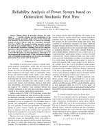
Figure 1: (a) Physical model of fluid flow. (b) Schematic diagram of
embedded surface microchannels (the subscripts of 𝑛𝑠 and 𝑠 refer to
no-slip and slip conditions, resp.).
hydrophobic open microchannels together with biotechnological application areas of open microchannels motivates us
to consider carefully a practical design for controlling the
entropy production of various non-Newtonians in microscale
systems. There have been many theoretical problems developed for entropy generation analysis of boundary layer flow.
However, to the best of our knowledge, no investigation has
been made yet to evaluate EBSM in a non-Newtonian fluid
system. The EBSM technique is recommended here, as a
proper surface shape technique due to valuation of entropy
production in microscale systems. Such innovations can
examine energy efficiency of existing microfluidic systems by
embedding microchannels within permeable surfaces.
2. Mathematical Formulation
2.1. Flow and Heat Transfer Analysis. The flow configuration
is illustrated in Figure 1(a). First, we prepare the flow and
heat transfer mathematical formulation of steady, 2D, laminar
slip boundary layer flow of a power-law non-Newtonian
fluid over continuously permeable moving surface with
constant velocity 𝑈 at prescribed surface temperature in
the presence of viscous dissipation (see Figure 1(a)). After
that, the utilization of the second law of thermodynamics is
focused on EBSM which requires simultaneous modeling of
the slip and no-slip boundary condition along the width of
the micropatterned surface (see Figure 1(b)). It is assumed
that the width of the surface consists of a specific number
of open microchannels and the base sections (𝑚), each of
which has its own width. Moreover, a no-slip condition
4
Mathematical Problems in Engineering
is applied between open microchannels, whereas a slip
condition is applied to the open parallel microchannels.
Thus, in the present micropatterned surface design, based on
EBSM techniques [7, 37, 39–41], the slip boundary condition
is applied inside the open microchannels. Experimental
evidence recommends that, for water flowing through a
microchannel, the surface of which is coated with a 2.3 nm
thick monolayer of hydrophobic octadecyltrichlorosilane, an
apparent hydrodynamic slip is measured just above the solid
surface. This velocity is about 10% of the free-stream velocity
[45].
Based on the assumptions of the problem, non-Newtonian fluid is a continuum and an incompressible fluid.
The positive 𝑦-coordinate is considered normal to the 𝑥coordinate. The corresponding velocity components in the 𝑥
and 𝑦 directions are 𝑢 and V, respectively. 𝑥 is the coordinate
along the plate measured from the leading edge. The positive
𝑦-coordinate is measured perpendicular to the 𝑥-coordinate
in the outward direction towards the fluid. The corresponding
velocity components in the 𝑥 and 𝑦 directions are denoted as
𝑢 and V, respectively. A permeable surface is considered here
at prescribed surface temperature (PST), 𝑇wall given by [7]
𝑦 = 0,
𝑘
𝑇 = 𝑇wall (= 𝑇∞ + 𝐴𝑥 ) ,
𝑄0 (𝑇 − 𝑇∞ ) , 𝑇 ≥ 𝑇∞
0
𝑇 < 0,
(3)
where 𝑄0 is the heat generation/absorption coefficient. The
continuity, momentum, and energy equations for power-law
fluid in Cartesian coordinates 𝑥 and 𝑦 are
𝑢
(4)
𝜕𝑢 𝜇 𝜕 𝜕𝑢 𝑛−1 𝜕𝑢
𝜕𝑢
+V
=
(
),
𝑢
𝜕𝑥
𝜕𝑦 𝜌 𝜕𝑦 𝜕𝑦 𝜕𝑦
(5)
𝜇 𝜕𝑢 𝑛+1 𝑄0 (𝑇 − 𝑇∞ )
𝜕𝑇
𝜕𝑇
𝜕2 𝑇
,
+V
=𝛼 2 +
+
𝜕𝑥
𝜕𝑦
𝜕𝑦
𝜌𝑐𝑝 𝜕𝑦
𝜌𝑐𝑝
(6)
where 𝑛, 𝜌, 𝛼, and 𝜇 are the power-law index parameter, the
fluid density, the thermal diffusivity, and the consistency
index for non-Newtonian viscosity, respectively. 𝑇 is the
temperature of the fluid and 𝑐𝑝 is the specific heat at constant
pressure. The associated boundary conditions are given by
𝜕𝑢 𝑛−1 𝜕𝑢
𝑦 = 0 ⇒ 𝑢 = 𝑈 + 𝑢𝑠 = 𝑈 + 𝑙1 (
) ,
𝜕𝑦 𝜕𝑦 𝑤
𝑇 = 𝑇𝑤 (= 𝑇∞ + 𝐴𝑥𝑘 )
𝑦 → ∞ ⇒ 𝑢 = 0,
𝜕𝜓
,
𝜕𝑦
V=
𝜕𝜓
𝜕𝑥
(8)
Similarity solution method permits transformation of the
partial differential equations (PDE) associated with the transfer of momentum and thermal energy to ordinary differential
equations (ODE) containing associated parameters of the
problem by using nondimensional parameters. Applying similarity method, the fundamental equations of the boundary
layer are transformed to ordinary differential ones. The
stream function, 𝜓, which is a function of 𝑥 and 𝑦, can
be expressed as a function of 𝑥 and 𝜂, if the similarity
solution exists. The mathematical analysis of the problem
can be simplified by introducing the following dimensionless
coordinates:
𝑓 (𝜂) =
𝜃 (𝜂) =
𝑇 − 𝑇∞
,
𝑇𝑤 − 𝑇∞
𝑢
𝑈
𝜂 = 𝑦(
𝑈2−𝑛
)
]∞ 𝑥
1/(𝑛+1)
𝜓 (𝜂) = (]∞ 𝑥𝑈2𝑛−1 )
𝑓 (𝜂) ,
(9)
where ]∞ is the non-Newtonian kinematic viscosity, 𝑓(𝜂) is
the dimensionless stream function, 𝜃(𝜂) is the dimensionless
temperature of the fluid in the boundary layer region, and 𝜓
is stream function as a function of 𝑥 and 𝜂. By means of above
similarity variables, non-Newtonian fluid velocity adjacent to
the wall can be defined as follows:
𝑛−1
(10)
𝑓 (0) = 1 + 𝐾 (𝑓 (0) 𝑓 (0) ) ,
where 𝐾 is the slip coefficient given by
𝜕𝑢 𝜕V
+
= 0,
𝜕𝑥 𝜕𝑦
V = V𝑤 ,
𝑢=
(2)
where 𝐴 is a constant and 𝑘 is the surface temperature parameter at the prescribed surface temperature (PST)
boundary condition. Besides, the volumetric rate of heat
generation is defined as follows [26, 46, 47]:
𝑄={
where 𝑢𝑠 is the partial slip based on power-law nonNewtonian fluid adjacent to the wall and 𝑙1 is the slip length
having dimension of length. The equation of continuity is
integrated by the introduction of the stream function 𝜓(𝑥, 𝑦).
The stream function satisfies the continuity equation (4) and
is defined by
𝑇 = 𝑇∞ ,
(7)
𝑙
𝑈3
)
𝐾= 1(
𝑈 ]∞ 𝑥
𝑛/(𝑛+1)
.
(11)
The momentum and energy equations and the associated
boundary conditions reduce to the following system of similarity equations:
𝑛−1
𝑛 (𝑛 + 1) 𝑓 𝑓 + 𝑓𝑓 = 0,
𝜃 +
Pr
𝑛+1
𝑓𝜃 + PrEc𝑓 + Pr𝑠𝜃 − Pr𝑘 𝑓 𝜃 = 0.
𝑛+1
(12)
The associated boundary conditions are given by
𝑛−1
{
𝑓 (0) = 1 + 𝐾 (𝑓 (0) 𝑓 (0) )
{
{
𝜂 = 0 ⇒ {𝑓 (0) = 𝑓𝑤
{
{
{𝜃 (0) = 1
𝑓 (∞) = 0
𝜂 → ∞ ⇒ {
𝜃 (∞) = 0,
(13)
Mathematical Problems in Engineering
5
where 𝑠, 𝑓𝑤 , Pr, and Ec show the heat generation/absorption
parameter, the suction/injection parameter, the modified
local non-Newtonian Prandtl number, and the Eckert number, respectively. Accordingly, the involved parameters of the
problem are defined by
𝐾=
𝑙1 𝑈3
(
)
𝑈 ]∞ 𝑥
𝑈 𝑈2−𝑛
Pr =
(
)
𝛼𝑥 ]∞ 𝑥
𝑛/(𝑛+1)
,
𝑓𝑤 =
,
Ec =
−2/(𝑛+1)
− (𝑛 + 1) 𝑥𝑛/(𝑛+1) V𝑤
1/(𝑛+1)
(]∞ 𝑈2𝑛−1 )
𝑈2
,
𝐴𝑥𝑘 𝑐𝑝
𝑠=
𝑄0 𝑥
.
𝑈𝜌𝑐𝑝
(14)
Suction/injection parameter 𝑓𝑤 determines the transpiration
rate along the surface with 𝑓𝑤 > 0 for suction, 𝑓𝑤 < 0
for injection, and 𝑓𝑤 = 0 corresponding to an impermeable
surface. The one-way coupled equations (12) are solved
numerically by using the explicit Runge-Kutta (4, 5) formula,
the Dormand-Prince pair, and shooting method, subject to
the boundary conditions (13). Thus, the local skin friction
coefficient and the local Nusselt number exhibit dependence
on the involved parameters of the problem as follows:
2𝜏
𝑛−1
𝐶𝑓𝑥 = − 𝑤2 = −2Re−1/(𝑛+1) 𝑓 (0) 𝑓 (0) ,
𝜌𝑈
−𝑥 (𝜕𝑇/𝜕𝑦)𝑦=0
𝑁𝑢𝑥 =
= Re1/(𝑛+1) 𝜃 (0) ,
𝑇𝑤 − 𝑇∞
(15)
is applied over the local rate of entropy generation adjacent
to the wall. The cross-stream (𝑧) dependence arises from
interspersed no-slip (subscript 𝑛𝑠) and slip-flow (subscript
𝑠) solutions of the boundary layer equations. Therefore, the
integration over the width of the surface from 0 ≤ 𝑧 ≤ 𝑊
consists of 𝑚 separate integrations over each microchannel
surface width, 0 ≤ 𝑧 ≤ 𝑊𝑠 + 2𝑑, as well as the remaining
no-slip portion of the plate, which is interspersed between
these microchannels and covers a range of 0 ≤ 𝑧 ≤ 𝑊 − 𝑚𝑊𝑠
(see Figure 1(b)). Thus, by performing the integrations and
assuming an equal number of microchannels and no-slip gaps
interspersed between those microchannels (see Figure 1(b)),
it can be shown that
𝑆𝑔 = 𝑆𝑇 + 𝑆𝐹 ,
where
𝑚(𝑊𝑠 +2𝑑)
𝑆𝑇 = ∫
0
𝑆𝐹
=∫
𝑆𝑔 =
𝜇 𝜕𝑢 𝑛+1
𝑘∞
𝜕𝑇 2
𝜕𝑇 2
[(
+
(
]
+
)
)
2
𝑇∞
𝜕𝑥
𝜕𝑦
𝑇∞ 𝜕𝑦
𝑊−𝑚𝑊𝑠
𝑆𝑇,slip
𝑑𝑧 + ∫
0
𝑚(𝑊𝑠 +2𝑑)
0
𝑆𝐹,slip
𝑑𝑧
𝑊−𝑚𝑊𝑠
+∫
0
𝑆𝑇,no-slip
𝑑𝑧,
(18)
𝑆𝐹,no-slip
𝑑𝑧.
Moreover, the dimensionless local entropy generation rate
is defined as a ratio of the present local entropy generation
,
rate 𝑆𝑔 and a characteristic entropy generation rate 𝑆𝑔0
called entropy generation number 𝑁𝑠 . Here, the characteristic
entropy generation rate, based on the width of the surface, is
defined as
where Re = 𝜌𝑈2−𝑛 𝑥𝑛 /𝜇 refers to the local Reynolds number.
2.2. Entropy Generation Analysis. Entropy generation analysis concerned with the power-law non-Newtonian fluid
flow over open parallel microchannels embedded within a
continuously permeable moving surface at prescribed surface
temperature in the presence of viscous dissipation. Thus, heat
transfer (𝑆𝑇 ) and friction irreversibilities (𝑆𝐹 ) are included
within the local volumetric rate of entropy generation. The
rate of entropy generation will be obtained based on the
previous solutions of the boundary layer for fluid velocity
and temperature. According to Woods [48], Khan and Gorla
[49], and Hung [50], the local volumetric rate of entropy
generation for power-law non-Newtonian flow is given by
(17)
𝑆𝑔0 =
𝑘∞ Δ𝑇2 𝑊
,
2
𝐿2 𝑇∞
(19)
where 𝐿 is characteristic length scale. In addition, the
nondimensional geometric parameters are defined as (see
Figure 1(b))
𝜆=
𝑊𝑠 + 2𝑑
,
𝑊
𝜍=
𝑑
.
𝑊
Consequently, the entropy generation number is expressed as
𝑁𝑠 =
=
𝑆𝑔
𝑆𝑔0
𝑘2 2
𝜃 (0) [𝑚𝜆]
𝑋2 𝑠
(16)
+
𝑘2 2
𝜃 (0) [1 + 2𝑚𝜍 − 𝑚𝜆]
𝑋2 𝑛𝑠
where 𝑘∞ is thermal conductivity. In the present work, the
integration of the above local entropy generation is done
only along the width of the surface (𝑧-direction) due to considering the impact of embedded microchannels within the
permeable surface. This type of integration leads to study the
effects of combined slip/no-slip conditions on local entropy
generation rates. With the intention of considering the effect
of the embedded open parallel microchannels with-in a
permeable surface, integration over the width of the surface
+
Re(2/(𝑛+1)) 2
𝜃𝑠 (0) [𝑚𝜆]
𝑋2
+
Re(2/(𝑛+1)) 2
𝜃𝑛𝑠 (0) [1 + 2𝑚𝜍 − 𝑚𝜆]
𝑋2
+
Br Re (𝑛+1)
𝑓 (0)
[𝑚𝜆]
Ω 𝑋2 𝑠
+
Br Re (𝑛+1)
𝑓 (0)
[1 + 2𝑚𝜍 − 𝑚𝜆] ,
Ω 𝑋2 𝑠
= 𝑆𝑇 + 𝑆𝐹 ,
(20)
(21)
Mathematical Problems in Engineering
1
1
0.9
0.9
0.8
0.8
0.7
0.7
0.6
0.6
𝜃(𝜂)
f (𝜂)
6
0.5
0.5
0.4
0.4
0.3
0.3
0.2
0.2
0.1
0.1
0
0
2
4
6
𝜂
K = 0.0
K = 0.2
8
10
12
0
0
0.5
1
1.5
𝜂
K = 0.0
K = 0.2
K = 0.5
K=1
(a)
2
2.5
3
K = 0.5
K=1
(b)
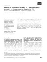
Figure 2: (a) Distribution of velocity as function of 𝜂 for various values of 𝐾 when 𝑓𝑤 = 0.2, 𝑛 = 0.8. (b) Distribution of temperature as
function of 𝜂 for various values of 𝐾 when 𝑓𝑤 = 0.2, 𝑛 = 0.8, 𝑠 = 0.1, Ec = 0.1, 𝑘 = 0.1, and Pr = 5.
where 𝑋, Re, Br, and Ω are, respectively, the nondimensional
surface length, the Reynolds number, the Brinkman number,
and the dimensionless temperature difference. These parameters are given by the following relationships:
Br =
𝜇𝑈𝑛+1
,
𝑥𝑛−1 𝑘∞ Δ𝑇
Re =
𝑥
𝑋= ,
𝐿
Δ𝑇
.
Ω=
𝑇∞
𝑈2−𝑛 𝑥𝑛
,
]∞
(22)
The Bejan number is defined as the ratio of heat transfer irreversibility to total irreversibility due to heat transfer and fluid
friction for the power-law non-Newtonian boundary layer
flow. Bejan number is given by
Be =
Heat transfer irreversibility
1
=
,
Entropy generation number 1 + Φ
(23)
where Φ is the irreversibility distribution ratio which is given
by
Φ=
Fluid friction irreversibility
.
Heat transfer irreversibility
(24)
As the Bejan number ranges from 0 to 1, it approaches zero
when the entropy generation due to the combined effects
of fluid friction and magnetic field is dominant. Similarly,
Be > 0.5 indicates that the irreversibility due to heat transfer
dominates, with Be = 1 as the limit at which the irreversibility
is solely due to heat transfer. Consequently, 0 ≤ Φ ≤ 1
indicates that the irreversibility is primarily due to the heat
transfer irreversibility, whereas for Φ > 1 it is due to the fluid
friction irreversibility. The entropy generation number, 𝑁𝑠 in
(21) together with Bejan number in (23) will be used for the
evaluation of the present study.
3. Results and Discussion
The nonlinear governing partial differential equations are
converted into a set of nonlinear ordinary differential ones
through similarity transformations technique and then
solved numerically by the Dormand-Prince pair and shooting
method. The computed numerical results are shown graphically in Figures 2–14. As a test of the accuracy of the solution,
a comparison between the present code results and those
obtained previously is presented. Although the main focus of
this paper is entropy generation, graphical presentations of
local skin friction and local Nusselt number are required in
order to understand the mechanisms of entropy generation
along micropatterned surface. Therefore, in the first step, the
effects of involved parameters of the problem on flow and
heat transfer are displayed. After that, the entropy generation
numbers, as well as the Bejan number, for various values of
the involved parameters are evaluated.
3.1. Effects on Flow and Heat Transfer. In order to verify
the accuracy of the present results, our results are compared
for the local skin-friction coefficient and the local Nusselt
number to those of previous studies for some special cases.
Table 1 proves that the present numerical results agree well
with those obtained by Sakiadis [47], Fox et al. [51], Chen
[52], Jacobi [53], and Mahmoud [26] for special case of 𝑛 = 1,
𝐾 = 0, 𝑀 = 0, 𝑓𝑤 = 0, Pr = 0.7, Ec = 0, 𝑠 = 0, and 𝑘 = 0.0.
Moreover, Table 2 indicates another comparison of our work
(𝑛−1)
and
for the local skin friction coefficient, −𝑓 (0)|𝑓 (0)|
temperature gradient at the wall |𝜃 (0)|, respectively, with
those obtained by Mahmoud [26] at special case of constant
surface temperature (𝑘 = 0). Our results are found to be in
excellent agreement with previous results as seen from the
tabulated results.
Figure 2(a) presents the velocity profiles 𝑓 (𝜂) as function
of 𝜂 for various values of slip coefficient 𝐾 when 𝑓𝑤 = 0.2,
Mathematical Problems in Engineering
7
Table 1: Comparison of the |𝑓 (0)| and |𝜃 (0)| between the present results and those obtained previously for special case of 𝑛 = 1, 𝐾 = 0,
𝑓𝑤 = 0.0, Pr = 0.7, Ec = 0.0, 𝑠 = 0.0, and 𝑘 = 0.0.
Fox et al. [51]
0.4437
Mahmoud [26]
0.44375
Present
0.44375
1
1
0.9
0.9
0.8
0.8
0.7
0.7
0.6
0.6
𝜃(𝜂)
f (𝜂)
Sakiadis [47]
0.44375
|𝑓 (0)|
Chen [52]
0.4438
0.5
0.4
0.3
0.3
0.2
0.2
0.1
0.1
0
2
4
6
8
10
12
14
0
0
0.5
1
1.5
𝜂
𝜂
n=1
n = 1.2
n = 0.4
n = 0.8
2
2.5
3
n=1
n = 1.2
n = 0.4
n = 0.8
(a)
Present
0.34925
0.5
0.4
0
Jacobi [53]
0.3492
|𝜃 (0)|
Chen [52]
Mahmoud [26]
0.34925
0.34925
(b)
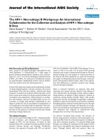
Figure 3: (a) Distribution of velocity as function of 𝜂 for various values of 𝑛 when 𝑓𝑤 = 0.2, 𝐾 = 0.1. (b) Distribution of temperature as
function of 𝜂 for various values of 𝑛 when 𝑓𝑤 = 0.2, 𝐾 = 0.1, 𝑠 = 0.1, Ec = 0.1, 𝑘 = 0.1, and Pr = 5.
𝑛−1
and
Table 2: Comparison of the skin friction −𝑓 (0)|𝑓 (0)|
|𝜃 (0)| between the present results and those obtained previously for
special case of 𝑛 = 0.8, 𝐾 = 0.1, Pr = 10, Ec = 0.1, 𝑠 = 0.1, and
𝑘 = 0.0.
Mahmoud [26]
𝑛−1
|𝜃 (0)|
−𝑓 (0)|𝑓 (0)|
−0.5
0.3619
0.0303
−0.2
0.4339
0.6604
0.0
0.4865
1.2914
0.2
0.5425
2.0490
0.5
0.6326
3.3460
𝑓𝑤
Present results
𝑛−1
−𝑓 (0)|𝑓 (0)|
|𝜃 (0)|
0.3619
0.0303
0.4339
0.6604
0.4865
1.2914
0.5425
2.0490
0.6326
3.3460
𝑛 = 0.8. The dominating nature of the slip on the boundary
layer flow is clear from this figure. When partial slip occurs,
the flow velocity near the surface is no longer equal to the
velocity of moving surface. One can see that in the presence
of slip, as 𝐾 increases, 𝑓 (𝜂) near to the wall is decreased
and then increases away from it resulting an intersection in
the velocity profile. Physically, the presence of velocity slip
on the moving surface within stationary fluid has tendency
to decrease fluid velocity adjacent to the wall, causing the
hydrodynamic boundary layer thickness to increase. In all
cases the velocity vanishes at some large distance from the
surface. The effect of slip coefficient 𝐾 on temperature profile
is illustrated in Figure 2(b) when 𝑓𝑤 = 0.2, 𝑛 = 0.8, 𝑠 = 0.1,
Ec = 0.1, 𝑘 = 0.1, and Pr = 5. It can be observed that an
increase with slip coefficient tends to enhance temperature
in the boundary layer. Moreover, decreasing the values of the
slip coefficient leads to thinning of the thermal boundary
layer thickness.
Figures 3(a) and 3(b) illustrate the influence of the powerlaw index parameter 𝑛, from shear-thinning fluids (𝑛 = 0.4)
to shear-thickening fluids (𝑛 = 1.2) on nondimensional
velocity and temperature profiles, respectively. For nonNewtonians, the slope of the shear stress versus shear rate
curve will not be constant as we change the shear rate. As
explained, when the viscosity decreases with increasing shear
rate, we call the fluid shear thinning. Having a power-law
index 𝑛 < 1 is referred as a shear-thinning fluid. Thus, a
reduction in the shear layer (when compared with Newtonian
fluid flow) is a characteristic feature of non-Newtonian fluids
when 𝑛 < 1. One explanation of shear thinning is that asymmetric particles are progressively aligned with streamlines, an
alignment that responds nearly instantaneously to changes in
the imposed shear; after complete alignment at high shear
the apparent viscosity becomes constant [54]. In the opposite
case where the viscosity increases as the fluid is subjected
to a higher shear rate, the fluid is called shear thickening
having an index 𝑛 > 1 [55]. These figures indicate that the
velocity profiles decrease with the increase of 𝑛 in velocity
boundary layer but this consequence is not very noticeable
adjacent to the wall (see Figure 3(a)). One can see that, in
8
Mathematical Problems in Engineering
1
0.65
0.6
Cfx /(2Re(−1/(n+1)
)
x
0.95
f (0)
0.9
0.85
0.8
0.75
0.55
0.5
0.45
0.4
0.35
0
0.05
0.1
0.15
0.2
0.25
0.3
0.35
0.4
0.45
0.5
0.3
0
0.1
0.2
fw
fw
fw
fw
=
=
=
=
−0.3
−0.2
−0.1
0.0
0.3
0.4
0.5
K
K
fw = 0.1
fw = 0.2
fw = 0.3
(a)
fw
fw
fw
fw
=
=
=
=
−0.3
−0.2
−0.1
0.0
fw = 0.1
fw = 0.2
fw = 0.3
(b)
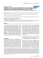
Figure 4: Variation of the (a) 𝑓 (0) and (b) skin friction as function of 𝐾 for various values of 𝑓𝑤 when 𝑛 = 0.8.
the presence of velocity slip, as 𝑛 increases, nondimensional
velocity 𝑓 (𝜂) increases near to the wall and then decreases
away from it resulting an intersection in the velocity profile.
Consequently, an increase of 𝑛 tends to reduce boundary
layer thickness; that is, the thickness is much large for shear
thinning (pseudoplastic) fluids (0 < 𝑛 < 1) than that of
Newtonians (𝑛 = 1) and shear thickening (dilatant) fluids
(1 < 𝑛 < 2). It is noted, the temperature profile enhances
as 𝑛 increases and the power-law index 𝑛 has a tendency to
increase the thickness of the thermal boundary layer.
Figures 4(a) and 4(b) display variation of the 𝑓 (0)
and local skin friction coefficient respectively, versus 𝐾 for
various values of 𝑓𝑤 when 𝑛 = 0.8. It is interesting to
note that the slip coefficient can successfully decrease local
skin friction coefficient along surface. Besides, it is worth
mentioning to note that the effect of velocity slip on both
𝑓 (0) and skin friction is more significant in the suction
case (𝑓𝑤 > 0), than injection (𝑓𝑤 < 0), specially at high
suction parameter since gradient of the 𝑓 (0) versus 𝐾 is
much higher in the presence of suction. Furthermore, the
suction/injection parameter has been potential to control
velocity adjacent to the wall in the slip boundary condition
problems, specially, at higher values of 𝐾. An increase of
suction decreases nondimensional velocity at the wall while
injection depicts opposite effects. Besides, injection fluid into
the hydrodynamic boundary layer decreases the local skinfriction coefficient, while increasing the suction parameter
enhances the local skin-friction coefficient.
The effect of the power law index parameter 𝑛 and 𝐾 on
(a) fluid velocity adjacent to the wall 𝑓 (0) and (b) the local
skin friction coefficientis illustrated in Figures 5(a) and 5(b),
respectively. An increase of the index parameter 𝑛 tends to
increase the fluid velocity adjacent to the wall and thereby
to reduce velocity gradient at the wall. The skin friction
coefficient is much larger for shear thinning (pseudoplastic)
fluids (0 < 𝑛 < 1) than that of shear thickening (dilatant)
fluids (1 < 𝑛 < 2), as clearly seen from Figure 5(b). The gradient of the 𝑓 (0) versus 𝐾 is much higher in the shear
thinning fluids. Thus, it is interesting to note that the effect
of partial slip on both 𝑓 (0) and skin friction is significant
in shear thinning fluid (𝑛 < 1) then shear thickening
fluid (𝑛 > 1). The reason goes back to the power-law
index of non-Newtonian fluids based on the consistency
index for non-Newtonian viscosity equation (10). Physically,
for pseudoplastic non-Newtonian fluids (𝑛 < 1) viscosity
decreases as shear rate increases (shear rate thinning). On
the other hand, for dilatant (𝑛 > 1) viscosity increases as
shear rate increases (shear rate thickening). Consequently, the
effect of increasing values of power-law index parameter 𝑛 is
to increase the fluid velocity adjacent to the wall while leading
to decrease the skin friction coefficient. The computed value
of Figure 5(b) can be compared here for special case (𝑛 =
0.8, 𝐾 = 0.1) with that obtained by Mahmoud [26], where
𝑛−1
is equal to 0.5425 and it exhibits perfect
−𝑓 (0)|𝑓 (0)|
agreement.
The effect of the surface temperature parameter 𝑘 on
local Nusselt number is shown in Figure 6. It is seen that
local Nusselt number increases with the increase in surface
temperature parameter. It is noted that the heat transfer rate
increases with the increase of Prandtl number for fixed values
of 𝐾 and 𝑘 . It is interesting to note that what we can do to
reach a high heat transfer rate is to use a non-Newtonian fluid
with low power-law index parameter 𝑛. This is possible and
suitable way to attain a high heat transfer rate (see Figure 7).
In general the results show a decrease in the Nusselt numbers
with an increase in the power law index parameter 𝑛 where
the Nusselt number is higher for shear thinning (pseudo
plastic) fluids (0 < 𝑛 < 1) than that of shear thickening
9
1
1
0.95
0.9
0.9
0.8
Cfx /(2Re(−1/(n+1)
)
x
f (0)
Mathematical Problems in Engineering
0.85
0.8
0.75
0.6
0.5
0.4
0.7
0.65
K = 0.1
(n−1)
−f (0)|f (0)|
= 0.5425
0.7
0
0.05
0.1
0.15
0.2
0.25
0.3
0.35
0.4
0.45
0.5
0.3
0
0.05
0.1
0.15
0.2
0.25
n=1
n = 1.2
n = 0.4
n = 0.6
n = 0.8
0.3
0.35
0.4
0.45
0.5
K
K
n=1
n = 1.2
n = 0.4
n = 0.6
n = 0.8
(a)
(b)
Figure 5: Variation of (a) 𝑓 (0) and (b) skin friction versus 𝐾 for various values of 𝑛 when 𝑓𝑤 = 0.2.
2.8
1.7
1.6
2.6
1.5
Nu x /(Re(1/(n+1)
)
x
2.4
Nu x /(Re(1/(n+1)
)
x
2.2
2
K = 0.1
−𝜃 (0) = 2.049
1.8
1.4
1.3
1.2
1.1
1
1.6
0.9
1.4
0.05
0.1
n = 0.4
n = 0.6
n = 0.8
1.2
1
0
0
0.1
0.2
0.3
0.4
0.5
K
k
k
k
k
=
=
=
=
0.0 Pr = 5
0.1
0.2
0.3
k = 0.0 Pr = 10
k = 0.1
k = 0.2
k = 0.3
Figure 6: Local Nusselt number as function of 𝐾 for various values
of 𝑘 and Pr when 𝑓𝑤 = 0.2, 𝑠 = 0.1, 𝑛 = 0.8, and Ec = 0.1.
(dilatant) fluids (1 < 𝑛 < 2). The variation of local Nusselt
number as function of 𝐾 for various values of 𝑓𝑤 when
𝑛 = 0.8, 𝑠 = 0.1, 𝑘 = 0.1, Pr = 5, and Ec = 0.1 is illustrated
in Figure 8. For a fixed value of 𝐾 increasing suction results
in an increase in the Nusselt number. Besides, the impact of
increasing injection is seen to reduce the heat transfer, similar
0.15
0.2
0.25
K
0.3
0.35
0.4
0.45
0.5
n=1
n = 1.2
Figure 7: Local Nusselt number as function of 𝐾 for various values
of 𝑛 when 𝑓𝑤 = 0.2, 𝑠 = 0.1, 𝑘 = 0.1, Pr = 5, and Ec = 0.1.
to the case of increasing slip coefficient. Figure 9 depicts the
effect of heat generation (𝑠 > 0) or absorption parameter
(𝑠 < 0) on local Nusselt number. The same consequence
for the slip coefficient is illustrated; as 𝐾 decreases the heat
transfer rate is increased. In addition, it is noted that an
increase in heat generation parameter tends to decrease heat
transfer rate whereas heat absorption acts in the opposite way.
Physically, the reason is that the heat generation presence will
enhance the fluid temperature adjacent to the wall and thus
temperature gradient at the surface decreases, thus decreasing
the heat transfer at the surface. But as the heat absorption
increases, the local Nusselt number increases. This is because
10
Mathematical Problems in Engineering
increasing the heat absorption generates to layer of cold fluid
near to the heated surface.
1.8
1.6
Nu x /(Re(1/(n+1)
)
x
1.4
1.2
1
0.8
0.6
0.4
0
0.1
0.2
0.3
0.4
0.5
K
fw
fw
fw
fw
=
=
=
=
−0.3
−0.2
−0.1
0.0
fw = 0.1
fw = 0.2
fw = 0.3
Figure 8: Local Nusselt number as function of 𝐾 for various values
of 𝑓𝑤 when 𝑛 = 0.8, 𝑠 = 0.1, 𝑘 = 0.1, Pr = 5, and Ec = 0.1.
0.8
1
Nu x /(Re(1/(n+1)
)
x
1.2
1.4
1.6
1.8
2
2.2
0.5
0.4
0.3
0.2
0.1
0
K
s=
s=
s=
s=
0.0
0.1
0.2
0.3
s = −0.1
s = −0.2
s = −0.3
Figure 9: Local Nusselt number as function of 𝐾 for various values
of 𝑠 when 𝑛 = 0.8, 𝑓𝑤 = 0.2, 𝑘 = 0.1, Pr = 5, and Ec = 0.1.
3.2. Effects on Entropy Generation Analysis. The following
section presents the results for entropy generation analysis
of power-law fluid flow over open parallel microchannels
embedded within a continuously permeable moving surface
at PST in the presence of heat generation/absorption and
viscous dissipation. The entropy generation number as a
function of the change in the number of embedded open
parallel microchannels for various values of power-law index
parameters, 𝑛 = 0.8, 𝑛 = 1, and 𝑛 = 1.2, is illustrated
in Figures 10(a), 10(b), and 10(c), respectively. Here, it is
demonstrated that the design of embedded open parallel
microchannels yields an interesting result with respect to
reduction of the entropy generation of convective heat transfer over moving surface. We know that the slip inside the
open microchannels is considered, particularly in cases where
a hydrophobic microchannel surface exists. First of all, it
should be remembered that an increase in the slip coefficient
tends to decrease both heat transfer and friction losses along a
stretching surface within stationary fluid. On the other hand,
the entropy generation number 𝑁𝑠 is comprised of friction
and heat transfer irreversibilities. Thus, the entropy generation number decreases by increasing the slip coefficient in all
three cases of shear thinning (pseudoplastic) fluids when 𝑛 =
0.8 (see Figure 10(a)), Newtonian fluid when 𝑛 = 1 (see Figure 10(b)), and shear thickening (dilatant) fluids when 𝑛 = 1.2
(see Figure 10(c)). The intersection point between the graphs
in all three figures determines different trends resulting
from the larger slip coefficients, as compared to the smaller
slip coefficients (before the intersection point). There is an
intersection point within the graphs named as “critical point.”
Afterward, the influence of the slip coefficient is considerable
on the system and the region is called “effectual region.” As
a greater surface area results in an increased surface friction
due to a larger number of embedded microchannels, when
the slip coefficient inside the microchannels is not sufficient,
an increase in the number of microchannels tends to increase
the entropy generation number, due to added surface friction.
This phenomenon is much more pronounced when the values
of slip coefficient are less than critical point. Consequently,
extra effort and cost associated with micromachining the
surface to achieve a desired embedded microchannel surface
cannot be warranted. However, for high values of the slip
coefficient (after the critical point, inside effectual region),
an increase in the number of open parallel microchannels
can effectively decrease the entropy generation number.
Consequently, it is necessary to consider the projected values
of the slip coefficients inside the microchannels required in
order to establish an appropriate design of the open parallel
microchannels embedded within the moving surface due
to a reduction in the exergy losses. This can be effectively
achieved by considering hydrophobic open microchannels
with high slip coefficients. It is interesting to note that
the entropy generation number is lower for higher powerlaw index parameters, whereby the presence of the shear
thinning (pseudoplastic) fluids creates entropy along the
Mathematical Problems in Engineering
11
×104
3.13
3.12
3.11
3.1
Ns
3.09
3.08
3.07
3.06
3.05
K = 0.63
3.04
3.03
0
0.1
0.2
0.3
0.4
m = 0.0 n = 0.8
m = 100
m = 200
0.5
K
0.6
0.7
0.8
0.9
1
m = 500
m = 700
m = 1000
(a)
×104
1.505
×104
2.11
1.5
2.1
1.495
1.49
2.08
Ns
Ns
2.09
2.07
1.48
1.475
1.47
2.06
2.05
1.485
K = 0.65
0
0.1
0.2
0.3
0.4
m = 0.0 n = 1
m = 100
m = 200
0.5
K
0.6
0.7
1.465
0.8
0.9
m = 500
m = 700
m = 1000
(b)
1
1.46
K = 0.66
0
0.1
0.2
0.3
0.4
0.5
0.6
0.7
0.8
0.9
1
K
m = 0.0 n = 1.2
m = 100
m = 200
m = 500
m = 700
m = 1000
(c)
Figure 10: 𝑁𝑠 as a function of 𝐾 for various values of 𝑚 and (a) 𝑛 = 0.8. (b) 𝑛 = 1. (c) 𝑛 = 1.2 when 𝑓𝑤 = 0.2, Pr = 5, Ec = 0.1, 𝑘 = 0.1,
𝑠 = 0.1, 𝑋 = 0.03, BrΩ−1 = 0.1, Re = 10, 𝜁 = 0.00001, and 𝜆 = 0.0001.
surface, with a noticeable opposite effect resulting from shear
thickening (dilatant) fluids. Another interesting aspect of the
problem is that the critical point moves slightly rightward for
higher index parameters. This means that wider range of slip
coefficients can be beneficial for the shear thinning than shear
thickening fluids.
Effects of number of microchannels on Bejan number for
various values of power-law index parameter at 𝑛 = 0.8, 𝑛 = 1,
and 𝑛 = 1.2 are illustrated in Figures 11(a), 11(b), and 11(c),
respectively. It indicates that an increase in the number of
microchannels causes an increase of the Bejan number. At
high 𝑚, the Bejan number is high due to a small irreversibility
distribution ratio Φ where the temperature irreversibilities
are prominent. An increase in the number of microchannels
can verify the desirable circumstances required for our system in order to reduce entropy generation where it is possible
to efficiently take advantage of slip flow boundary conditions.
As explained before, partial slip decreases both friction and
heat transfer irreversibilities. However it is obvious from the
figure that the reduction rate of friction irreversibilities is
much higher compared with heat transfer irreversibilities
since the Bejan number increases by 𝐾. It is also noted that
12
Mathematical Problems in Engineering
0.987
0.9869
0.9897
0.9868
0.9867
0.9895
Be
Be
0.9896
0.9866
0.9865
0.9894
0.9864
0.9893
0.9892
0.9863
0
0.1
0.2
0.3
0.4
0.5
K
m = 0.0 n = 0.8
m = 100
m = 200
0.6
0.7
0.8
0.9
0.9862
1
0
0.1
0.2
0.3
0.4
m = 0.0 n = 1
m = 100
m = 200
m = 500
m = 700
m = 1000
(a)
0.5
K
0.6
0.7
0.8
0.9
1
m = 500
m = 700
m = 1000
(b)
0.9837
0.9836
0.9835
Be
0.9834
0.9833
0.9832
0.9831
0.983
0.9829
0
0.1
0.2
0.3
0.4
m = 0.0 n = 1.2
m = 100
m = 200
0.5
K
0.6
0.7
0.8
0.9
1
m = 500
m = 700
m = 1000
(c)
Figure 11: Bejan number versus 𝐾 for various values of 𝑚 and (a) 𝑛 = 0.8. (b) 𝑛 = 1. (c) 𝑛 = 1.2 when 𝑓𝑤 = 0.2, Pr = 5, Ec = 0.1, 𝑘 = 0.1,
𝑠 = 0.1, 𝑋 = 0.03, BrΩ−1 = 0.1, Re = 10, 𝜁 = 0.00001, and 𝜆 = 0.0001.
an increase in 𝑛 accompanies a slightly reduction in the Bejan
number. This is because of the index parameter influences on
heat transfer rate which shows a decreasing effect.
Figure 12(a) shows change of the entropy generation
number with varying surface nondimensional geometric
parameters and the slip coefficient. The entropy generation
number shows an increase at higher microchannel depths,
whereas it decreases at higher microchannel widths. This suggests that an increase in the width of the microchannels tends
to enhance the slip effects along the width of the surface,
causing the entropy generation number to decrease. The effect
of the nondimensional geometric parameters on the Bejan
number is illustrated in Figure 12(b), which it increases with
the increase in 𝜆. It indicates that an increase in the width
of the microchannels decreases the irreversibility distribution ratio with the increase of heat transfer irreversibilities.
Further, it is also noted that the effect of microchannel depth
on Bejan number could be considered insignificant compared
with the microchannel width.
The influence of the Eckert number on 𝑁𝑠 and Bejan
number is shown in Figures 13(a) and 13(b), respectively,
where it can be noted that an increase in the Ec results in
a decrease in the both 𝑁𝑠 and Be as the heat transfer irreversibility decreases. Figures 14(a) and 14(b) display the effect
of the suction/injection parameter on the entropy generation
number and Bejan number, respectively, for various values
Mathematical Problems in Engineering
13
×104
3.08
3.075
0.9893
3.07
3.06
Be
Ns
3.065
3.055
0.9892
3.05
3.045
3.04
3.035
0
0.1
0.2
0.3
0.4
0.5
K
0.6
0.7
0.8
0.9
1
0.9891
0
𝜆 = 0.0002 𝜁 = 0.00001
𝜆 = 0.0003 𝜁 = 0.00001
𝜆 = 0.0001 𝜁 = 0.00001
𝜆 = 0.0001 𝜁 = 0.00002
𝜆 = 0.0001 𝜁 = 0.00003
0.1
0.2
0.3
0.4
0.5
K
0.7
0.8
0.9
1
𝜆 = 0.0002 𝜁 = 0.00001
𝜆 = 0.0003 𝜁 = 0.00001
𝜆 = 0.0001 𝜁 = 0.00001
𝜆 = 0.0001 𝜁 = 0.00002
𝜆 = 0.0001 𝜁 = 0.00003
(a)
0.6
(b)
Figure 12: (a) 𝑁𝑠 as a function of 𝐾 for various values of 𝜁 and 𝜆 when 𝑛 = 0.8, 𝑓𝑤 = 0.2, Pr = 5, Ec = 0.1, 𝑘 = 0.1, 𝑠 = 0.1, 𝑚 = 100,
𝑋 = 0.03, BrΩ−1 = 0.1, and Re = 10. (b) Bejan number as a function of 𝐾 for various values of 𝜁 and 𝜆 when 𝑛 = 0.8, 𝑓𝑤 = 0.2, Pr = 5,
Ec = 0.1, 𝑘 = 0.1, 𝑠 = 0.1, 𝑚 = 100, 𝑋 = 0.03, BrΩ−1 = 0.1, and Re = 10.
×104
6
0.994
5.5
0.992
5
4.5
0.99
Ns
Be
4
0.988
3.5
3
0.986
2.5
0.984
2
1.5
0
0.1
0.2
0.3
0.4
0.5
0.6
0.7
0.982
0
0.2
0.4
Ec =
Ec =
Ec =
Ec =
Ec =
Ec =
Ec =
Ec =
Ec =
0.2 n = 1
0.1
0.0
0.2 n = 0.8
0.1
(a)
0.6
0.8
1
K
K
0.0
0.2 n = 0.6
0.1
0.0
Ec =
Ec =
Ec =
Ec =
Ec =
0.2 n = 1
0.1
0.0
0.2 n = 0.8
0.1
Ec =
Ec =
Ec =
Ec =
0.0
0.2 n = 0.6
0.1
0.0
(b)
Figure 13: (a) 𝑁𝑠 as a function of 𝐾 for various values of Ec and 𝑛 when 𝑓𝑤 = 0.2, Pr = 5, 𝑘 = 0.1, 𝑠 = 0.1, 𝑋 = 0.03, 𝑚 = 100, BrΩ−1 = 0.1,
Re = 10, 𝜁 = 0.00001, and 𝜆 = 0.0001. (b) Bejan number as a function of 𝐾 for various values of Ec and 𝑛 when 𝑛 = 0.8, 𝑓𝑤 = 0.2, Pr = 5,
𝑘 = 0.1, 𝑠 = 0.1, 𝑋 = 0.03, 𝑚 = 100, BrΩ−1 = 0.1, Re = 10, 𝜁 = 0.00001, and 𝜆 = 0.0001.
14
Mathematical Problems in Engineering
×104
5
0.994
4.5
0.992
4
0.99
3.5
0.988
Be
Ns
3
0.986
2.5
0.984
2
0.982
1.5
0.98
1
0.5
0
0.1
0.2
0.3
0.4
0.5
0.6
0.7
0.978
0
0.1
0.2
0.3
K
fw
fw
fw
fw
=
=
=
=
fw
fw
fw
fw
−0.1 n = 1
0.0
0.1
0.2
0.4
0.5
0.6
0.7
K
=
=
=
=
−0.1 n = 0.6
0.0
0.1
0.2
fw
fw
fw
fw
(a)
=
=
=
=
fw
fw
fw
fw
−0.1 n = 1
0.0
0.1
0.2
=
=
=
=
−0.1 n = 0.6
0.0
0.1
0.2
(b)
Figure 14: (a) 𝑁𝑠 as a function of 𝐾 for various values of 𝑓𝑤 and 𝑛 when Pr = 5, Ec = 0.1, 𝑘 = 0.1, 𝑠 = 0.1, 𝑋 = 0.03, 𝑚 = 100, BrΩ−1 = 0.1,
Re = 10, 𝜁 = 0.00001, and 𝜆 = 0.0001. (b) Bejan number as a function of 𝐾 for various values of 𝑓𝑤 and 𝑛 when Pr = 5, Ec = 0.1, 𝑘 = 0.1,
𝑠 = 0.1, 𝑋 = 0.03, 𝑚 = 100, BrΩ−1 = 0.1, Re = 10, 𝜁 = 0.00001, and 𝜆 = 0.0001.
of power-law index parameters. The presence of the suction
creates entropy along the surface, with a noticeable opposite
effect resulting from injection. Moreover, Bejan number
decreases when 𝑓𝑤 is increased for injection. It is also evident
that Bejan number is increased in the case of suction, when
compared to the injection. The suction/injection parameters
can be more significant on the system for lower index
parameters since the profiles are closer to each other when
𝑛 = 1.
4. Conclusion
This study is focused on entropy generation analysis of
power-law non-Newtonian fluid flow over open parallel
microchannels embedded within a continuously permeable
moving surface at PST in the presence of heat generation/absorption and viscous dissipation. The heat transfer
results suggest that the Nusselt number is increased with
the surface temperature parameter, Prandtl number, internal
heat absorption, and suction, whereas it is decreased with the
slip coefficient, power-law index parameter, heat generation,
and injection. After that, based on EBSM, the entropy
generation number is formulated by an integral of local
entropy generation rate on the width of the surface. It is noted
that the entropy generation number decreases by increasing
the slip coefficient in all three cases of shear thinning
fluids, Newtonian fluid, and shear thickening fluids. It is
interesting to note that for high values of the slip coefficient
(after the critical point), an increase in the number of open
parallel microchannels (𝑚) can effectively reduce the entropy
production. Thus, the results demonstrate that, in the present
surface microprofiling design, the value of slip coefficient 𝐾
is suggested to be selected more than critical point, reaching
an effective reduction in entropy generation by increasing
number of microchannels. Moreover, 𝑁𝑠 decreases with the
increase of injection, Ec and 𝜆, while it increases with the
increase of suction and 𝜁. It is hoped that the present work can
be used for understanding more complex surface problems
regarding the manipulation of non-Newtonian fluids in fluid
mechanic systems.
Conflict of Interests
The authors declare that there is no conflict of interests
regarding the publication of this paper.
References
[1] J. H. Kim and J. Y. Yoon, “Protein adsorption on polymer
particles,” in Encyclopedia of Surface and Colloidal Science, T.
A. Hubbard, Ed., pp. 4373–4381, Marcel Dekker, New York, NY,
USA, 2002.
Mathematical Problems in Engineering
[2] R. D. Johnson, V. G. Gavalas, S. Daunert, and L. G. Bachas,
“Microfluidic ion-sensing devices,” Analytica Chimica Acta, vol.
613, no. 1, pp. 20–30, 2008.
[3] J. Jang and S. S. Lee, “Theoretical and experimental study
of MHD (magnetohydrodynamic) micropump,” Sensors and
Actuators A: Physical, vol. 80, no. 1, pp. 84–89, 2000.
[4] B. D. Iverson and S. V. Garimella, “Recent advances in microscale pumping technologies: a review and evaluation,” Microfluidics and Nanofluidics, vol. 5, no. 2, pp. 145–174, 2008.
[5] P. Chaturani and V. R. Ponnalagar Samy, “A study of nonNewtonian aspects of blood flow through stenosed arteries and
its applications in arterial diseases,” Biorheology, vol. 22, no. 6,
pp. 521–531, 1985.
[6] M. H. Yazdi, S. Abdullah, I. Hashim, K. Sopian, and A. Zaharim,
“Entropy generation analysis of liquid fluid past embedded
open parallel microchannels within the surface,” European
Journal of Scientific Research, vol. 28, no. 3, pp. 462–470, 2009.
[7] M. H. Yazdi, S. Abdullah, I. Hashim, and K. Sopian, “Entropy
generation analysis of open parallel microchannels embedded
within a permeable continuous moving surface: application to
magnetohydrodynamics (MHD),” Entropy, vol. 14, no. 1, pp. 1–
23, 2012.
[8] M. H. Yazdi, S. Abdullah, I. Hashim, and K. Sopian, “Second
law analysis of mhd flow over open parallel microchannels
embedded in a micropatterned surface,” in Proceedings of 10th
WSEAS International Conference on Heat Transfer, Thermal
Engineering and Environment, Istanbul, Turkey, August 2012.
[9] R. P. Chhabra and J. F. Richardson, Non-Newtonian Flow:
Fundamentals and Engineering Applications, ButterworthHeinemann, 1999.
[10] T. Hayat, Z. Iqbal, M. Qasim, and S. Obaidat, “Steady flow of
an Eyring Powell fluid over a moving surface with convective
boundary conditions,” International Journal of Heat and Mass
Transfer, vol. 55, no. 7-8, pp. 1817–1822, 2012.
[11] E. G. Fisher, Extrusion of Plastics, Iliffe Books, New York, NY,
USA, 1964.
[12] L. Capretto, W. Cheng, M. Hill, and X. Zhang, “Micromixing
within microfluidic devices,” Topics in Current Chemistry, vol.
304, pp. 27–68, 2011.
[13] M. H. Yazdi, S. Abdullah, I. Hashim, A. Zaharim, and K.
Sopian, “Friction and heat transfer in slip flow boundary layer at
constant heat flux boundary conditions,” in Mathematical Methods, Computational Techniques, Non-Linear Systems, Intelligent
Systems, pp. 207–212, 2008.
[14] M. H. Yazdi, S. Abdullah, I. Hashim, Z. M. Nopiah, A. Zaharim,
and K. Sopian, “Convective heat transfer of slip liquid flow
past horizontal surface within the porous media at constant
heat flux boundary conditions,” in Proceedings of the American
Conference on Applied Mathematics: Recent Advances in Applied
Mathematics, pp. 527–533, 2009.
[15] M. H. Yazdi, S. Abdullah, I. Hashim, and K. Sopian, “Slip
MHD liquid flow and heat transfer over non-linear permeable
stretching surface with chemical reaction,” International Journal
of Heat and Mass Transfer, vol. 54, no. 15-16, pp. 3214–3225, 2011.
[16] M. H. Yazdi, S. Abdullah, I. Hashim, and K. Sopian, “Slip MHD
flow over permeable stretching surface with chemical reaction,” in Proceedings of the 17th Australasian Fluid Mechanics
Conference (17AFMC ’10), pp. 55–58, Auckland, New Zealand,
December 2010.
[17] M. Mahmoud and S. Waheed, “Effects of slip and heat
generation/absorption on MHD mixed convection flow of a
15
[18]
[19]
[20]
[21]
[22]
[23]
[24]
[25]
[26]
[27]
[28]
[29]
[30]
[31]
[32]
micropolar fluid over a heated stretching surface,” Mathematical
Problems in Engineering, vol. 2010, Article ID 579162, 20 pages,
2010.
M. H. Yazdi, S. Abdullah, I. Hashim, and K. Sopian, “Effects
of viscous dissipation on the slip MHD flow and heat transfer
past a permeable surface with convective boundary conditions,”
Energies, vol. 4, no. 12, pp. 2273–2294, 2011.
B. Vujanovic, A. M. Strauss, and D. Djuki´c, “A variational solution of the Rayleigh problem for a power law non-Newtonian
conducting fluid,” Archive of Applied Mechanics, vol. 41, no. 6,
pp. 381–386, 1971.
K. V. Prasad, D. Pal, and P. S. Datti, “MHD power-law fluid flow
and heat transfer over a non-isothermal stretching sheet,” Communications in Nonlinear Science and Numerical Simulation, vol.
14, no. 5, pp. 2178–2189, 2009.
W. Schowalter, “The application of boundary—layer theory
to power—law pseudoplastic fluids: similar solutions,” AIChE
Journal, vol. 6, no. 1, pp. 24–28, 1960.
A. Acrivos, M. Shah, and E. Petersen, “Momentum and heat
transfer in laminar boundary-layer flows of non-Newtonian
fluids past external surfaces,” AIChE Journal, vol. 6, no. 2, pp.
312–317, 1960.
I. A. Hassanien, A. A. Abdullah, and R. S. R. Gorla, “Flow
and heat transfer in a power-law fluid over a nonisothermal
stretching sheet,” Mathematical and Computer Modelling, vol.
28, no. 9, pp. 105–116, 1998.
M. A. A. Mahmoud and M. A.-E. Mahmoud, “Analytical
solutions of hydromagnetic boundary-layer flow of a nonNewtonian power-law fluid past a continuously moving surface,” Acta Mechanica, vol. 181, no. 1-2, pp. 83–89, 2006.
M. Jalil, S. Asghar, and M. Mushtaq, “Analytical solutions of
the boundary layer flow of power-law fluid over a power-law
stretching surface,” Communications in Nonlinear Science and
Numerical Simulation, vol. 18, no. 5, pp. 1143–1150, 2013.
M. A. A. Mahmoud, “Slip velocity effect on a non-Newtonian
power-law fluid over a moving permeable surface with heat
generation,” Mathematical and Computer Modelling, vol. 54, no.
5-6, pp. 1228–1237, 2011.
W. Ibrahim and B. Shanker, “Unsteady MHD mixed convective
boundary-layer slip flow and heat transfer with thermal radiation and viscous dissipation,” Heat Transfer—Asian Research,
vol. 43, no. 5, pp. 412–426, 2014.
S. Mukhopadhyay, “Slip effects on MHD boundary layer flow
over an exponentially stretching sheet with suction/blowing
and thermal radiation,” Ain Shams Engineering Journal, vol. 4,
no. 3, pp. 485–491, 2013.
K. Vajravelu, K. Prasad, P. Datti, and B. Raju, “MHD flow and
heat transfer of an Ostwald-de Waele fluid over an unsteady
stretching surface,” Ain Shams Engineering Journal, vol. 5, no.
1, pp. 157–167, 2013.
S. Mahmud and R. A. Fraser, “The second law analysis in
fundamental convective heat transfer problems,” International
Journal of Thermal Sciences, vol. 42, no. 2, pp. 177186, 2003.
S. Aăboud and S. Saouli, Entropy analysis for viscoelastic magnetohydrodynamic flow over a stretching surface,” International
Journal of Non-Linear Mechanics, vol. 45, no. 5, pp. 482–489,
2010.
A. R´eveill`ere and A. C. Baytas¸, “Minimum entropy generation
for laminar boundary layer flow over a permeable plate,”
International Journal of Exergy, vol. 7, no. 2, pp. 164–177, 2010.
16
[33] A. S. Eegunjobi and O. D. Makinde, “Entropy generation
analysis in a variable viscosity MHD channel flow with permeable walls and convective heating,” Mathematical Problems in
Engineering, vol. 2013, Article ID 630798, 12 pages, 2013.
[34] B. Sagot, G. Antonini, and F. Buron, “Enhancement of jetto-wall heat transfer using axisymmetric grooved impinging
plates,” International Journal of Thermal Sciences, vol. 49, no. 6,
pp. 1026–1030, 2010.
[35] S. Lim and H. Choit, “Optimal shape design of a pressuredriven curved micro channel,” in Proceeding of the 42nd AIAA
Aerospace Sciences Meeting and Exhibit, pp. 6078–6085, Carson
City, Nev, USA, January 2004.
[36] G. F. Naterer, “Adaptive surface microprofiling for microfluidic
energy conversion,” Journal of Thermophysics and Heat Transfer,
vol. 18, no. 4, pp. 494–501, 2004.
[37] G. F. Naterer, “Surface micro-profiling for reduced energy dissipation and exergy loss in convective heat transfer,” Microscale
Thermophysical Engineering, vol. 9, no. 3, pp. 213–236, 2005.
[38] G. F. Naterer, “Reducing energy availability losses with open
parallel microchannels embedded in a micropatterned surface,”
International Journal of Energy Research, vol. 29, no. 13, pp. 1215–
1229, 2005.
[39] G. F. Naterer and S. R. Chomokovski, “Entropy-based surface
microprofiling for passive near-wall flow control,” Journal of
Micromechanics and Microengineering, vol. 17, no. 10, pp. 2138–
2147, 2007.
[40] G. F. Naterer, P. S. Glockner, D. Thiele, S. Chomokovski, G.
Venn, and G. Richardson, “Surface micro-grooves for near-wall
exergy and flow control: application to aircraft intake de-icing,”
Journal of Micromechanics and Microengineering, vol. 15, no. 3,
pp. 501–513, 2005.
[41] M. H. Yazdi, S. Abdullah, and I. Hashim, “Reducing entropy
generation in MHD fluid flow over open parallel microchannels
embedded in a micropatterned permeable surface,” Entropy, vol.
15, no. 11, pp. 4822–4843, 2013.
[42] W. Wu, P. R. Selvaganapathy, and C. Y. Ching, “Transport of
particles and microorganisms in microfluidic channels using
rectified ac electro-osmotic flow,” Biomicrofluidics, vol. 5, no. 1,
Article ID 013407, 2011.
[43] Z. Wu and N. T. Nguyen, Passive and Active Micromixers, Micro
Process Engineering: A Comprehensive Handbook, vol. 1, Wiley,
New York, NY, USA, 2009.
[44] W. Wu, D. Ewing, C. Y. Ching, and P. R. Selvaganapathy,
“Measurement of periodic micro flows using micro-particle
image velocimetry with phase sampling,” Microfluidics and
Nanofluidics, vol. 15, no. 1, pp. 127–135, 2013.
[45] D. C. Tretheway and C. D. Meinhart, “Apparent fluid slip at
hydrophobic microchannel walls,” Physics of Fluids, vol. 14, no.
3, pp. L9–L12, 2002.
[46] F. P. Foraboschi and I. Di Federico, “Heat transfer in laminar
flow of non-Newtonian heat-generating fluids,” International
Journal of Heat and Mass Transfer, vol. 7, no. 3, pp. 315–325, 1964.
[47] B. Sakiadis, “Boundary-layer behavior on continuous solid
surfaces: I. Boundary-layer equations for two-dimensional and
axisymmetric flow,” AIChE Journal, vol. 7, no. 1, pp. 26–28, 1961.
[48] L. C. Woods, The Thermodynamics of Fluid Systems, Oxford
University Press, 1985.
[49] W. A. Khan and R. S. R. Gorla, “Second law analysis for free
convection in non-Newtonian fluids over a horizontal plate
embedded in a porous medium: prescribed surface temperature,” Journal of Heat Transfer, vol. 133, no. 5, Article ID 052601,
2011.
Mathematical Problems in Engineering
[50] Y.-M. Hung, “Viscous dissipation effect on entropy generation
for non-Newtonian fluids in microchannels,” International
Communications in Heat and Mass Transfer, vol. 35, no. 9, pp.
1125–1129, 2008.
[51] V. Fox, L. Erickson, and L. Fan, “Methods for solving the
boundary layer equations for moving continuous flat surfaces
with suction and injection,” AIChE Journal, vol. 14, no. 5, pp.
726–736, 1968.
[52] C. H. Chen, “Forced convection over a continuous sheet with
suction or injection moving in a flowing fluid,” Acta Mechanica,
vol. 138, no. 1-2, pp. 1–11, 1999.
[53] A. Jacobi, “A scale analysis approach to the correlation of
continuous moving sheet (backward boundary layer) forced
convective heat transfer,” Journal of Heat Transfer, vol. 115, no.
4, pp. 1058–1061, 1993.
[54] S. Mahmud and R. A. Fraser, “Second law analysis of forced
convection in a circular duct for non-Newtonian fluids,” Energy,
vol. 31, no. 12, pp. 2226–2244, 2006.
[55] M. H. Yazdi, I. Hashim, and K. Sopian, “Slip boundary layer
flow of a power-law fluid over moving permeable surface
with viscous dissipation and prescribed surface temperature,”
International Review of Mechanical Engineering, vol. 8, no. 7,
2014.
Copyright of Mathematical Problems in Engineering is the property of Hindawi Publishing
Corporation and its content may not be copied or emailed to multiple sites or posted to a
listserv without the copyright holder's express written permission. However, users may print,
download, or email articles for individual use.