Mechanical Biological Treatment of Municipal Solid Waste ppt
Bạn đang xem bản rút gọn của tài liệu. Xem và tải ngay bản đầy đủ của tài liệu tại đây (496.91 KB, 38 trang )
Mechanical Biological Treatment of
Municipal Solid Waste
www.defra.gov.uk
Contents
Preamble 1
1. Introduction 2
2. How it works 4
3. Markets and outlets for the outputs 9
4. Track record 17
5. Contractual and financing issues 20
6. Planning and permitting issues 22
7. Social and perception issues 28
8. Cost 30
9. Contribution to national targets 31
10. Further reading and sources of information 34
11. Glossary 35
Prepared by Enviros Consulting Limited on behalf of Defra as part of the New Technologies Supporter Programme.
We acknowledge support from the Department for Environment, Food & Rural Affairs (Defra), the Department of
Communities & Local Government (DCLG), the Environment Agency (EA) and BeEnvironmental Ltd.
This Document has been produced by Enviros Consulting Limited (Technical Advisors) on behalf of Defra to provide
assistance to Local Authorities and the waste management market generally through awareness raising of the key
municipal waste management options for thediversion of BMW from landfill. The Document has been developed in
good faith by the Advisors on behalf of Defra, and neither Defra not its Advisers shall incur any liability for any action
or omission arising out of any reliance being placed on the Document by any Local Authority or organisation or other
person. Any Local Authority or organisation or other person in receipt of this Document should take their own legal,
financial and other relevant professional advice when considering what action (if any) to take in respect of any waste
strategy, initiative, proposal, or other involvement with any waste management option or technology, or before
placing any reliance on anything contained therein.
Any interpretation of policy in this document is that of Enviros and not of Defra or DCLG.
Crown copyright, 2007
Cover image (MBT facility in Lübbecke, Germany) courtesy of Gesellschaft zur Verwertung organischer Abfälle (GVoA)
mbH Co. KG.
Preamble
This Waste Management Technology Brief,
updated in 2007, is one of a series of
documents prepared under the New
Technologies work stream of the Defra Waste
Implementation Programme. The Briefs
address technologies that may have an
increasing role in diverting Municipal Solid
Waste (MSW) from landfill. They provide an
alternative technical option as part of an
integrated waste strategy, having the
potential to recover materials & energy and
reduce the quantity of MSW requiring final
disposal to landfill. Other titles in this series
include: An Introductory Guide to Waste
Management Options, Advanced Biological
Treatment, Mechanical Heat Treatment,
Advanced Thermal Treatment, Incineration,
Renewable Energy and Waste Technologies,
and Managing Outputs from Waste
Technologies.
The prime audience for these Briefs are local
authorities, in particular waste management
officers, members and other key decision
makers for MSW management in England. It
should be noted that these documents are
intended as guides to each generic
technology area. Further information can be
found at the Waste Technology Data Centre,
funded by the Defra New Technologies
Programme and delivered by the
Environment Agency (www.environment-
agency.gov.uk/wtd). These Briefs deal
primarily with the treatment and processing
of residual MSW. Information on the
collection and markets for source segregated
materials is available from Defra and from
ROTATE (Recycling and Organics Technical
Advisory Team) at the Waste & Resources
Action Programme (WRAP).
These waste technologies can assist in the
delivery of the Government’s key objectives,
as outlined in The Waste Strategy for England
2007, for meeting and exceeding the Landfill
Directive diversion targets, and increasing
recycling of resources and recovery of energy
The Defra New Technologies Demonstrator
Programme has provided nine projects aimed
at proving the economic, social and
environmental viability (or not) of a selection
of waste management technologies. For
information on the demonstrator projects see
the Defra website or email
1
1. Introduction
Municipal Solid Waste (MSW) is waste
collected by or on behalf of a local authority.
It comprises mostly household waste and it
may include some commercial and industrial
wastes. Historically, the quantity of MSW has
risen year on year
1
, presenting a growing
problem for local authorities particularly as
legislation that limits (by implication
2
) the
amount of mixed MSW that can be sent to
landfill, becomes more stringent over time.
One of the guiding principles for European
and UK waste management has been the
concept of a hierarchy of waste management
options, where the most desirable option is
not to produce the waste in the first place
(waste prevention) and the least desirable
option is to dispose of the waste to landfill
with no recovery of either materials and/or
energy. Between these two extremes there
are a wide variety of waste treatment options
that may be used as part of a waste
management strategy to recover materials
(for example furniture reuse, glass recycling
or organic waste composting) or generate
energy from the wastes (for example through
incineration, or digesting biodegradable
wastes to produce usable gases).
At present more than 62% of all MSW
generated in England is disposed of in
landfills
3
. However, European and UK
legislation has been put in place to limit the
amount of biodegradable municipal waste
(BMW) sent for disposal in landfills
4
. The
Landfill Directive also requires waste to be
pre-treated prior to disposal. The diversion of
this material is one of the most significant
challenges facing the management of MSW in
the UK.
There are a wide variety of alternative waste
management options and strategies available
for dealing with MSW to limit the residual
amount left for disposal to landfill. The aim
of this guide is to provide impartial
information about the range of technologies
referred to as Mechanical Biological
Treatment (MBT). MBT technologies are pre-
treatment technologies which contribute to
the diversion of MSW from landfill when
2
1
This is now showing signs of slowing down and in some areas waste arisings are falling, and indeed in 2005/6 there was a 3% fall nationally.
However, this may be partly explained by other factors occurring in that particular financial year.
2
Targets pertain to the biodegradable fraction in MSW
3
Results from WasteDataFlow />4
The Landfill Directive, Waste and Emissions Trading Act 2003 and Landfill Allowances Trading Scheme Regulations
1. Introduction
operated as part of a wider integrated
approach involving additional treatment
stages. They are part of a range of
alternatives currently being assessed and
investigated through the New Technologies
work stream of Defra. Further details about
the new technologies featured in this report
are available from Defra’s Waste Technology
Data Centre:
/>The technologies described in this Brief have
a varying track record in the UK. Early
examples of similar processes in the UK
included ‘Refuse Derived Fuel’ (RDF)
processing plant and residual waste Materials
Recovery Facilities (‘Dirty MRFs’). This early
generation of mixed waste processing
facilities often encountered technical and
marketing difficulties during operation and
most have closed or been reconfigured. The
new MBT technologies are now second or
third generation plant including many well
proven examples. On the continent many of
these processes are established, viable and
bankable. The aim of this document is to raise
awareness and help bring the UK up to that
standard.
This guide is designed to be read in
conjunction with the other Waste
Management Technology Briefs in this series
and with the case studies provided on the
Waste Technology Data Centre. Other
relevant sources of information are identified
throughout the document.
3
2. How it works
MBT is a generic term for an integration of
several processes commonly found in other
waste management technologies such as
Materials Recovery Facilities (MRFs), sorting
and composting or anaerobic digestion plant.
MBT plant can incorporate a number of
different processes in a variety of
combinations. Additionally, MBT plant can be
built for a range of purposes. This section
provides an overview of the range of
techniques employed by MBT processes.
2.1 The Aim of MBT Processes
MBT is a residual waste treatment process
that involves both mechanical and biological
treatment processes. The first MBT plants
were developed with the aim of reducing the
environmental impact of landfilling residual
waste. MBT therefore compliments, but does
not replace, other waste management
technologies such as recycling and
composting as part of an integrated waste
management system.
A key advantage of MBT is that it can be
configured to achieve several different aims.
In line with the EU Landfill Directive and
national recycling targets, some typical aims
of MBT plants include the:
• Pre-treatment of waste going to landfill;
• Diversion of non-biodegradable and
biodegradable MSW going to landfill
through the mechanical sorting of MSW
into materials for recycling and/or energy
recovery as refuse derived fuel (RDF);
• Diversion of biodegradable MSW going to
landfill by:
- Reducing the dry mass of BMW prior to
landfill;
- Reducing the biodegradability of BMW
prior to landfill;
• Stabilisation into a compost-like output
(CLO)
5
for use on land;
• Conversion into a combustible biogas for
energy recovery; and/or
• Drying materials to produce a high calorific
organic rich fraction for use as RDF.
MBT plants may be configured in a variety of
ways to achieve the required recycling,
recovery and biodegradable municipal waste
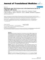
(BMW) diversion performance. Figure 1
illustrates configurations for MBT and
highlights the components within each. ABT
is an acronym for an Advanced Biological
Treatment process, which are covered in a
separate Technology Brief in this series and
further information is available on the Waste
Technology Data Centre concerning different
configurations of plant.
4
5
Compost-like Output (CLO) is also sometimes referred to as ‘stabilised biowaste’ or a soil conditioner; it is not the same as a source-
segregated waste derived ‘compost’ or ‘soil improver’ that will contain much less contamination and has a wider range of end uses
2. How it works
2.2 Waste Preparation
Residual waste requires preparation before
biological treatment or sorting of materials
can be achieved. Initial waste preparation
may take the form of simple removal of
contrary objects, such as mattresses, carpets
or other bulky wastes, which could cause
problems with processing equipment down-
stream.
Further mechanical waste preparation
techniques may be used which aim to prepare
the materials for subsequent separation
stages. The objective of these techniques
may be to split open refuse bags, thereby
liberating the materials inside; or to shred
and homogenise the waste into smaller
particle sizes suitable for a variety of
separation processes, or subsequent biological
treatment depending on the MBT process
employed.
A summary of the different techniques used
for waste preparation is provided in Table 1.
5
Figure 1: An illustration of the potential Mechanical Biological Treatment options
Biogas
Landfill
Landfill
Sorting before ABT
ABT before sorting e.g. biodrying
Pre-treatment before landfill
Waste
Preparation
Sorting
ABT
Compost like
outputs
Refuse
derived fuel
Recyclable
materials
Market failure/rejects
2. How it works
2.3 Waste Separation
A common aspect of many MBT plant used
for MSW management in the sorting of
mixed waste into different fractions using
mechanical means. As shown in Figure 1, the
sorting of material may be achieved before or
after biological treatment. No sorting is
required if the objective of the MBT process is
to pre-treat all the residual MSW to produce
a stabilised output for disposal to landfill.
Sorting the waste allows an MBT process to
separate different materials which are
suitable for different end uses. Potential end
uses include material recycling, biological
treatment, energy recovery through the
production of RDF, and landfill. A variety of
different techniques can be employed, and
most MBT facilities use a series of several
different techniques in combination to
achieve specific end use requirements for
different materials.
Separation technologies exploit varying
properties of the different materials in the
waste. These properties include the size and
shape of different objects, their density,
weight, magnetism, and electrical
conductivity. A summary of the different
options for waste separation is shown in
Table 2.
6
Ref Technique Principle Key Concerns
A Hammer Mill Material significantly reduced in size by
swinging steel hammers
Wear on Hammers, pulverising and
‘loss’ of glass / aggregates, exclusion of
pressurised containers
B Shredder Rotating knives or hooks rotate at a slow speed
with high torque. The shearing action tears or
cuts most materials
Large, strong objects can physically
damage, exclusion of pressurised
containers
C Rotating
Drum
Material is lifted up the sides of a rotating drum
and then dropped back into the centre. Uses
gravity to tumble, mix, and homogenize the
wastes. Dense, abrasive items such as glass or
metal will help break down the softer materials,
resulting in considerable size reduction of paper
and other biodegradable materials
Gentle action – high moisture of
feedstock can be a problem
D Ball Mill Rotating drum using heavy balls to break up or
pulverise the waste
Wear on balls, pulverising and ‘loss’ of
glass / aggregates
E Wet Rotating
Drum with
Knives
Waste is wetted, forming heavy lumps which
break against the knives when tumbled in the
drum
Relatively low size reduction. Potential
for damage from large contraries
F Bag Splitter A more gentle shredder used to split plastic bags
whilst leaving the majority of the waste intact
Not size reduction, may be damaged by
large strong objects
Table 1: Waste Preparation Techniques
2. How it works
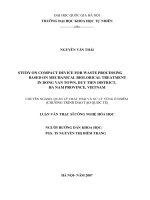
7
Figure 2: Waste separation using a trommel screen
Table 2: Waste Separation Techniques
Separation Technique Separation Property Materials targeted Key Concerns
1 Trommels and Screens Size Oversize – paper, plastic
Small – organics, glass, fines
Air containment and
cleaning
2 Manual Separation Visual examination Plastics, contaminants,
oversize
Ethics of role, Health &
Safety issues
3 Magnetic Separation Magnetic Properties Ferrous metals Proven technique
4 Eddy Current
Separation
Electrical Conductivity Non ferrous metals Proven technique
5 Wet Separation
Technology
Differential Densities Floats - Plastics, organics
Sinks - stones, glass
Produces wet waste
streams
6 Air Classification Weight Light – plastics, paper
Heavy – stones, glass
Air cleaning
7 Ballistic Separation Density and Elasticity Light – plastics, paper
Heavy – stones, glass
Rates of throughput
8 Optical Separation Diffraction Specific plastic polymers Rates of throughput
2. How it works
2.4 Biological Treatment
The biological element of an MBT process can
take place prior to or after mechanical sorting
of the waste, as illustrated in Figure 1. In
some processes all the residual MSW is
biologically treated to produce a stabilised
output for disposal to landfill and no sorting
is required. The biological processes used are
either:
• Aerobic Bio-drying
• Aerobic In-vessel composting
• Anaerobic digestion
Each approach has its own particular
application and examples of methodologies
are described in the case studies in the track
record section and in more detail on the
Waste Technology Data Centre.
There are a variety of different biological
treatment techniques which are used in MBT
plant. These are described in greater detail in
the Advanced Biological Treatment Brief, in
this series. Table 3 below outlines the key
categories of biological treatment.
Table 3: Biological Treatment options
2.5 Summary
This section illustrates that MBT systems can
be described as two simple concepts: either to
separate the waste and then treat; or to treat
the waste and then separate. In some
systems only biological treatment is required
to treat all the residual MSW before disposal
to landfill. Whilst a variety of treatment and
mechanical separation options are offered,
these need to be optimised in terms of the
outputs in order to find outlets for the
various materials / fuels derived from the
process (see Markets for the Outputs section).
8
Options Biological Treatment
I Aerobic - Bio-drying / Biostabilisation:
partial composting of the (usually) whole
waste
II Aerobic - In-Vessel Composting: may be
used to either biostabilise the waste or
process a segregated organic rich fraction
III Anaerobic Digestion: used to process an
segregated organic rich fraction
3. Markets and outlets for the outputs
In the UK, at present, the market or outlet for
many of the outputs from MBT is still under
development. Plants being specified today
will need to provide materials into as yet
undeveloped markets. It is prudent to install
or at least maintain the option of installing
for flexibility in the degree and types of
separation of materials that any proposed
plant can achieve.
The following section summarises some key
issues with regard to the outlets for outputs
from MBT systems for MSW.
3.1 Materials Recycling
Recyclables derived from the various MBT
processes are typically of a lower quality than
those derived from a separate household
recyclate collection system and therefore have
a lower potential for high value markets. The
types of materials recovered from MBT
processes almost always include metals
(ferrous and non-ferrous) and for many
systems this is the only recyclate extracted.
However these plant can help enhance overall
recycling levels and enable recovery of certain
constituent items that may not otherwise be
collected in household systems (e.g. batteries,
steel coat hangers, etc.).
Other materials which may be extracted from
MBT processes include glass, textiles, paper /
card, and plastics. The most common of these
is glass, which may be segregated with other
inert materials such as stones and ceramics.
These materials are typically segregated and
arise as the “dense” fraction from air
classifiers or ballistic separation (see Table 2
on mechanical waste preparation
technologies). This dense fraction could find
application for use as a low grade aggregate;
however this would be subject to achieving a
suitable quality material. This mixed material
from some processes has found application as
Alternative Daily Cover (ADC) at landfill sites,
though this would not count towards
recycling performance or diversion from
landfill.
Segregating glass for recycling from residual
waste or a mixed waste arising from an MBT
plant would require material-specific sorting
techniques if recycling into high-value
products is to be achieved. Examples of this
approach can be found both in MBT plant as
well as more traditional “dirty MRF”
processes treating mixed residual waste in
other countries. In these examples manual
sorting of glass has been applied to segregate
the material. However, labour costs in the UK
are considered to be high, and are likely to
preclude this approach as being uneconomic.
There are also significant issues with respect
to worker Health and Safety, and the
handling of broken glass objects from mixed
waste streams.
Textiles, paper and plastics, if extracted, are
unlikely to receive an income as a recyclate
and in some instances may not yield a positive
value. Most of these plant can experience
problems with the heavier textiles such as
carpets. Clearly none are likely to separate
textiles into different types of fibre.
9
3. Markets and outlets for the outputs
Although unlikely, paper can potentially be
separated for recycling but often it is
combined with textiles and plastics; recycling
markets or outlets for the material are very
limited. Manual sorting or more
sophisticated mechanical sorting can be
undertaken on this waste stream. The quality
of the paper will be lower than if source
segregated and the markets available will be
fewer and of lower value. With the
improving performance of kerbside recycling
schemes there has been an increase in the
quantity of paper separately collected for
recycling. This paper will be able to secure a
market, either in the UK or overseas, more
easily than paper separated in an MBT facility.
Consequently, few MBT processes attempt to
segregate paper for recycling, preferring
instead to utilise it as a high calorific value
Refuse Derived Fuel (RDF), which is easily
achieved using conventional mechanical
sorting techniques.
Any plastics separated from these processes
will almost always be mixed plastics. The use
of high-tech optical sorting technology, such
as Near Infra-Red (NIR), offers the potential to
recover high value material-specific waste
streams, such as segregated plastic by
polymer type. Application of such techniques
is currently rare in MBT processes, and its
effectiveness is yet to be fully proven in
residual waste applications. The capital costs
associated with installing such technologies
are high, and cost/benefits of adopting them
would be significantly influenced by the
effectiveness of any recycling achieved
upstream through kerbside collection systems
serving to limit the quantity of recyclable
materials present in residual waste.
For more information on the contribution of
MBT to Best Value Performance Indicators
and recycling see section 9, and for the latest
developments see the local authority
performance pages on the Defra website
/>ocalauth/perform-manage/index.htm and
/>PI%20FAQs.pdf
3.2 Use of compost-like outputs (CLO)
MBT processing of mechanically separated
organics can produce partially/fully stabilised
and sanitised CLO or partially stabilised
digestate material. Digestate material is
produced from an MBT process that uses
anaerobic digestion as the biological process.
CLO is usually the term used for an output
using an aerobic process such as bio-drying or
in-vessel composting. The potential
applications of these outputs are dependent
upon their quality and legislative and market
conditions. CLO and digestate has the
potential to be used as a source of organic
matter to improve certain low quality soils,
e.g. in the restoration of brown field sites, or
for landfill cap restoration.
A summary of the estimated size of the
potential market outlets for CLO is given in
table 4.
10
3. Markets and outlets for the outputs
It is generally assumed that CLO derived from
mixed waste will be of lower quality and
value compared to compost derived from
source-segregated materials, largely due to
higher contamination levels. Trials on mixed
waste derived materials have reported
8
large
amounts of physical contaminants (e.g. glass)
and levels of potentially toxic elements above
limits for the British Standards Institute (BSI)
Publicly Available Specification (PAS) 100: for
composted materials, in particular for zinc,
lead, cadmium and mercury. Table 5 shows
the limits for heavy metals and other criteria
for PAS 100 compost.
11
Material Application Potential market in Tonnes per year Source
Soil Conditioner / Organic
based output from MBT
Land Restoration /
Remediation
1,300,000 – 11,900,000
NB: a variety of scenarios considered
to constitute this range
Sita Trust
2005
6
Soil Conditioner / Organic
based output from MBT
Land Restoration /
Remediation
>6,000,000 WRAP
2002
7
Soil Conditioner / Organic
based output from MBT
Landfill Cap /
Restoration
1,200,000 – 4,600,000
NB: a variety of scenarios considered to
constitute this range
Sita Trust
2005
Soil Conditioner / Organic
based output from MBT
Landfill Cap /
Restoration
>5,000,000 WRAP
2002
Table 4: Market outlets for CLO
6
MBT: A Guide for Decision Makers- Processes, Policies and Markets, Juniper Consultancy 2003 (produced for SITA Trust
7
Research Analysis for the Market Potential for Lower Grade Composted Materials in the UK, WRc, 2002 (for WRAP)
8
Development of a dynamic housed windrow composting system: performance testing and review of potential use of end products, ORA
(March 2005) for Canford Environmental
Table 5: BSI PAS 100 criteria*
* BSI PAS 100 is only valid for composts derived from source segregated waste, by definition
Parameter BSI PAS 100 limit
Cadmium, ppm 1.5
Chromium, ppm 100
Copper, ppm 200
Mercury, ppm 1
Nickel, ppm 50
Lead, ppm 200
Zinc, ppm 400
Impurities >2mm 0.5%; of which 0.25% maximum can be plastic
Gravel & stones
>4mm <8% in grades other than coarse mulch;
>4mm in coarse mulch grade <16%
Pathogens E.coli 1000 cfu/g; No Salmonella in 25g
Microbial respiration rate
16 mg CO
2
/g organic matter/day
3. Markets and outlets for the outputs
The quality of CLO produced will vary with
different MBT technologies, the quality of
raw waste inputs, and the method and
intensity of waste preparation and separation
prior to biological treatment, as well as the
methods used to screen of the outputs.
Due to its low quality, opportunities to apply
CLO or digestate produced from mixed MSW
to land will be limited. As a waste, these
materials require a waste management
licence (WML) exemption in order to be used
on land. Currently, they can only be used on
non-agricultural land and must be shown to
be ecologically beneficial. A risk-based
assessment is needed in relation to their
contamination content, and the nature of the
land to which they are to be applied. This is
similar approach to regulations covering the
use of sewage sludge in agriculture. CLO or
digestate that is used on land must also meet
the requirements of the Animal By-Products
Regulations (ABPR).
If an outlet cannot be found for the CLO then
it may have to be disposed to landfill. This
will incur a disposal cost and any
biodegradability remaining will contribute to
local authority BMW landfill allowances
under LATS (the Landfill Allowance Trading
Scheme). For more information on LATS see
/>ocalauth/lats/index.htm.
Waste Management Licensing Regulations
Changes to the Waste Management Licensing
Regulations came into force on 1st July 2005
9
.
A waste management licence (WML)
exemption, under Paragraph 7A of the
regulations, is required by land
owners/managers before any compost or
digestate (fibre or effluent) derived from
source-segregated waste materials can be
applied to agricultural land
10
. CLO, derived
from mixed waste, is not allowed to be
applied to agricultural land. These outputs
may be applied to brownfield and restoration
land under a WML exemption, under
Paragraph 9A, provided that ecological
benefit is demonstrated.
The Government and the National Assembly
for Wales consulted in May 2006 on the
requirement for compost or digestate derived
from source-segregated materials for it to be
permitted to be spread to agricultural land,
under a Paragraph 7A WML Exemption. In
the light of consultation, the Government has
concluded that, for now, the source-
segregation requirement should remain.
However, the Government views this as an
interim measure, and will carry out work to
find a longer term, more sustainable solution
that will encourage the development of
[mixed MSW ABT] technologies that will
produce high standard outputs which could
be safely spread to land.
Animal By-Products Regulations (ABPR)
MBT plants that intend to use the stabilised
organic material on land (including landfill
cover) will be considered to be a composting
or biogas plant, and will fall within the scope
of the ABPR. These sites must therefore meet
all treatment and hygiene standards required
by source-segregated waste composting/
biogas plants.
Mixed MSW will contain household kitchen
(‘catering’) waste including meat, and as such
will, at least, fall under UK national ABPR
11
standards for catering waste containing meat.
12
9
The Waste Management Licensing (England and Wales) (Amendment and Related Provisions) (No. 3) Regulations 2005 (S.I. No. 1728)
10
Unless the Quality Protocol for Compost applies for source segregated biowaste - The Quality Protocol for the production and use of quality
compost from source-segregated biowaste, developed by the Business Resource Efficiency and Waste (BREW) programme, WRAP and the
Environment Agency, published March 2007
11
Animal By-products Regulations 2003 (SI 2003/1482); Wales (SI 2003/2756 W.267); Scotland (SSI 2003/411)
3. Markets and outlets for the outputs
In some cases it may also contain certain
commercial/industrial waste containing raw
meat or fish; classified as ‘Category 3’ animal
by-products. Category 3 animal by-products
must be treated in accordance with the EU
regulation
12
standards.
3.3 Production of biogas
An MBT plant that uses anaerobic digestion
(AD) as its biological process will produce
biogas. During AD, the biodegradable
material is converted into methane (CH
4
) and
carbon dioxide (together known as biogas),
and water, through microbial fermentation in
the absence of oxygen leaving a partially
stabilised wet organic mixture known as a
digestate.
The biogas can be used in a number of ways.
It can be used as a natural gas substitute
(distributed into the natural gas supply) or
converted into fuel for use in vehicles. More
commonly it is used to fuel boilers to produce
heat (hot water and steam), or to fuel
generators in combined heat and power
(CHP) applications to generate electricity, as
well as heat.
Biogas electricity production per tonne of
waste can range from 75 to 225 kWh, varying
according to the feedstock composition,
biogas production rates and electrical
generation equipment. Biogas is a source of
renewable energy, with electricity generated
from it being supporter by the Renewables
Obligation.
In most simple energy production
applications, only a little biogas pre-
treatment is required. Biogas used in a boiler
requires minimal treatment and compression,
as boilers are much less sensitive to hydrogen
sulfide and moisture levels, and can operate
at a much lower input gas pressure.
Where biogas is used for onsite electricity
generation, a generator similar to that used
in landfill gas applications can be used, as
these generators are designed to combust
moist gas containing some hydrogen sulfide.
Gas compression equipment may be required
to boost the gas pressure to the level
required by the generator.
Some electricity is used by the AD plant, but
any excess electricity produced can be sold
and exported via the local electricity
distribution network. Excess heat can also be
used locally in a district heating scheme, if
there is an available user.
For high specification applications (e.g.
vehicle fuel, natural gas substitute), or when
using more sophisticated electricity
generation equipment (e.g. turbines), biogas
will require more pre-treatment to upgrade
its quality. This includes the removal of
hydrogen sulphide (a corrosive gas); moisture
removal; pressurization to boost gas pressure;
and removing carbon dioxide to increase the
calorific value of the biogas. However, the
cost of the equipment required to upgrade
biogas can be prohibitive.
3.4 Materials Recovered for Energy
Where the MSW is sorted / treated to produce
a high calorific value waste stream comprising
significant proportions of the available
combustible materials such as mixed paper,
plastics and card, this stream may be known
as Refuse Derived Fuel (RDF - see Box 1)
13
12
Regulation EC 1774/2002 laying down health rules concerning animal by-products not intended for human consumption
3. Markets and outlets for the outputs
Potential outlets for RDF
Defra has identified 6 potential outlets for
RDF. The viability of some of these is
dependent on legislative changes being
made, which may or may not happen. The 6
potential outlets are:
1. Industrial intensive users for power, heat or
both (Combined Heat and Power - CHP)
2. Cement kilns
3. Purpose built incinerators with power
output or power and heat (CHP)
4. Co-firing with coal at power stations
5. Co-firing with fuels like poultry litter and
biomass which are eligible for Renewable
Obligation Certificates (ROCs – see section
3.3.2) in conventional technologies
6. Advanced thermal technologies, such as
pyrolysis and gasification which are ROC
eligible technology
RDF from a UK MBT facility is already utilised
at a cement works as an energy source,
replacing other fuels. Industrial intensive
energy users are not yet using RDF but some
interest from industry is being shown in the
market place.
14
The current prevalent term used for a fuel
produced from combustible waste is Refuse
Derived Fuel (RDF). The types of technologies
used to prepare or segregate a fuel fraction
from MSW include the MBT processes described
within this Brief.
A CEN Technical Committee (TC 343) is currently
progressing standardisation work on fuels
prepared from wastes, classifying a Solid
Recovered Fuel (SRF). Preliminary standards have
been published in June 2006, and are following
an evaluation process, during which the
functioning of the specifications will be verified.
The technical specifications classify the SRF by
thermal value, chlorine content and mercury
content. For example, the thermal value class
will be based on the number of megajoules one
kilogram of recovered fuel contains. In addition,
there are many characteristics for which no
specific values have been determined. Instead,
they can be agreed upon between the producer
and the purchaser of SRF.
Along with the standardisation process, a
validation project called QUOVADIS
( on solid recovered fuels
is currently being implemented.
It is anticipated that once standards are
developed and become accepted by users, then
SRF will become the terminology used by the
waste management industry. Other terminology
has also been introduced to the industry as
various fuel compositions may be prepared from
waste by different processes. Examples include
‘Biodegradable Fuel Product’ (BFP) and ‘Refined
Renewable Biomass Fuel’ (RRBF).
European standards for SRF are important for
the facilitation of trans-boundary shipments and
access to permits for the use of recovered fuels.
There may also be cost savings for co-
incineration plants as a result of reduced
measurements (e.g. for heavy metals) of
incoming fuels. Standards will aid the
rationalisation of design criteria for combustion
units, and consequently cost savings for
equipment manufacturers. Importantly standards
will guarantee the quality of fuel for energy
producers.
Within this Brief, Refuse Derived Fuel will be
used as a term to cover the various fuel products
processed from MSW.
Box 1: Fuel from mixed waste processing operations
3. Markets and outlets for the outputs
There is currently only one dedicated
conventional combustion plant (incinerator)
in the UK that uses RDF as a fuel to generate
electricity. Another facility which accepts
prepared fuel, (generated from raw MSW
delivered at the front end of the plant) which
could be termed crude RDF is also combusted
in a recently commissioned Fluidised-Bed
incinerator in Kent, illustrated in Table 6.
Table 6: Combustion technology plant
generating electricity from RDF in England
RDF may also be utilised within some
appropriate Advanced Thermal Treatment
(ATT) processes. A suitably scaled, dedicated
ATT plant could represent a part of an
integrated strategy in combination with MBT.
A separate Waste Management Technology
Brief, in this series, is available on the subject
of ATT processes.
The energy use incurred in the separation of
waste typically involves around 15 – 20% of
the energy value of the waste. If the RDF is to
be used as an energy source then a high
efficiency process (e.g. Advanced Thermal
Treatment or Incineration with Combined
Heat and Power) needs to be used, or the
RDF needs to be used as a fossil-fuel
replacement fuel to establish any
environmental benefit over directly
combusting the residual waste in an
incinerator. Not all ATT processes will offer
the efficiencies appropriate.
The advantage of co-combusting RDF at
power stations or other large thermal
processes is that the infrastructure may
already be in place; a disadvantage is that the
outlet for the fuel is subject to obtaining a
contract of sufficient duration and tonnage,
with a commercial partner. An estimate of
the potential market for RDF in the UK is
provided in the table 7 below.
Table 7: Estimated size of the RDF market
The co-combustion of RDF is an emerging
market. It is currently anticipated that cement
kilns along with large industrial energy users
and the power generation sector will provide
the majority of potential capacity for using
RDF. There is however, competition from
other wastes to be processed within the
cement production process including tyres,
some hazardous wastes, secondary liquid
fuels etc. Consequently it is expected that
there may be competition (and competitive
gate fees) for acceptance of RDF at cement
15
RDF Combustion
plant
Operator K tonnes/ year
Slough,
Berkshire
Slough Heat &
Power
100
Allington,
Kent
Kent
Enviropower
500
13
RDF Opportunities: Coal and Cement Industries, Fichtner Consulting, RRF 2004
14
Submission of Evidence to House of Commons Select Committee, January 2003
Output Outlet
Predicted
Market size
(t/a)
Source
RDF UK Cement
Kilns
350,000 Resource
Recovery
Forum,
2004
13
Packaging &
Packaging
waste (incl.
municipal
derived RDF)
UK Cement
Kilns
500,000 British
Cement
Association,
2003
14
RDF Paper
Industry
300,000 –
600,000
NB: Required
construction
of dedicated
RDF plant at
paper
mills
Resource
Recovery
Forum,
2004
3. Markets and outlets for the outputs
kilns. A local authority currently would have
to pay for the RDF to be used in a cement
kiln. Emphasis should be put on developing
sustainable markets for materials
As an emerging market there are also
potential risks in terms of the operations of
large thermal facilities accepting RDF from
mixed waste processing as a fuel source.
However, waste contractors are developing
relationships with the cement industry and
others to try and meet their specifications
and provide a useful industrial fuel and waste
recovery operation.
Renewable Energy
RDF is classified as a waste and therefore any
facility using the fuel will be subject to the
requirements of the Waste Incineration
Directive (WID). As with the cement industry,
power stations would need to be WID
compliant. This would represent a significant
capital investment for the industry. However
WID only requires an operator to upgrade
those facilities at a power station in which
waste is handled to WID standards
15
. If an
operator has more than one boiler then only
one would need to be upgraded. This might
make RDF a more attractive option for the
power generation industry.
Electricity generated from the biodegradable
fraction of waste in certain technologies is
eligible for support under the Renewables
Obligation (RO). Electricity recovered from
the biomass component of RDF qualifies for
support if it is generated in ‘advanced
conversion technologies’, including pyrolysis
or gasification plant (see the Advanced
Thermal Treatment Brief), or in a
conventional combustion facility with Good
Quality Combined Heat and Power (CHP)
Up-to-date information regarding RDF and
ROCs can be obtained from the DTI website
/>Also see the Defra New Technologies
Demonstrator Programme for demos using
RDF.
16
15
Written answers to Alan Whitehead MP from Ben Bradshaw, Minister of State for Defra, 07/03/2007
4. Track record
The concept of MBT originated in Germany
where it is an established waste treatment
method. Regulatory restrictions on landfill
space, the search for alternatives to
incineration and increased costs of landfill
disposal have been the major drivers for the
development of these technologies. The
largest European markets for established MBT
plant include Germany, Austria, Italy,
Switzerland and the Netherlands, with others
such as the UK growing fast. Furthermore,
other countries outside Europe are also using
this technology.
Since the early 1990s, MBT processes have
changed significantly, so today, numerous
configurations of plant have developed, and
these are provided by a variety of companies.
There are over 70 MBT facilities in operation
in Europe, with over 40 MBT facilities
operating in Germany. However, not all of
these facilities are commercial and some of
those included in Table 8 include pilot and
demonstration plants.
Table 8: Examples of MBT plant operational
in Europe
17
Technology Provider Country
Number
of Plants
Hese Umwelt (Leicester) UK 1
EcoDeco (ELWA) UK 1
Civic Environmental Systems
(Durham)
UK 1
New Earth Solutions (Dorset) UK 1
CRS (Argyll and Bute,
Northumberland)
UK 2
Hot Rot (Western Isles) UK 1
Sutco Germany 5
Electrowatt-Ekono Germany 1
Herhof Germany 3
Dranco Germany 2
ISKA Germany 1
Horstmann Germany 4
Wehrle Werk Germany 1
BTA Germany 1
BTA Italy 1
Dranco Italy 1
Ionics Itabila Italy 1
Snamprogetti Italy 1
Valorga Italy 1
EcoDeco Italy 4
Herhof Italy 1
Valorga Spain 2
Linde Spain 1
Dranco Spain 1
BTA/Roediger Poland 1
Citec Finland 1
Citec/Vagron Holland 1
Valorga Belgium 1
Valorga France 2
Valorga Netherlands 1
Dranco Switzerland 1
Dranco Austria 1
VKW Austria 1
VKW Italy 1
VKW Turkey 1
4. Track record
4.1 Case Studies
The following case studies illustrate examples
of MBT system using the different mechanical
preparation, separation and biological
treatment techniques, described in Section 2.
Shanks East London Sistema Ecodeco MBT
facility on Frog Island
This facility is designed to take up to 180,000
tonnes per year of mixed residual waste from
the East London Waste Authority. It is a fully
enclosed bio-drying system. Waste is shredded
before being placed into a bio-drying area
where the material is treated using a suction
forced-aeration system in the floor. The
material is biologically treated for two weeks.
The dry material is then put through a
mechanical separation process to remove
metals and a glass / aggregate fraction. The
remaining dried waste (consisting mainly of
dried organics, card, paper, plastics and other
miscellaneous materials) is highly calorific and
used as RDF. The RDF is currently used by a
cement kiln, however, it will be utilised by an
Advanced Thermal Treatment (ATT) process
operated by Novera Energy Ltd at the Ford
Dagenham plant, which will be part funded
by the Defra New Technologies Demonstrator
programme.
Bournemouth Council’s New Earth MBT
facility
The £4.4 million New Earth MBT facility based
at Poole in Dorset is designed to take 50,000
tonnes per year of mixed MSW. The waste is
shredded and an organic-rich fraction is
screened out. The organic fraction is then
composted in elongated piles (windrows)
placed on forced-aeration ducts inside one of
two composting buildings. The material is
turned using specialised machinery 3 times
during a two-week process. The material is
then composted in a second building with
suction forced aeration for a further two
weeks. The facility produces around 9,000
tonnes of compost-like output per year.
Earth Tech Western Isles MBT facility
This is a £10 million project to build 2
treatment facilities. The main facility in
Stornoway on the Isle of Lewis treats 21,000
tonnes per year of source-separated organics
and residual waste. Anaerobic digestion
(using Linde technology) is used to treat the
source separated waste and in-vessel
composting (by HotRot) is used to treat the
residual waste. Mixed residual MSW is
shredded and screened to produce a fine
organic fraction which is composted to
produce a CLO for landfill restoration.
Biffa/Leicester MBT facility and AD plant
This MBT facility (estimated to cost £20
million) has a capacity of up to 150,000
tonnes per year of mixed residual waste. The
facility is spread over two sites: Bursom, home
to a large ball mill used to crush the waste
before it is screened and classified into
various usable fractions; and Wanlip, where
an AD facility is used to process the fine
(<5mm) organic-rich fraction from the milled
waste. The AD process is designed to handle
up to around 50,000 tonnes per year. The AD
plant uses a two-stage process: first, the fines
are made into wet slurry that is then pumped
with air during a 24 hour aerobic hydrolysis
process; and second, this pre-treated
(biologically heated and acidified) slurry is
then sent to an 18 day thermophilic wet AD
process. The plant is expected to produce
enough biogas to provide 1.5 MW of
electricity. The digestate undergoes further
treatment to produce a CLO.
18
4. Track record
4.2 Summary
The case studies represent a selection of MBT
projects currently operational in the UK.
Numerous MBT projects can be found abroad
and especially across Europe, where MBT has
been well established for many years. MBT
process configurations can vary significantly
and can be designed to suit local market
conditions and the regulatory framework
specific to the country in which it operates.
More information on different MBT systems
can be found on the Environment Agency’s
website in the Waste Technology Data Centre
– www.environment-agency.gov.uk/wtd
MBT as illustrated by the case studies,
represent significant facilities, which are
capital intensive (see Cost section) and are
anticipated to be in operation for 15 – 25
years. With the emergent nature of
markets/outlets for outputs from such
processes, it is prudent to ensure sufficient
installed capacity for flexibility within any
plant (which may require new equipment,
etc) to adapt to the needs of the market over
time.
19
5. Contractual and financing issues
5.1 Grants & Funding
Development of MBT plant will involve
capital expenditure of several million pounds.
There are a number of potential funding
sources for Local Authorities planning to
develop such facilities, including:
Capital Grants: general grants may be
available from national economic initiatives
and EU structural funds;
Prudential Borrowing: the Local
Government Act 2003 provides for a
'prudential' system of capital finance controls;
PFI Credits and Private Sector Financing:
under the Private Finance Initiative a waste
authority can obtain grant funding from
central Government to support the capital
expenditure required to deliver new facilities.
This grant has the effect of reducing the
financing costs for the Private Sector, thereby
reducing the charge for the treatment service;
Other Private-Sector Financing: A
contractor may be willing to enter a contract
to provide a new facility and operate it. The
contractor’s charges for this may be expressed
as gate fees; and
Existing sources of local authority
funding: for example National Non-Domestic
Rate payments (distributed by central
government), credit (borrowing) approvals,
local tax raising powers (council tax), income
from rents, fees, charges and asset sales
(capital receipts). In practice capacity for this
will be limited.
The Government is encouraging the use of
different funding streams, otherwise known
as a ‘mixed economy’ for the financing and
procurement of new waste infrastructure to
reflect the varying needs of local authorities.
5.2 Contractual Arrangements
Medium and large scale municipal waste
management contracts are likely to be
through the Competitive Dialogue procedure
under the Public Contract Regulations (2006).
The available contractual arrangement
between the private sector provider (PSP) and
the waste disposal authority (or partnership)
may be one of the following:
Separate Design; Build; Operate; and
Finance: The waste authority contracts
separately for the works and services needed,
and provides funding by raising capital for
each of the main contracts. The contract to
build the facility would be based on the
council’s design and specification and the
council would own the facility once
constructed;
Design & Build; Operate; Finance: A
contract is let for the private sector to provide
both the design and construction of a facility
to specified performance requirements. The
waste authority owns the facility that is
constructed and makes separate
arrangements to raise capital. Operation
would be arranged through a separate
Operation and Maintenance contract;
Design, Build and Operate; Finance: The
Design and Build and Operation and
Maintenance contracts are combined. The
waste authority owns the facility once
constructed and makes separate
arrangements to raise capital;
Design, Build, Finance and Operate
(DBFO): This contract is a Design and Build
and Operate but the contractor also provides
the financing of the project. The contractor
designs, constructs and operates the plant to
agreed performance requirements. Regular
performance payments are made over a fixed
20
5. Contractual and financing issues
term to recover capital and financing costs,
operating and maintenance expenses, plus a
reasonable return. At the end of the contract,
the facility is usually transferred back to the
client in a specified condition;
DBFO with PFI: This is a Design, Build,
Finance and Operate contract, but it is
procured under the Private Finance Initiative.
In this case the waste authority obtains
funding for future payment obligations from
Government as a supplement to finance from
its own and private sector sources.
The majority of large scale waste
management contracts currently being
procured in England are Design, Build,
Finance and Operate (DBFO) contracts and
many waste disposal authorities in two tier
English arrangements (County Councils) are
currently seeking to partner with their Waste
Collection Authorities (usually District or
Borough Councils). Sometimes partnerships
are also formed with neighbouring Unitary
Authorities to maximise the efficiency of the
waste management service and make the
contract more attractive to the Private Sector
Provider.
Before initiating any procurement or funding
process for a new waste management
treatment facility, the following issues should
be considered: performance requirements;
waste inputs; project duration; project cost;
available budgets; availability of sites;
planning status; interface with existing
contracts; timescales; governance and decision
making arrangements; market appetite and
risk allocation.
Further guidance on these issues can be
obtained from the following sources:
• Local Authority funding
/>e/localauth/funding/pfi/index.htm
• The Local Government PFI project support
guide
www.local.odpm.gov.uk/pfi/grantcond.pdf
• For Works Contracts: the Institution of Civil
Engineers ‘New Engineering Contract’
(available at www.ice.org.uk).
• For large scale Waste Services Contracts
through PFI and guidance on waste sector
projects see the 4ps, local government's
project delivery organisation
/>=90&tp=Y
A number of PFI funded/contracted waste
management projects have and will continue
to involve large scale MBT technologies some
of these are shown in Table 9).
Table 9: Examples of PFI Contracts in Local
Authority Waste Management including MBT
technology
21
Year
Local
Authority
Lead
Contractor
Solutions
2003 East London Shanks 2 MBT with
Bio-drying
2003 Leicester Biffa MRF + AD
In
progress
Lancashire Global
Renewables
4 MBT + 5
Transfer
Stations
In
progress
Cambridgeshire Donarbon 2 MBT, EfW,
AD
In
progress
Northumberland SITA 3 Civic
Amenity
sites, MRF,
MBT,
composting
6. Planning and permitting issues
This section contains information on the
planning and regulatory issues associated
with MBT facilities based on legislative
requirements, formal guidance, good practice
and in particular drawing on information
contained in the Office of the Deputy Prime
Minister’s research report on waste planning
published in August 2004
16
.
6.1 Planning Application Requirements
All development activities are covered by
Planning laws and regulations. Minor
development may be allowed under
Permitted Development rights but in almost
all cases new development proposals for
waste facilities will require planning
permission.
Under certain circumstances new waste
facilities can be developed on sites previously
used for General Industrial (B2) or Storage
and Distribution (B8) activities. In practice
even where existing buildings are to be used
to accommodate new waste processes,
variations to existing permissions are likely to
be required to reflect changes in traffic
movements, emissions etc.
Under changes to the planning system
introduced in 2006 all waste development is
now classed as ‘Major Development’. This has
implications with respect to the level of
information that the planning authority will
expect to accompany the application and also
with respect to the likely planning
determination period. The target
determination periods for different
applications are:
• Standard Application – 8 weeks
• Major Development - 13 weeks
• EIA Development - 16 weeks
The principal national planning policy
objectives associated with waste management
activities are set out in Planning Policy
Statement (PPS) 10 ‘Planning for Sustainable
Waste Management’ published in July 2005.
Supplementary guidance is also contained
within the Companion Guide to PPS 10. .
Both of these documents can be accessed via
the Department of Communities and Local
Government (DCLG) website
17
.
PPS 10 places the emphasis on the plan led
system which should facilitate the
development of new waste facilities through
the identification of sites and policies in the
relevant local development plan. Separate
guidance on the content and validation of
planning applications is also available from
DCLG through their website
18
. Individual
Planning Authorities can set out their own
requirements with respect to supporting
information and design criteria through
Supplementary Planning Documents linked to
the Local Development Framework. It is
important that prospective developers liaise
closely with their Local Planning Authorities
over the content and scope of planning
applications.
6.2 Key Issues
When considering the planning implications
of an MBT facility the key issues that will
need to be considered are common to most
waste management facilities and are:
• Plant/Facility Siting;
• Traffic;
• Air Emissions / Health Effects;
• Dust / Odour;
• Flies, Vermin and Birds;
• Noise;
22
16
/>17
/>18
/>6. Planning and permitting issues
• Litter;
• Water Resources;
• Visual Intrusion; and
• Public Concern.
A brief overview of the planning context for
each of these issues is provided below.
6.3 Plant Siting
PPS 10 and its Companion Guide contains
general guidance on the selection of sites
suitable for waste facilities. This guidance
does not differentiate between facility types
but states that:
“Most waste management activities are now
suitable for industrial locations, many fall
within the general industrial class in the Use
Classes Order.
19
The move towards facilities and processes
being enclosed within purpose designed
buildings, rather than in the open air, has
accentuated this trend. The guidance goes on
to state:
“With advancement in mitigation techniques,
some waste facilities may also be considered
as light industrial in nature and therefore
compatible with residential development. In
more rural areas, redundant agricultural and
forestry buildings may also provide suitable
opportunities, particularly for the
management of agricultural wastes”
Mixed waste processing (such as MBT) can
take place in many different buildings at a
variety of locations but the following issues
should be considered:
• MBT processes can be similar in appearance
and characteristics to various process
industries. It would often be suitable to
locate facilities on land previously used for
general industrial activities or land
allocated in development plans for such
(B2) uses;
• Facilities are likely to require good
transport infrastructure. Such sites should
either be located close to the primary road
network or alternatively have the potential
to be accessed by rail or barge;
• The location of such plants together with
other waste operations such as MRFs and
thermal treatment plants can be
advantageous. The potential for co-
location of such facilities on resource
recovery parks or similar is also highlighted
in the Companion Guide; and
• General concerns about bio-aerosols from
biological processing may require an MBT
site to be located away from sensitive
receptors.
6.4 Traffic
Centralised waste facilities will most likely be
served by large numbers of HGVs with a
potential impact on local roads and the
amenity of local residents. It is likely that the
site layout/road configuration will need to be
suitable to accept a range of light and heavy
23
19
The Town and Country Planning (Use Classes) Order 1987. SI 1987 No. 764