CMOS VLSI Design - Lecture 1: Introduction ppt
Bạn đang xem bản rút gọn của tài liệu. Xem và tải ngay bản đầy đủ của tài liệu tại đây (397.8 KB, 43 trang )
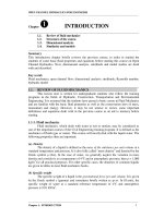
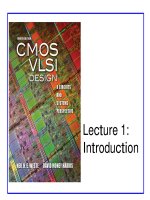
Lecture 1:
Introduction
CMOS VLSI Design
4th Ed.
0: Introduction 2
Introduction
Integrated circuits: many transistors on one chip.
Very Large Scale Integration (VLSI): bucketloads!
Complementary Metal Oxide Semiconductor
– Fast, cheap, low power transistors
Today: How to build your own simple CMOS chip
– CMOS transistors
– Building logic gates from transistors
– Transistor layout and fabrication
Rest of the course: How to build a good CMOS chip
CMOS VLSI Design
4th Ed.
0: Introduction 3
Silicon Lattice
Transistors are built on a silicon substrate
Silicon is a Group IV material
Forms crystal lattice with bonds to four neighbors
Si SiSi
Si SiSi
Si SiSi
CMOS VLSI Design
4th Ed.
0: Introduction 4
Dopants
Silicon is a semiconductor
Pure silicon has no free carriers and conducts
poorly
Adding dopants increases the conductivity
Group V: extra electron (n-type)
Group III: missing electron, called hole (p-type)
As SiSi
Si SiSi
Si SiSi
B SiSi
Si SiSi
Si SiSi
-
+
+
-
CMOS VLSI Design
4th Ed.
0: Introduction 5
p-n Junctions
A junction between p-type and n-type semiconductor
forms a diode.
Current flows only in one direction
p-type n-type
anode
cathode
CMOS VLSI Design
4th Ed.
0: Introduction 6
nMOS Transistor
Four terminals: gate, source, drain, body
Gate – oxide – body stack looks like a capacitor
– Gate and body are conductors
– SiO
2
(oxide) is a very good insulator
– Called metal – oxide – semiconductor (MOS)
capacitor
– Even though gate is
no longer made of metal
n+
p
GateSource Drain
bulk Si
SiO
2
Polysilicon
n+
Body
CMOS VLSI Design
4th Ed.
0: Introduction 7
nMOS Operation
Body is usually tied to ground (0 V)
When the gate is at a low voltage:
– P-type body is at low voltage
– Source-body and drain-body diodes are OFF
– No current flows, transistor is OFF
n+
p
GateSource Drain
bulk Si
SiO
2
Polysilicon
n+
D
0
S
CMOS VLSI Design
4th Ed.
0: Introduction 8
nMOS Operation Cont.
When the gate is at a high voltage:
– Positive charge on gate of MOS capacitor
– Negative charge attracted to body
– Inverts a channel under gate to n-type
– Now current can flow through n-type silicon from
source through channel to drain, transistor is ON
n+
p
GateSource Drain
bulk Si
SiO
2
Polysilicon
n+
D
1
S
CMOS VLSI Design
4th Ed.
0: Introduction 9
pMOS Transistor
Similar, but doping and voltages reversed
– Body tied to high voltage (V
DD
)
– Gate low: transistor ON
– Gate high: transistor OFF
– Bubble indicates inverted behavior
SiO
2
n
GateSource Drain
bulk Si
Polysilicon
p+ p+
CMOS VLSI Design
4th Ed.
0: Introduction 10
Power Supply Voltage
GND = 0 V
In 1980’s, V
DD
= 5V
V
DD
has decreased in modern processes
– High V
DD
would damage modern tiny transistors
– Lower V
DD
saves power
– Lower V -> increase f
V
DD
= 3.3, 2.5, 1.8, 1.5, 1.2, 1.0, …
CMOS VLSI Design
4th Ed.
0: Introduction 11
Transistors as Switches
We can view MOS transistors as electrically
controlled switches
Voltage at gate controls path from source to drain
g
s
d
g = 0
s
d
g = 1
s
d
g
s
d
s
d
s
d
nMOS
pMOS
OFF
ON
ON
OFF
CMOS VLSI Design
4th Ed.
0: Introduction 12
0
V
DD
A Y
GND
CMOS Inverter
A Y
0 1
1 0
A Y
OFF
ON
1
ON
OFF
CMOS VLSI Design
4th Ed.
0: Introduction 13
CMOS NAND Gate
A B Y
0 0 1
0 1 1
1 0 1
1 1 0
OFFOFF
ON
ON
1
1
OFFON
OFF
ON
0
1
ON OFF
ON
OFF
1
0
ON ON
OFF
OFF
0
0
A
B
Y
CMOS VLSI Design
4th Ed.
0: Introduction 14
CMOS NOR Gate
A B Y
0 0 1
0 1 0
1 0 0
1 1 0
A
B
Y
CMOS VLSI Design
4th Ed.
0: Introduction 15
3-input NAND Gate
Y pulls low if ALL inputs are 1
Y pulls high if ANY input is 0
A
B
Y
C
CMOS VLSI Design
4th Ed.
0: Introduction 16
CMOS Fabrication
CMOS transistors are fabricated on silicon wafer
Lithography process similar to printing press
On each step, different materials are deposited or
etched
Easiest to understand by viewing both top and
cross-section of wafer in a simplified manufacturing
process
CMOS VLSI Design
4th Ed.
0: Introduction 17
Inverter Cross-section
Typically use p-type substrate for nMOS transistors
Requires n-well for body of pMOS transistors
n+
p substrate
p+
n well
A
Y
GND
V
DD
n+
p+
SiO
2
n+ diffusion
p+ diffusion
polysilicon
metal1
nMOS transistor pMOS transistor
CMOS VLSI Design
4th Ed.
0: Introduction 18
Well and Substrate Taps
Substrate must be tied to GND and n-well to V
DD
Metal to lightly-doped semiconductor forms poor
connection called Shottky Diode
Use heavily doped well and substrate contacts / taps
n+
p substrate
p+
n well
A
Y
GND
V
DD
n+p+
substrate tap
well
tap
n+ p+
CMOS VLSI Design
4th Ed.
0: Introduction 19
Inverter Mask Set
Transistors and wires are defined by masks
Cross-section taken along dashed line
GND V
DD
Y
A
substrate tap
well tap
nMOS transistor
pMOS transistor
CMOS VLSI Design
4th Ed.
0: Introduction 20
Detailed Mask Views
Six masks
– n-well
– Polysilicon
– n+ diffusion
– p+ diffusion
– Contact
– Metal
Metal
Polysilicon
Contact
n+ Diffusion
p+ Diffusion
n well
CMOS VLSI Design
4th Ed.
0: Introduction 21
Fabrication
Chips are built in huge factories called fabs
Contain clean rooms as large as football fields
Courtesy of International
Business Machines Corporation.
Unauthorized use not permitted.
CMOS VLSI Design
4th Ed.
0: Introduction 22
Fabrication Steps
Start with blank wafer
Build inverter from the bottom up
First step will be to form the n-well
– Cover wafer with protective layer of SiO
2
(oxide)
– Remove layer where n-well should be built
– Implant or diffuse n dopants into exposed wafer
– Strip off SiO
2
p substrate
CMOS VLSI Design
4th Ed.
0: Introduction 23
Oxidation
Grow SiO
2
on top of Si wafer
– 900 – 1200 C with H
2
O or O
2
in oxidation furnace
p substrate
SiO
2
CMOS VLSI Design
4th Ed.
0: Introduction 24
Photoresist
Spin on photoresist
– Photoresist is a light-sensitive organic polymer
– Softens where exposed to light
p substrate
SiO
2
Photoresist
CMOS VLSI Design
4th Ed.
0: Introduction 25
Lithography
Expose photoresist through n-well mask
Strip off exposed photoresist
p substrate
SiO
2
Photoresist