program c for the microprocessor engineer
Bạn đang xem bản rút gọn của tài liệu. Xem và tải ngay bản đầy đủ của tài liệu tại đây (7.71 MB, 433 trang )
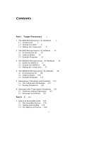
Contents
Part I Target Processors
1
1 The 6809 Microprocessor: Its Hardware 2
1.1 Architecture 3
1.2 Outside the 6809 6
1.3 Making the Connection 9
2 The 6809 Microprocessor: Its Software 19
2.1 Its Instruction Set 19
2.2 Address Modes 30
2.3 Example Programs 41
3 The 68000/8 Microprocessor : Its Hardware 56
3.1 Inside the 68000/8 57
3.2 Outside the 68000/8 64
3.3 Making the Connection 71
4 The 68000/8 Microprocessor: Its Software 86
4.1 Its Instruction Set 86
4.2 Address Modes 106
4.3 Example Programs 114
5 Subroutines, Procedures and Functions 122
5.1 The Call-Return Mechanism 123
5.2 Passing Parameters 129
6 Interrupts plus Traps equals Exceptions 141
6.1 Hardware Initiated Interrupts 143
6.2 Interrupts in Software 161
Part II C 167
7 Source to Executable Code 168
7.1 The Assembly Process 170
7.2 Linking and Loading 178
7.3 The High-Level Process 189
v
vi Contents
8 Naked C 199
8.1 A Tutorial Introduction 200
8.2 Variables and Constants 202
8.3 Operators, Expressions and Statements 213
8.4 Program Flow Control 224
9 More Naked C 236
9.1 Functions 236
9.2 Arrays and Pointers 245
9.3 Structures 258
9.4 Headers and Libraries 271
10 ROMable C 278
10.1 Mixing Assembly Code and Starting Up 278
10.2 Exception Handling 286
10.3 Initializing Variables 291
10.4 Portability 297
Part III Project in C 309
11 Preliminaries 310
11.1 Specification 313
11.2 System Design 315
12 The Analog World 323
12.1 Signals 323
12.2 Digital to Analog Conversion 329
12.3 Analog to Digital Conversion 337
13 The Target Microcomputer 345
13.1 6809 – Target Hardware 345
13.2 68008 – Target Hardware 350
14 Software in C 355
14.1 Data Structure and Program 355
14.2 6809 – Target Code 359
14.3 68008 – Target Code 370
15 Looking For Trouble 383
15.1 Simulation 384
15.2 Resident Diagnostics 397
15.3 In-Circuit Emulation 408
16 C'est la Fin 416
16.1 Results 416
16.2 More Ideas 420
Contents vii
A Acronyms and Abbreviations 423
List of Figures
1.1 Internal 6809/6309 structure. 4
1.2 6809 pinout. 7
1.3 A snapshot of the 6809 MPU reading data from a peripheral device. 10
1.4 Sending data to the outside world. 11
1.5 The structure of a synchronous common-bus microcomputer. 12
1.6 An elementary address decoding scheme. 14
1.7 A simple byte-sized output port. 15
1.8 Talking to a 6116 2 kbyte static RAM chip. 15
1.9 Interfacing a 6821 Peripheral Interface Adapter to the 6809. 17
2.1 Postbyte for pushing and pulling. 20
2.2 Moving 16-bit data at òne go'. 22
2.3 Stacking registers in memory. 23
2.4 16-bit binary to decimal string conversion. 48
2.5 Evaluating factorial n. 51
2.6 A memory map of the factorial process. 52
3.1 Internal structure pf the 68000. 58
3.2 Internal 68008 structure. 63
3.3 68000 and 68008 DIL packages. 65
3.4 Memory Organization for the 68000. 67
3.5 The structure of an asynchronous common-bus micro-computer. 72
3.6 The 68000/8 Read cycle. 73
3.7 The 68000/8 Write cycle. 75
3.8 A simple address decoder with no-wait feedback circuitry. 77
3.9 A DTACK generator for slow devices. 78
3.10 A simple word-sized output port. 80
3.11 Interfacing 6264 RAM ICs to the 68000 MPU. 81
3.12 Fast EPROM interface. 82
3.13 Interfacing the 68230 PI/T to the 68000's buses. 83
3.14 Interfacing a 6821 Peripheral Interface Adapter to the 68000. 84
4.1 Multiple moves to and from memory. 90
4.2 Multiple precision addition. 93
4.3 Using DBcc to implement a loop structure. 101
4.4 Two examples of machine coding. 114
5.1 Subroutine calling. 124
5.2 Saving the return address on the Stack. 126
5.3 The stack when executing the code of Table 5.3(b), viewed as word-oriented. 128
viii
LIST OF FIGURES ix
5.4 The Stack corresponding to Table 5.6. 132
5.5 The Stack used for the BLOCK_COPY subroutine. 134
5.6 The 6809 System stack organized by the array averaging subroutine. 136
5.7 The 68000 System stack organized by the array-averaging subroutine. 138
6.1 Detecting and measuring an asynchronous external event. 142
6.2 Interrupt logic for the 6809 and 68000 processors. 145
6.3 Using a priority encoder to compress 7 lines to 3-line code. 146
6.4 How the 6809 responds to an interrupt request 149
6.5 How the 68000 responds to an interrupt request 151
6.6 Using an external interrupt flag to drive a level-sensitive interrupt line. 153
6.7 Servicing four peripherals with one interrupt. 157
6.8 External interrupt hardware for the 68000 MPU. 158
7.1 Onion skin view of the steps leading to an executable program. 170
7.2 Assembly-level machine code translation. 172
7.3 Assembly environment. 188
7.4 Syntax tree for sum = (n+1) * n/2; 191
7.5 The Whitesmiths C compiler process. 194
8.1 Structure of C programs. 203
8.2 Properties of simple object types. 204
8.3 Basic set of C data types. 205
8.4 Type promotions. 222
8.5 Simple 2-way decisions. 224
8.6 Using else-if to make a multi-way decision. 227
8.7 switch-case multi-way decision. 229
8.8 Loop constructs. 231
9.1 Layout of C programs. 237
9.2 The System stack as seen from within power(), lines 21 – 38. 243
9.3 Array storage in memory. 249
9.4 A simple write-only port at 0x9000. 255
9.5 Register structure of a 6821 PIA. 262
11.1 A typical long-persistence display. 311
11.2 Characteristic scrolling display of a time-compressed memory. 312
11.3 Block diagram of the electrocardiograph time compressed memory. 316
11.4 A broad outline of system development. 318
11.5 Fundamental chip-level design. 320
11.6 A cost versus production comparison. 322
12.1 The quantization process. 325
12.2 The analog–digital process. 328
12.3 Illustrating aliasing. 329
12.4 A 4th-order anti-aliasing filter. 330
12.5 The R-2R current D/A converter. 331
12.6 Conversion relationships for the network of Fig. 12.5. 333
12.7 A real-world transfer characteristic. 334
x LIST OF FIGURES
12.8 The AD7528 dual D/A converter. 335
12.9 Interfacing the AD7528 to a microprocessor. 336
12.10 A 3-bit flash A/D converter. 338
12.11 A software controlled successive approximation D/A converter. 339
12.12 Functional diagram of the AD7576 A/D converter. 340
12.13 Interfacing the AD7576 to a microprocessor. 342
12.14 Aperture error. 343
13.1 The 6809-based embedded microprocessor implementation. 347
13.2 A PAL-based 6809 address decoder implementation. 349
13.3 The 68008-based embedded microprocessor implementation. 352
13.4 A PAL-based 68008 address decoder implementation. 353
14.1 Data stored as a circular array. 356
15.1 Tracing function sum_of_n(). 392
15.2 Illustrating the function path in reaching line 27. 393
15.3 Simulating the time-compressed memory software. 394
15.4 Simulating an interrupt entry into update(). 395
15.5 Mixed-mode simulation using XRAY68K. 396
15.6 Free-running your microprocessor. 398
15.7 One free-run cycle, showing RAM, A/D and DIG_O/P Enables. 399
15.8 The output_test() traces. 404
15.9 A typical PC-based ICE configuration. 410
16.1 Typical X and Y waveforms, showing two ECG traces covering 2 s. 420
List of Tables
2.1 Move instructions. 21
2.2 Arithmetic operations 24
2.3 Shifting Instructions. 26
2.4 Logic instructions. 27
2.5 Data test operations. 28
2.6 Operations which affect the Program Counter. 29
2.7 The M6809 instruction set 33
2.8 Initializing a 256-byte array. 34
2.9 Source code for sum of n integers program. 45
2.10 Object code generated from Table 2.9. 46
2.11 A superior implementation. 47
2.12 16-bit binary to an equivalent ASCII-coded decimal string. 49
2.13 Fundamental factorial-n code. 53
2.14 Factorial using a look-up table. 54
4.1 Move instructions. 88
4.2 Arithmetic operations. 91
4.3 Shifting instructions. 95
4.4 Logic Instructions. 97
4.5 Bit-level instructions. 98
4.6 Data testing instructions. 99
4.7 Instructions which affect the Program Counter. 100
4.8 Summary of 68000 instructions. 105
4.9 A summary of 68000 address modes. 113
4.10 Object code for sum of n integers program. 115
4.11 A superior implementation. 116
4.12 Binary to decimal string conversion. 118
4.13 Mathematical evaluation of factorial n. 119
4.14 Factorial using a look-up table. 120
5.1 Subroutine instructions. 125
5.2 A simple subroutine giving a fixed delay of 100 ms when called. 127
5.3 Transparent 100 ms delay subroutine. 129
5.4 Using a register to pass the delay parameter. 130
5.5 Using a static memory location to pass the delay parameter. 131
5.6 Using the stack to pass the delay parameter. 132
5.7 Making a copy of a block of data of arbitrary length. 133
5.8 Using a frame to acquire temporary data; 6809 code. 137
5.9 Using a Frame to acquire temporary data; 68000 code. 139
xi
xii LIST OF TABLES
6.1 6809 code displaying heart rate on an oscilloscope. 155
6.2 68000 code displaying heart rate on an oscilloscope. 160
6.3 Exception related instructions. 162
7.1 Source code for the absolute assembler. 173
7.2 A typical error file. 173
7.3 Listing file produced from the source code in Table 7.1. 174
7.4 Symbol file produced from the absolute source of Table 7.1. 174
7.5 Some common absolute object file formats. 176
7.6 A simple macro creating the modulus of the target operand. 177
7.7 Assembling the Display module with the Microtec Relocatable assembler. 181
7.8 Module 2 after assembly. 183
7.9 Module 3 after assembly. 184
7.10 Linking the three source modules. 185
7.11 Output from the Microtec linker. 187
7.12 A possible Lexical analysis of sum = (n+1)*n/2; 190
7.13 6809 target code for sum = (n+1) * n/2; 193
7.14 Passing a simple program through the compiler of Fig. 7.5. 197
8.1 Definition of function sum_of_n(). 200
8.2 Variable storage class 208
8.3 Initializing variables. 210
8.4 C operators, their precedence and associativity. 215
8.5 Bitwise AND and Shift operations. 218
8.6 A nested if Real-Time Clock interrupt service routine. 225
8.7 An else-if Real-Time Clock interrupt service routine. 226
8.8 Generating factorials using the else-if construct. 228
8.9 Generating factorials using the switch-case construct. 230
8.10 Generating factorials using a while loop. 232
8.11 Generating factorials using a for loop. 234
9.1 The C program as a collection of functions. 240
9.2 Generating factorials using a look-up table. 247
9.3 Altering an array with a function. 250
9.4 Sending out a digit to a 7-segment port. 256
9.5 Displaying and updating heartbeat. 260
9.6 The PIA as a structure of pointers. 265
9.7 Sending pointers to structures to a function. 267
9.8 Unions. 270
9.9 Using #define for text replacement. 272
9.10 A typical math.h library header (with added comments). 276
10.1 Elementary startup for a 6809-based system. 280
10.2 Using arrays of pointers to functions to construct a vector table. 281
10.3 A simple Startup/Vector routine for a 68000-based system. 282
10.4 A C-compatible assembler function evaluating the square root. 283
10.5 Using in-line assembly code to set up the System stack. 284
10.6 Calling a resident function at a known address. 286
10.7 6809 startup for the system of Table 9.5. 287
LIST OF TABLES xiii
10.8 68000 startup for the system of Table 9.5. 288
10.9 clock() configured as an interrupt function. 290
10.10A startup for the Aztec compiler initializing statics/globals. 294
10.11A typical lod68k file to produce an image of initialized data in ROM 295
10.12A startup initializing statics/globals and setting up the DPR for zero page. 296
10.13Zero-page storage with the Cosmic 6809 compiler. 297
10.14A portable C program using ANSII library I/O routines. 299
10.15Compiling the same source with a spectrum of CPUs. 303
10.16Tailoring the ANSII I/O functions to suit an embedded target. 305
12.1 Quantization parameters. 326
12.2 C driver for Fig. 12.11. 340
14.1 The fundamental C coding. 357
14.2 The hard_09.h header file. 359
14.3 6809 code resulting from Tables 14.1 and 14.2. 362
14.4 The 6809 Time Compressed Memory Startup. 363
14.5 The machine-code file for the 6809-based time-compressed memory. 364
14.6 The @port directive. 365
14.7 Using _asm() to terminate a NMI/IRQ type interrupt service function. 366
14.8 Optimized 6809 code. 370
14.9 68000 code resulting from Tables 14.1 and 14.2. 373
14.10The 68000 Time Compressed Memory Startup. 375
14.11Machine-code file from Tables 14.9 and 14.10. 376
14.12The @port directive. 377
14.13Using _asm() to terminate an interrupt service function. 378
14.14Optimized 68000 based code. 381
15.1 Simulating the program of Table 4.10. 386
15.2 Tracing the program of Table 2.9. 387
15.3 Tracing a C function. 389
15.4 A report on the variables used in the 68008 TCM system of Table 15.5. 390
15.5 Complete 68008 package, including resident diagnostics. 403
15.6 Code for the 68008 implementation. 407
15.7 An alternative RAM testing module for the 6809 system. 408
15.8 Memory Mapping and Testing. 412
15.9 A window into the hardware using an ICE. 413
16.1 A 6809-based assembly-level coding. 417
16.2 A 68008-based assembly-level coding. 419
PART I
Target Processors
A major advantage of the use of a high-level language is its independence of
the hardware its generated code will eventually run on; that is, its portability.
However, one of the main strands of this book is the interaction of software with
its hardware environment, and thus it is essential to use real products in both
domains. For clarity, rather than describing a multitude of devices, most of the
examples are based on just two microprocessors. Two, rather than one, not to
loose sight of the portability aspects of high-level code.
In this part I describe the Motorola 6809 and 68000/8 microprocessors, the
chosen devices. This gives us a hardware target spectrum ranging from 8 through
32-bit architecture. As both microprocessors share a common ancestor, the com-
plexity is reduced compared with a non-related selection. Where necessary, other
processors are used as examples, but in general the principles are similar irre-
spective of target. If the hardware detail seems excessive to a reader with a
software background, much may be ignored if building the miniproject circuitry
of Part 3 is to be omitted.
CHAPTER 1
The 6809 Microprocessor: Its
Hardware
The microprocessor revolution began in 1971 with the introduction of the Intel
4004 device. This featured a 4-bit data bus, direct addressing of 512 bytes of
memory and 128 peripheral ports. It was clocked at 108 kHz and was imple-
mented with a transistor count of 2300. Within a year, the 8-bit 200 kHz 8008
appeared, addressing 16 kbyte of memory and needing a 3500 transistor imple-
mentation. The improved 8080 replacement appeared in 1974, followed a few
months later by the Motorola 6800 MPU [1]. Both processors could directly ad-
dress 64 kbytes of memory through a 16-bit address bus and could be clocked at
up to 2 MHz. These two families, together with descendants and inspired close
relatives, have remained the industry standards ever since.
The Motorola 6800 MPU [2] was perceived to be the easier of the two to use
by virtue of its single 5 V supply requirement and a clean internal structure. The
8085 MPU is the current state of the art Intel 8-bit device. First produced in
1976, it has an on-board clock generator and requires only a single power supply,
but has a virtually identical instruction set to the 8080 device. Soon after Zilog
produced its Z80 MPU which was upwardly compatible with Intel's offering, then
the market leader, with a much extended instruction set and additional internal
registers [3].
The Motorola 6802/8 MPUs (1977) also have internal clock generators, with the
former featuring 128 bytes of on-board RAM. This integration of support mem-
ory and peripheral interface leads to the single-chip microcomputer unit (MCU) or
micro-controller, exemplified by the 6801, 6805 and 8051 MCU families [4]. The
6809 MPU introduced in 1979 [5, 6, 7] was seen as Motorola's answer to Zilog's Z80
and these both represent the most powerful 8-bit devices currently available. By
this date the focus was moving to 16- and 32-bit MPUs, and it is unlikely that
there will be further significant developments in general-purpose 8-bit devices.
Nevertheless, these latter generation 8-bit MPUs are powerful enough to act as the
controller for the majority of embedded control applications, and their architec-
ture is sophisticated enough to efficiently support the requirements of high-level
languages; more of which in later chapters. Furthermore, many MCU families
have a core and language derived from their allied 8-bit MPU cousins.
2
ARCHITECTURE 3
1.1 Architecture
The internal structure of a general purpose microprocessor can be partitioned
into three functional areas:
1. The mill.
2. Register array.
3. Control circuitry.
Figure 1.1 shows a simplified schematic of the 6809 MPU viewed from this per-
spective.
THE MILL
A rather old fashioned term used by Babbage [8] for his mechanical computer
of the last century to identify the arithmetic and logic processor which `ground'
the numbers. In our example the 6809 has an 8-bit arithmetic logic unit (ALU)
implementing Addition, Subtraction, Multiplication, AND, OR, Exclusive-OR, NOT
and Shift operations. Associated with the ALU is the Code Condition (or Sta-
tus) register (CCR). Five of the eight CCR bits indicate the status of the result of
ALU processes. They are: C indicating a Carry or borrow, V for 2's complement
oVerflow, Z for a Zero result, N for Negative (or bit 7 = 1) and H for the Half carry
between bits 3 and 4. These flags are set as a result of executing an instruction,
and are normally used either for testing and acting on the status of a process, or
for multiple-byte operations. The remaining three bits are associated with inter-
rupt handling. The I bit is used to lock out or mask the IRQ interrupt, and the
F bit carries out the same function for the FIRQ interrupt. During an interrupt
service routine the E flag may be consulted to see if the Entire register state has
been saved (IRQ, NMI and SWI) or not (FIRQ). More details are given in Section 6.1.
REGISTER ARRAY
The 6809 has two Data registers, termed Accumulators A and B. These Data reg-
isters are normally targeted by the ALU as the source and destination for at least
one of its operands. Thus ADDA #50 adds 50 to the contents of Accumulator_A (in
register transfer language, RTL, this is symbolized as [A] <- [A] + 50, which
reads `the contents of register A become the original contents of A plus 50'). Op-
erations requiring one operand can seemingly be done directly on external mem-
ory; for example, INC 6000h which increments the contents of location 6000h
([6000] <- [6000] + 1). The suffix h indicates the hexadecimal number base,
whilst b denotes binary. However, in reality the MPU executes this by bringing
down the contents of 6000h (written as [6000]), uses the ALU to add one and
returns it. Whilst this fetch and execute process is invisible to the programmer,
the penalty is space and time; INC M (3 bytes length) takes 7 µs and INCA or INCB
(1 byte length) takes 2 µs (at a 1 MHz clock rate). Thus while it is always better
to use the Data registers for operands, this is difficult in practice because there
are only two such registers. Unlike the older 6800 MPU, the 6809's two 8-bit Data
4 C FOR THE MICROPROCESSOR ENGINEER
Figure 1.1 Internal 6809/6309 structure.
ARCHITECTURE 5
registers can be concatenated to one 16-bit double register A:B; the D Accumu-
lator. A few operations such as Add (e.g. ADDD #4567) can directly handle this.
But although the 6809 has pretensions to be a 16-bit MPU, the ALU is only 8-bits
wide and instructions such as this require two passes; but they are nevertheless
faster than two single operations.
Six dedicated Address registers are accessible to the programmer and are as-
sociated with generating addresses of program and operand bytes external to the
processor. The Program Counter (PC) always points to the current program byte
in memory, and is automatically incremented by the number of operation bytes
during the fetch. It normally advances monotonically from its start (reset) value,
with discontinuities occurring only at Jump or Branch operations, and internal
and external interrupts.
Two Index registers are primarily used when a computed address facility is de-
sired. For example an Index register may be set up to address or point to the first
element of a byte array. At any time after this, the nth element of this array can be
fetched by augmenting the contents of the Index register by n. Thus the instruc-
tion LDA 6,X brings down array[6] to Accumulator_A ([A] <- [[X]+6]). Index
registers can also be automatically or manually incremented or decremented and
thus can systematically step through a table or array. The 6809 does not have a
separate ALU for computed address generation, and this can make the execution
of such operations rather lengthy. Sometimes Index registers are used, rather
surreptitiously, to perform simple 16-bit arithmetic, for example counting loop
passes. An example is given in the listing of Table 2.9.
The System Stack Pointer (SSP) register (also known as Hardware Stack Pointer)
is normally used to identify an area of RAM used as a temporary storage area,
to facilitate the implementation of subroutines and interrupts. These techniques
are discussed in Chapters 5 and 6. Rather unusually the 6809 also has a User
Stack Pointer (USP), which can be usefully employed to point to an area of RAM
which can be used by the programmer to place data for retrieval later and will
not get mixed in with the automatic action of the SSP. Both Stack Pointers can
also be used as Index registers.
The address size of most 8-bit MPUs is 16-bits wide, allowing direct access
to 65,536 (2
16
) bytes. With a data bus of only 8-bits width, instructions which
specify absolute addresses will be at least three bytes long (one or more bytes
for the operation code and two for the address). As well as needing space, the
three fetches take time. To reduce this problem, the 6800 and 6502 processors
use the concept of zero page addressing. This is a shortform absolute address
mode which assumes that the upper address byte is 00h. Thus in 6800 code,
loading data from location 005Fh (LDAA 005F) can be coded as: B6-00-5F (4 cy-
cles) using the 3-byte Extended Direct address mode or 96-5F (3 cycles) with the
2-byte Direct address mode. In the 6809 MPU this concept has been extended in
that the direct page can be moved to any 256-byte segment based at 00 to FFh,
the segment number being held in the Direct Page register (DP). Thus, supposing
locations 8000 – 80FFh hold peripheral interface devices which are frequently be-
ing accessed, then transferring the segment number 80h into the DP means that
6 C FOR THE MICROPROCESSOR ENGINEER
the instruction LDA 5F, coded as 96-5F, actually moves data from 805Fh into
Accumulator_A. When the 6809 is Reset, the DP is set to 00h and, unless its value
is changed, direct addressing is equivalent to zero page addressing. The DP can
be changed dynamically as the program progresses, but this is worthwhile only
if more than eight accesses within a page are to be made.
CONTROL CIRCUITRY
The remaining registers shown in Fig. 1.1 are invisible to the programmer, in
that there is no direct access to their contents. Of these, the Instruction decoder
represents the ìntelligence' of the MPU. In essence its job is to marshal all available
resources in response to the operation code word fetched from memory. This
sequential control function is the most complex internal process undertaken by
the MPU; however, its design is beyond the scope of this text. References [9, 10]
are useful background reading in this regard. Suffice to say that the 6809, like
its earlier relatives, uses a random logic circuit for its decoder implementation.
This provides for the highest implementation speed but at the expense of a less
structured set of programming operations.
1.2 Outside the 6809
The 6809 MPU is available in a 40-pin package, whose pinout is shown in Fig. 1.2.
The 40 signals can be conveniently divided into three functional groups, data,
address and control. Unlike the 808x family, all signals are non-multiplexed, that
is they retain the same function throughout the clock cycle, see Fig. 1.3. Signals
are all Transistor-Transistor Logic (TTL) voltage-level compatible.
DATA BUS d(n)
A single bidirectional 8-bit data bus carries both instruction and operand data
to and from the MPU (Read and Write respectively). When enabled, data lines
can drive up to four 74 LS loads and a capacitive loading of 130 pF without exter-
nal buffering. Data lines are high-impedance (turned off) when the processor is
halted or in a direct memory access (DMA) mode.
ADDRESS BUS a(n)
Sixteen address lines can be externally decoded to activate directly up to 2
16
byte
locations which can be placed on the common data bus. During cycles when
the MPU is internally processing, the address bus is set to all ones (FFFFh) and
the data bus to Read. When enabled, up to four 74 LS loads and 90 pF can be
driven. Activating
Halt or DMA/BREQ turns off (or floats) these bus lines.
CONTROL BUS
All MPUs have similar data and address buses, but differ considerably in the
miscellany of functions conveniently lumped together as the control bus. These
OUTSIDE THE 6809 7
Figure 1.2 6809 pinout.
indicate to the outside world the status of the processor, or allow these external
circuits control over the processor operation.
Power (V
cc
, V
ss
)
A single 5 V±5% supply dissipating a maximum of 1.0 W (200 mA). The analogous
Hitachi 6309 CMOS MPU dissipates 60 mW during normal operation and 10 mW
in its sleep mode.
Read/
Write (R/W)
Used to indicate the status of the data bus, high for Read and low for Write.
Halt
and
DMA/BREQ float this signal.
Halt
A low level here causes the MPU to stop running at the end of the present instruc-
tion. Both data and address buses are floated, as is R/
W. While halted, the MPU
does not respond to external interrupt requests. The system clocks (E and Q)
continue running.
DMA/BREQ
This is similar to Halt in that data, address and R/
W signals are floated. How-
ever, the MPU does not wait until the end of the current instruction execution.
This gives a response delay (sometimes called a latency) of 1
1
2
cycles, as opposed
to a worst-case Halt latency of 21 cycles [5]. The payback is that because the
8 C FOR THE MICROPROCESSOR ENGINEER
processor clock is frozen, the internal dynamic registers will lose data unless
periodically refreshed. Thus the MPU automatically pulls out of this mode every
14 clock cycles for an internal refresh before resuming (cycle stealing).
Reset
A low level at this input will reset the MPU. As long as this pin is held low, the
vector address FFFEh will be presented on the address bus. On release, the 16-bit
data stored at FFFEh and FFFFh will be moved to the Program Counter; thus the
Reset vector FFFE:Fh should always hold the restart address (see Fig. 6.4).
Reset should be held low for not less than 100 ms to permit the internal clock
generator to stabilize after a power switch on. As the
Reset pin has a Schmitt-
trigger input with a threshold (4 V minimum) higher than that of standard TTL-
compatible peripherals (2 V maximum), a simple capacitor/resistor network may
be used to reset the 6809. As the threshold is high, other peripherals should be
out of their reset state before the MPU is ready to run.
Non-Maskable Interrupt (NMI)
A negative edge (pulse width one clock cycle minimum) at this pin forces the MPU
to complete its current instruction, save all internal registers (except the System
Stack Pointer, SSP) on the System stack and vector to a program whose start ad-
dress is held in the NMI vector FFFC:Dh. The E flag in the CCR is set to indicate
that the Entire group of MPU registers (known as the machine state) has been
saved. The I and F mask bits are set to preclude further lower priority interrupts
(i.e.
IRQ and FIRQ). If the NMI program service routine is terminated by the Re-
Turn from Interrupt (RTI) instruction, the machine state is restored and the
interrupted program continues. After Reset,
NMI will not be recognized until
the SSP is set up (e.g. LDS #TOS+1 points the System Stack Pointer to just over
the top of the stack, TOS). More details are given in Section 6.1.
Fast Interrupt Request (FIRQ)
A low level at this pin causes an interrupt in a similar manner to
NMI. However,
this time the interrupt will be locked out if the F mask in the CCR is set (as it is
automatically on Reset). If F is clear, then the MPU will vector via FFF6:7h after
saving only the PC and CCR on the System stack. The F and I masks are set to
lock out any further interrupts, except NMI, and the E flag cleared to show that
the Entire machine state has not been saved.
As
FIRQ is level sensitive, the source of this signal must go back high before
the end of the service routine.
Interrupt Request (IRQ)
A low level at this pin causes the MPU to vector via FFF8:9h to the start of the
IRQ service routine, provided that the I mask bit is cleared (it is set automatically
at Reset). The entire machine state is saved on the System stack and I mask set
MAKING THE CONNECTION 9
to prevent any further IRQ interrupts (but not FIRQ or NMI). As in FIRQ, the IRQ
signal must be removed before the end of the service routine. On RTI the machine
state will be restored, and as this includes the CCR, the I mask will return low
automatically.
Bus Available, Bus Status (BA, BS)
These are status signals which may be decoded for external control purposes.
Their four states (BA, BS) are:
00 : Normally running
01 : Interrupt or Reset in progress
10 : A software SYNC is in progress (see Section 6.2)
11 : MPU halted or has granted its bus to
DMA/BREQ
Clock (XTAL, EXTAL)
An on-chip oscillator requires an external parallel-resonant crystal between the XTAL
and EXTAL pins and two small capacitors to ground (see Fig. 13.1). The internal
oscillator provides a processor clocking rate of one quarter of the crystal reso-
nant frequency. The basic 6809 MPU is a 1 MHz device requiring a 4 MHz crystal,
whilst the 68A09 and 68B09 1.5 and 2 MHz versions need 6 and 8 MHz crystals
respectively. The Hitachi 6309 MPU is available in a 3 MHz version. In all cases
there is a lower frequency limit at 100 kHz, due to the need to keep the internal
dynamic registers constantly refreshed. If desired, an external TTL-level oscilla-
tor may be used to drive EXTAL, with XTAL grounded.
The 6809E/6309E MPUs do not have an integral clock generator, but provide
additional control functions suitable for multi-processor configurations.
Enable, Quadrature (E, Q)
These are buffered clock signals from the internal (or external) clock generator.
They are used to synchronize devices taking data from or putting data on the
data bus. We will look at the timing relationship between these signals and the
main buses in the following section. E is sometimes labelled φ
2
after the second
phase clock signal needed for the 6800 MPU, which fulfilled a similar role.
Memory Ready (MRDY)
This is a control input to the internal clock oscillator. By activating
MRDY,a
slow external memory or peripheral device can freeze the oscillator until its data
is ready. This is subject to a maximum of 10 ms, in order to keep the MPU's
dynamic registers refreshed.
1.3 Making the Connection
A microprocessor monitors and controls external events by sending and receiving
information via its data bus through interface circuitry. In order to interface to
10 C FOR THE MICROPROCESSOR ENGINEER
Figure 1.3 A snapshot of the 6809 MPU reading data from a peripheral device. Worst-case 1 MHz
device times are shown.
a MPU, it is necessary to understand the interplay between the relevant buses and
control signals. These involve sequences of events, and are usually presented as
timing or flow diagrams.
Consider the execution of the instruction LDA 6000h ([A] <- [6000h]). This
instruction takes four clock cycles to implement; three to fetch down the 3-
byte instruction (B6-60-00) and one to send out the peripheral (memory or oth-
erwise) address and put the resulting data into Accumulator_A. Figure 1.3 shows
a somewhat simplified state of affairs during that last cycle, with the assumption
of a 1 MHz clock frequency. The address will be out and stable by not later than
25 ns before Q goes high (t
AQ
). The external device (at 6000h in our example)
must then respond and set up its data on the bus by no later than 80 ns (t
DSR
)
before the falling edge of E, which signals the cycle end. Such data must remain
held for at least 10 ns (t
DHR
) to ensure successful latching into the internal data
register. t
AQ
, t
DSR
, t
DHR
for the 68B09 2 MHz processor are 15, 40 and 10 ns re-
spectively.
Writing data to an external device or memory cell is broadly similar, as illus-
trated in Fig. 1.4, which shows the waveforms associated with, for example, the
last cycle of a STA 8000h (Store) instruction.
Once again the Address and R/
W signals appear just before the rising edge
of Q, t
AQ
. This time it is the MPU which places the data on the bus, which will
be stable well before the falling edge of Q. This data will disappear within 30 ns
MAKING THE CONNECTION 11
Figure 1.4 Sending data to the outside world.
after the cycle end t
DHW
; the corresponding address hold time t
AH
is 20 ns.
Earlier members of the 6800 family did not provide a Q clock signal. In these
cases the end of the E signal had to be used to turn off or trigger the external
device when writing. As there are only 30 ns after this edge before the data
collapses, care had to be taken to ensure that the sum of the address decoder
propagation delay plus the time data must be held at the peripheral interface
device after the trigger event (hold time) satisfies this criterion. Because of this
tight timing requirement, the E clock is normally routed directly to the interface
circuitry, rather than be delayed by the address decoder (e.g. see Fig. 1.9). With
the 6809, it is preferable to use the falling edge of the Q clock for this purpose
when writing. While reading of course, the peripheral interface must be enabled
up to (and a little beyond) the end of the E cycle, at which point the MPU captures
the proffered data.
The basic structure of a synchronous common data bus MPU-based system is
shown in Fig. 1.5. The term synchronous is used to denote that normal commu-
nication between peripheral device and MPU is open loop, with the latter having
no knowledge of whether data is available or will be accepted at the end of a clock
cycle. If a peripheral responds too slowly, its garbled data will be read at the end
of the cycle irrespective of its validity. In such cases
MRDY can be used to slow
things down, although this is considered an abnormal transition. The alternative
closed-loop architecture is discussed on page 71.
12 C FOR THE MICROPROCESSOR ENGINEER
Figure 1.5 The structure of a synchronous common-bus microcomputer.
MAKING THE CONNECTION 13
As all external devices communicate to the master through a single common
data highway, it is necessary to ensure that only one is active on any exchange.
All microprocessors use an address bus for this purpose. Taken together with
external decoding circuitry, each target can be assigned a specific address and
thus enabled uniquely. As depicted in Fig. 1.5, only one decoder is used, but in
a larger system there is likely to be one central decoder dividing the available
memory space into zones or pages, and local decoders providing the `fine print'.
Memory chips of course are not single devices, but comprise a multitude of ad-
dressable cells: they have their secondary decoder on-board. The 808x family
use separate address buses for memory and peripheral selection. As well as re-
quiring additional pins on the package, special instructions must be provided to
use them.
There is nothing special about address decoder design [11, 12]. Implementa-
tion techniques range through gates, comparators, decoders, PROMs and PALs.
Figure 1.6(a) shows a very simple page decoder which splits up the available
64 kbyte memory space into eight 4 kbyte zones. The decoder output of Fig. 1.6(b)(i)
assumes that the 74138 is permanently enabled. Notice that the signal does not
begin to go back high until after the address collapses, that is 10 ns after the cycle
end. There is no problem during a Read, as the MPU will already have latched in
the data; but during a Write, the data will collapse in 30 ns, leaving only 10 ns for
decoder propagation delay and peripheral hold time. Using the E clock to enable
the decoder (e.g. E to G1 in Fig. 1.6(a)) extends the permissible propagation delay
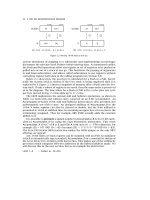
plus hold time to 30 ns. For example, if we take the 74LS377 of Fig. 1.7 used as an
8-bit output port, then its hold time is 5 ns minimum and the propagation delay
time for the 74LS138 from G1 is 26 ns worst-case. Clearly a hazardous race.
To avoid such races we can directly qualify each device which can be written
to by either E, or preferably Q. The 74LS377 octal D flip flop array used as an
8-bit output port is selected at the appropriate address, 6000h in Fig. 1.7, by the
decoder, but the data is only clocked in at the falling edge of Q. This leaves around
1
4
cycle before the data collapses. Where separate enable and clock controls are
not provided, the decoder signal may be gated by a derivative of Q.
RAM chips are more problematical as they need to be enabled until the end of
the cycle when being read from, but cut off early when writing to. This differen-
tiation can be accomplished by qualifying the R/
W signal by Q, producing:
RAM_R/W = R/W
+
Q
which is high irrespective of Q during a Read, and is just Q when writing. As
shown in Fig. 1.8, it is normal to ensure that the RAM will not output data during
a Write-to operation, by driving the RAM's Output_Enable with the complement
of R/
W. The `doctored' RAM_R/W signal may of course be used for as many RAM
chips as are present in the system. It may also be used to replace Q in Fig. 1.7,
having the advantage that the output port cannot be erroneously read.
Care must be taken when interfacing memory chips to choose a device with
a suitable access time. This is especially true for more recent MPUs, which can
run at higher clock rates. The access time for a memory chip is normally given
14 C FOR THE MICROPROCESSOR ENGINEER
Figure 1.6 An elementary address decoding scheme.
MAKING THE CONNECTION 15
Figure 1.7 A simple byte-sized output port.
Figure 1.8 Talking to a 6116 2 kbyte static RAM chip.
16 C FOR THE MICROPROCESSOR ENGINEER
as the duration from the application of a stable address or chip enable until the
activation of the cell to be read from or written to. In the 6116 RAM, this internal
decoding occurs irrespective of the state of the chip enables. Looking first at
RAM interfacing and taking Fig. 1.8 as an example, it is clear that the writing
action is the more critical as this will end earlier at the falling edge of Q. From
Fig. 1.4 we see that we have t
AQ
+ t
QH
less the RAM data setup time. The Hitachi
HM6116AP-20 has a setup requirement of 50 ns and a 200 ns access time, so:
t
AQ
+ t
QH
− 50 ≥ 200
t
AQ
+ t
QH
≥ 250 ns
At 1 MHz, t
AQ
+ t
QH
is 455 ns, but this shrinks to 230 ns for a 2 MHz clock. Thus
a 150 ns access time RAM chip must be used in the latter instance; for example
the Hitachi HM6116AP-15. The 6264 RAM has an access time measured from the
chip select. In this case the address decoder delay must be part of the calculation.
An example of this is given in Section 3.3.
ROM chips are interfaced in a similar fashion, but of course they are read-
only. Referring to the timing diagram of Fig. 1.3, we see that as data from the
ROM must be present t
DSR
before the end of the cycle, we have the relationship
t
cyc
−t
AVS
−t
DSR
≥ t
access
. At 1 MHz this sums to 720 ns, and 380 ns at 2 MHz. Most
of the smaller EPROMs, for example the 2 kbyte Texas Instruments TMSD2516JL,
have 450 ns access times. The TMS2764-25JL is an 8 kbyte 250 ns device and is
therefore suitable for the higher-speed processor.
Rather than qualifying each write-to peripheral by Q, it is possible to enable
the address decoder directly. Thus the decoder should have a lengthy output
pulse when a read is in operation, but be cut short (at the end of Q) when a write
is in progress. This relationship can be written as:
Enable = (R/
W
·
(E
+
Q))
+
(R/W
·
Q)
giving the decoder output waveforms shown in Fig. 1.6(b)(ii) and (iii). To make
use of the two active low
G2A and
G2B 74138 inputs, a little Boolean algebra
yields:
(R/
W
·
E)
+
(R/W
·
Q)
+
(R/W
·
Q)
(R/
W
·
E)
+
Q
·
(R/W
+
R/W)
(R/
W
·
E)
+
Q
(R/
W
+
Q)
·
(Q
+
E) = (G2A)
·
(G2B)
giving the qualifying network of Fig. 1.6(a).
Special-purpose 6800 family peripheral interface devices, such as the PIA of
Fig. 1.9 [13], are designed to work in harmony with older MPU types which only
provide an E signal. They all have an enable input designed to be directly driven
by E, and have data hold time requirements within the 30 ns limit. They must not
be disabled early in the cycle by a Q related signal. This means that 68xx periph-
erals cannot be selected by a modified decoder, such as in Fig. 1.6(a). However,