- Trang chủ >>
- Khoa Học Tự Nhiên >>
- Vật lý
effect of processing parameters on pore structure and thickness of anodic
Bạn đang xem bản rút gọn của tài liệu. Xem và tải ngay bản đầy đủ của tài liệu tại đây (788.97 KB, 7 trang )
Journal of Membrane Science 319 (2008) 192–198
Contents lists available at ScienceDirect
Journal of Membrane Science
journal homepage: www.elsevier.com/locate/memsci
Effect of processing parameters on pore structure and thickness of anodic
aluminum oxide (AAO) tubular membranes
A. Belwalkar
a
, E. Grasing
a
, W. Van Geertruyden
b,∗
, Z. Huang
c
, W.Z. Misiolek
a
a
Institute for Metal Forming, Lehigh University, 5 E. Packer Avenue, Bethlehem, PA 18015, United States
b
EMV Technologies, LLC, 116 Research Drive, Bethlehem, PA 18015, United States
c
Widener University, Kirkbride Hall #365A, Chester, PA 19013, United States
article info
Article history:
Received 23 December 2007
Received in revised form 14 March 2008
Accepted 20 March 2008
Available online 30 March 2008
Keywords:
Nanoporous anodic aluminum oxide
Tubular membrane
Thickness
Interpore distance
Nanohardness
abstract
Nanoporous anodic aluminum oxide (AAO) tubular membranes were fabricated from aluminum alloy
tubes in sulfuric and oxalic acid electrolytes using a two-step anodization process. The membranes were
investigated for characteristics such as pore size, interpore distance and thickness by varying applied volt-
age and electrolyte concentration. Morphology of the membranes was examined using light optical and
scanning electron microscopy and characterized using ImageJ software. Results showed that membranes
having narrow pore size and uniform pore distribution with parallel channel arrays were obtained. The
pore sizes were ranging from 14 to 24 nm and the wall thicknesses as high as 76 m. It was found that the
pore size increased in direct proportion with the applied voltage and inversely with the electrolyte con-
centration while the interpore distance increased linearly with the applied voltage. It was also observed
that increase in acid concentration increased tubular membrane wall thickness that improved mechani-
cal handling. By using anodic alumina technology, robust ceramic tubes with uniformly distributed pore
structure and parallel nanochannels of lengths and sizes practical for industrial applications were reliably
produced in quantity.
© 2008 Elsevier B.V. All rights reserved.
1. Introduction
Nanoporous anodic aluminum oxide (AAO) gained exposure
recently for use as a membrane in applications such as gas sep-
aration, drug delivery, and bone fixation [1–4]. The nanoporous
AAO sheet membrane has been investigated for a potential appli-
cation in hemodialysis by measuring the hydraulic conductivity
and comparing it to those of hollow fiber polymer dialysis mem-
branes [5]. It is known that carefully controlled anodization
of aluminum in an acidic electrolyte produces a thin layer of
dense aluminum oxide, followe d by an ordered array of smaller-
sized nanopores [6]. This self-ordered pore arrangement of the
nanoporous AAO membranes with high pore densities is essential
to maximize permeation and molecular flux across the mem-
brane in a fluid separation application [7]. For example, in a
hemodialysis application, a pore size that is capable of clearing
small (urea, creatinine) and middle (vancomycin, inulin) molec-
ular weight solutes while maintaining large molecular weight
molecules (albumin) is the most desirable. The pore characteris-
tics in terms of pore diameter, interpore spacing and membrane
∗
Corresponding author. Tel.: +1 610 419 4952.
E-mail address: (W. Van Geertruyden).
thickness are controlled by the processing parameters such as for-
mation voltage, anodization time, electrolyte concentration and
temperature [8]. Unlike currently available polymer and cellulose-
based dialysis membrane, the resulting AAO tubular membrane
has uniform pore size, regular pore distribution, high porosity
along with good chemical resistance and temperature stabil-
ity.
The fabrication of AAO sheet membranes and the relationship
between processing parameters and membrane morphology has
been studied previously. Recently, a highly ordered honeycomb
structure was obtained in oxalic acid solution at 40 V [9,10] and
in sulfuric acid at voltages ranging from 20 to 27 V [11].Itwas
reported that pore diameter and interpore spacing was linearly
proportional to the applied voltage [12]. It was also proposed that
self-ordering requires a porosity of 10% which is independent of
the specific anodization conditions and corresponds to aluminum
of about 1.2 [13]. The mechanism by which pores grow is still in
debate, but pore formation models have been developed [14–18].
The pore opening of the bottom layer or barrier layer removal is
also considered an important step towards making a through-hole
porous anodic alumina membrane. Recently, a porous anodic alu-
mina was detached from aluminum substrate and barrier layer was
completely removed by using one-step voltage pulse detachment
method [19,20]. This procedure was reported to be environmentally
0376-7388/$ – see front matter © 2008 Elsevier B.V. All rights reserved.
doi:10.1016/j.memsci.2008.03.044
A. Belwalkar et al. / Journal of Membrane Science 319 (2008) 192–198 193
friendly and efficient as compared to chemical or electrochemical
detachment methods [21].
Highly ordered nanoporous alumina films in sulfuric acid have
also been fabricated through a single step high-field anodization.
The applied potential was raised to the breakdown or burning
potential of the porous anodic alumina films in sulfuric acid and
then increased with the aging of solutions after a long period of
anodization. Self-ordering regime of nanoporous AAO was found
during hard anodization (HA) of aluminum sheets in oxalic acid at
the applied potentials of 100–150 V, more than thrice the voltage
used in conventional oxalic acid anodization (40 V). Extremely rapid
and homogeneous film growth (50–70 mh
−1
) was observed on
the aluminum sheet sample [22,23]. Lower concentrated acid hard-
coating solutions give oxide coatings that are thicker, harder, less
porous, less soluble, and more wear resistant compared to higher
acid concentration anodizing solutions [24].
All the above-discussed techniques of mild anodization and hard
anodization were performed using aluminum sheets. Aluminum
tubes were anodized to form a nanoporous alumina capsules with
a highly uniform and large surface area, which is relatively inex-
pensive device for biofiltration application [4]. Recently, cylindrical
and pentagonal shaped three-dimensional alumina nanotemplates
were fabricated by electrochemical anodization of high-purity alu-
minum wires or tubes [33]. In this research, aluminum tubes were
anodized in 2, 3, 5, 7, 10 and 20 wt% sulfuric acid at 12.5, 15 and 20 V
and, 2.7 wt% oxalic acid at 30 and 40 V, respectively (see Table 1).
The membranes formed under these experimental conditions were
analyzed by measuring their pore size and interpore distance using
ImageJ software. It has been determined that the type of acid elec-
trolyte affected the sheet membrane morphology [25–27]. Keeping
the voltage, temperature and concentration constant, when oxalic
acid was used as the electrolyte, the AAO membranes were found to
have more uniform nanochannels, less embodied anions and better
hexagonal ordering than the membranes formed in sulfuric acid.
These membranes also had larger diameter nanopores than the
ones produced in sulfuric acid [5]. AAO sheets produced in sulfuric
acid electrolyte were also found to have lower flexibility, hardness,
and abrasion resistance than oxalic acid.
A larger tube wall thickness is an advantageous characteristic
for fluid separation application as it helps to maintain the mechan-
ical integrity of the tube during processing, handling and filtration.
Conversely, a smaller tube wall thickness strengthens the rate of
fluid separation by lessening the resistance to waste solute transfer
across the membrane. Ideally, the membrane is as thin as possi-
ble to facilitate filtration while still retaining mechanical integrity.
Such AAO tubular membranes having superior mechanical strength
would be able to withstand high fluid pressures and would be
ideal for potential use in separation applications such as hemodial-
ysis, plasmaspheresis and cryopreservation. In this research, the
mechanical strength was investigated by measuring the membrane
hardness by using nanoindentation technique.
Earlier literature describes thickness as simply a function of total
charge passed to the anode [13,14]. However, others have found that
thickness varies with anode geometry. It was reported that greater
thickness was obtained when oxidation occurred on the inside of
an aluminum tube rather than the outside [25] and this fact was
incorporated in the current research.
2. Materials and methods
2.1. Fabrication of nanoporous AAO tubular membranes
Nanoporous alumina tubular membranes were made from alloy
3003 aluminum (Al
98.6
Mn
1.2
Cu
0.12
) tubes using a two-step anodiza-
tion method. The length, outer diameter, and thickness of the
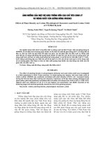
Fig. 1. Experimental setup for anodization of aluminum tubes.
starting tubes were 3.5 cm, 6.35 mm and 700 m, respectively. The
aluminum tubes were anodized first in 2.7 wt% oxalic acid at 30
and 40 V and the smallest pore size obtained was 18.6 ± 2.9 nm at
30 V (Table 2). Since the desired pore size was smaller than the
achieved ones, sulfuric acid with different concentrations was used
to produce membranes with lower pore sizes [5].
Prior to anodizing, each aluminum tube was ultrasonically
cleaned in acetone for 15 min, followed by 5 min of ultrasonic clean-
ing in deionized water. The tube was then electropolished in a
solution made up of phosphoric acid, ethanol and deionized water.
This method is similar to anodization except that it uses much
larger current of the order of 6.5–7 A for approximately 35–45 s.
The electropolishing was followed by another ultrasonic cleansing
in acetone and deionized water. These procedures made the sample
flat, smooth with a shiny surface. The sample was then mounted on
the copper rod that served as the anode. A steel rod was mounted on
the copper rod as cathode. A constant voltage was used throughout
the anodization process. The experimental setup is shown in Fig. 1.
The sample was then anodized at a constant voltage (same as
anodization voltage) for about 5–6 min at 0
◦
C to grow a thin barrier
oxide layer of the order of few nanometers on its surface. An acrylic
polymer was applied on the grown outer barrier oxide layer. This
barrier oxide played a critical role in adhering the applied polymer
thereby protecting the outer aluminum surface from anodizing.
This way, the anodization was carried out only on the inside of the
sample tube [4].
The two-step anodization method was employed to make the
pore structure regular and uniform [28]. The first anodization
Table 1
Experimental electrolyte solutions and applied voltages
Voltage (V) Sulfuric acid concentration (wt%)
12.5 2, 3, 5, 7, 10, and 20
15 3 and 5
20 3
Voltage (V) Oxalic acid concentration (wt%)
30 2.7
40 2.7
194 A. Belwalkar et al. / Journal of Membrane Science 319 (2008) 192–198
(appropriate acid solutions and voltage are in Table 1) was per-
formed at 0
◦
C for approximately 1 h. Following the anodization,
the tube was etched in a mixture of 4 wt% chromic and 8 vol.% phos-
phoric acid at 60
◦
C for about 30 min in a hot water bath to remove
the porous alumina formed during the process. The resulting inner
aluminum surface contained uniform concave nano-array that was
crucial for achieving ordered pore size distribution.
Second anodization was conducted using the same voltage that
was used for first anodization except for longer anodization time
[31]. The typical duration for second anodization ranges from 24
to 36 h. A data acquisition board in conjunction with the LabVIEW
program monitored the current, voltage and temperature in the
anodization cell. The measured current was used to calculate the
charge supplied which came out to be approximately 1800 C for a
10 cm sample.
The tube was filled with deionized water, and the ends were
sealed with parafilm to protect the outer ends and inside of the
tube from getting etched. The polymer protecting the outer surface
was then removed, by acetone. The tube was then dipped in the
solution made up of one part by volume of 0.1 M CuCl
2
solution and
four parts by volume of 10 wt% HCl that removed the unprotected
aluminum in the window.
The tubes were further etched in 4 wt% chromic acid and 8 vol.%
phosphoric acid mixture for approximately 10 min at room tem-
perature to remove the barrier layer from the outer surface. Finally,
the parafilm end-caps were removed to drain the water out and
the tube was thoroughly rinsed with water to remove any acid
that might have reached inner side of the tube via nanochan-
nels.
3. Characterization
Scanning electron microscopy was used to evaluate the pore
diameter and interpore spacing. Mounted AAO specimens were
sputtered with iridium for 4–5 s prior to characterization. Scan-
ning electron microscopy, light optical microscopy and a digitizing
pad were employed to determine the thickness of the AAO tubular
membrane.
Nanoindentation was performed using an atomic force micro-
scope (Digital Instruments, Model MMAFM-02, Nanoscope III,
Version 4.43r8) and Triboscope transducer (Hysitron, 1D SN5-
060-71) with a 150 nm Berkovich tip installed. A trapezoidal load
function with a maximum load of 200 N was entered into the
Triboscope controller software (Triboscope Load Control, Version
4.1.0.0) and used to make the indent on the sample. Between 2 and
5 indents were performed for each tube’s inner diameter surface.
Nanoindentation was performed on tubular membranes manufac-
tured from pure aluminum tubes. These tubes had a smaller inner
diameter (2.5 mm) as compared to the aluminum alloy tubes used
for measurement of pore size. However, the two-step anodization
method was the same as the larger diameter tubes. The Triboscope
software calculated the nanohardness by fitting the power relation
to the unloading curve of the force-deflection data. The nanohard-
ness was then calculate d from the load and the projected contact
area.
Pore size, porosity and interpore distances were measured using
NIH ImageJ software. The pore density can be calculated using the
pore count given by ImageJ, or by determining the pore count by
using the area fraction:
P =
A
p
(/4)D
2
(1)
where P is the pore count, A
p
is the area fraction of pores, and D
is the average pore diameter. The pore density is then determined
by dividing the pore count by the selected area. For example (see
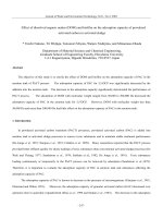
Fig. 2. Schematic illustration showing the measurement of the membrane param-
eters. The pore density is calculated to be 12 pores/a
2
due to the inclusion of four
half pores.
Fig. 2), there are 10 full pores and 4 half pores in the square of side
‘a’. Therefore, the pore density is calculated to be 12 pores per a
2
.
In this investigation, both methods were used to calculated pore
density.
4. Results
The final product demonstrates the transparent AAO tubular
membrane as shown in Fig. 3. Total length of the tubular mem-
brane was 6 cm whereas the effective surface area for filtration was
approximately 4.5–5 cm long. The aluminum ends were not etched
and left as they were before carrying out the first anodization to
aid mechanical handling. The surface and cross-section view of
pore structure for membranes anodized in sulfuric and oxalic acid
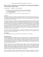
are shown in the SEM images (Fig. 4). Fig. 4(a) and (b) shows the
surface views of the AAO tubular membranes anodized in 5 wt%
sulfuric acid at 12.5 V and in 2.7 wt% oxalic acid at 40 V, respec-
tively. Both membranes demonstrate uniformity in pore size and
distribution. Thickness of the AAO tubular membrane anodized in
20 wt% sulfuric acid at 12.5 V was measured to be approximately
76 m as shown in Fig. 4(c), the aspect ratio being as high as about
3800. This result demonstrated that a very high value of aspect
ratio is achievable by using the procedure described in Section 2
(see Table 3 for parameters used). Fig. 4(d) depicts a higher mag-
nification cross-sectional view of a tubular membrane anodized
in 3 wt% sulfuric acid at 12.5 V. The figure shows pores starting at
one surface (inner), extending themselves parallel to each other
and ending at the other surface (outer). For example, the molecules
once pass into one end (inner) of the pore would only come out
from the other end (outer) of the pore without diffusing out from
the middle of the pore-tunnel.
The relationship of membrane thickness and hardness with the
experimental parameters was propose d. It was suggested that the
Fig. 3. Nanoporous AAO tubular membrane in its final form.
A. Belwalkar et al. / Journal of Membrane Science 319 (2008) 192–198 195
Fig. 4. SEM images of surface view of nanoporous AAO tubular membrane anodized in (a) 5 wt% sulfuric acid at 12.5 V and (b) 2.7 wt% oxalic acid at 40 V. Cross-section view
of AAO tubular membrane anodized in (c) 20 wt% sulfuric acid at 12.5 V and (d) 3 wt% sulfuric acid at 12.5 V. Parallel nanochannels are depicted in (d).
Table 2
Pore size of AAO tubular membranes produced by 2.7 wt% oxalic acid at 30 and 40 V
at 0
◦
C
Concentration of oxalic acid (wt%) Pore size (nm), voltage (V)
30 40
2.7 18.6 ± 2.9 33.6 ± 7.6
mechanical strength of the nanoporous AAO tubular membrane
is proportional to both the measured thickness and hardness val-
ues.
4.1. Pore size
As shown in Fig. 4(a) and (b), the average pore size of the tubu-
lar membranes were around 19 and 33 nm, when anodized in 5 wt%
sulfuric acid at 12.5 V and 2.7 wt% oxalic acid at 40 V, respectively.
Tables 2 and 3 summarize the data of pore size with respect to
voltage and concentration for oxalic acid and sulfuric acid, respec-
tively. As shown in Table 2, when the voltage increased from 30
to 40 V, the pore size increased from 18.6 ± 2.9 to 33.6 ± 7.6 nm,
respectively. Similar behavior occurred when the samples were
anodized in sulfuric acid at different concentrations. When volt-
Table 3
Pore size of AAO tubular membranes produced by 3, 5, 7, 10 and 20 wt% sulfuric acid
at 12.5, 15 and 20 V at 0
◦
C
Concentration of sulfuric acid (wt%) Pore size (nm), voltage (V)
12.5 15 20
3 19.9 ± 1.9 21.6 ± 1.8 24 ± 2.5
5 19.1 ± 1.9 21.4 ± 0.8
719± 0.5
10 18.4 ± 5.6
20 13.7 ± 7.8
Table 4
Interpore distance of AAO tubular membranes produced by 3, 5, 7, 10 and 20 wt%
sulfuric acid at 12.5, 15 and 20 V at 0
◦
C
Concentration of sulfuric acid (wt%) Interpore distance (nm), voltage (V)
12.5 15 20
3 32.7 ± 2.8 36.4 ± 1.6 45.4 ± 8
531.9± 3.2 38.8 ± 0.4
731.8± 2.9
10 32.6 ± 4.7
20 29.9 ± 2.4
age increased from 12.5 to 20 V for the samples anodized in 3 wt%
sulfuric acid, the pore size increased from 19.9 ± 1.9to24± 2.5 nm,
respectively. In case of samples anodized in 5 wt% sulfuric acid, the
pore size increased from 19.1 ± 1.9to21.4± 0.8 nm, when the volt-
age increased from 12.5 to 15 V. When the concentration of sulfuric
acid increased from 3 to 20 wt% for the samples anodized at 12.5 V,
the pore size decreased from 19.9 ± 1.9to13.7± 7.8 nm. The pore
size of the samples anodized at 15 V decreased from 21.6 ± 1.8 in
3 wt% sulfuric acid to 21.4 ± 0.8 nm in 5 wt% sulfuric acid.
4.2. Interpore distance
The interpore distances of nanoporous AAO tubular membranes
anodized in sulfuric and oxalic acid are tabulated in Tables 4 and 5,
respectively. In case of samples anodized in 3 wt% sulfuric acid,
Table 5
Interpore distances for AAO tubular membranes anodized by 2.7% oxalic acid at 30
and 40 V at 0
◦
C
Concentration of oxalic acid (wt%) Interpore distance (nm), voltage (V)
30 40
2.7 65.1 ± 6.5 80.5 ± 3.2
196 A. Belwalkar et al. / Journal of Membrane Science 319 (2008) 192–198
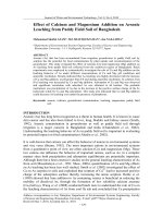
Fig. 5. Variation of AAO tubular membrane thickness with respect to anodization
time.
when the voltage increased from 12.5 to 20 V, the interpore distance
increased from 32.7 ± 2.8 to 45.4 ± 8 nm. The interpore distance
remained constant at an average value of 31.8 ± 1.1 nm for differ-
ent concentrations of sulfuric acid at 12.5 V. A similar behavior
occurred with samples anodized at 15 V in 3 and 5 wt% sulfuric
acid where the average interpore distance was 37.6 ± 1.7 nm. In
the case of samples anodized in 2.7 wt% oxalic acid, the interpore
distances were 65.1 ± 6.5 and 80.5 ± 3.2 nm at 30 and 40 V, respec-
tively.
4.3. Thickness
Fig. 5 shows the graph that depicts the tubular membrane
wall thickness as a function of second anodization time for 2,
10 and 20 wt% sulfuric acid concentration. AAO tubular mem-
brane thickness increased with increase in anodization time. As
the anodization time increased from 2 to 32 h, the thickness of
the membrane anodized in 20 wt% sulfuric acid increased from
8.6 ± 1.8to76± 7 m. Similar increase in membrane thickness was
observed in case of samples anodized in 10 and 2 wt% sulfuric
acid with respect to anodization time, where the membrane thick-
ness increased from 13.7 ± 3.7 to 47.5 ± 2.2 m and from 5.5 ± 0.2
to 10.3 ± 1.3 m, respectively. It was also observed that increase
in concentration of sulfuric acid increased the membrane thick-
ness.
Fig. 6. The variation of nanohardness as a function of anodization time.
4.4. Hardness
The average nanohardness of select AAO tubular membrane
samples is shown in Fig. 6 as a function of second anodization
time. Samples anodized in 2, 10 and 20 wt% sulfuric acid are pre-
sented. It was observed that the membrane hardness decreased as
the thickness increased with respect to time.
5. Discussion
5.1. Pore size
It was found that processing parameters can have a dramatic
effect on pore characteristics. The results in Tables 2 and 3 indicated
that the pore size of nanoporous AAO tubular membranes increased
with increase in applie d voltage irrespective of the electrolyte used.
It is suggested that the pore formation is accompanied by volume
expansion during the oxide formation at the metal-oxide interface.
This volume expansion is given by Pilling–Bedworth Ratio (PBR)
which is expressed as
PBR =
Volume of oxide produced
Volume of metal consumed
(2)
Due to volume expansion, the oxide is pushed in tangential
and in upward direction moving the oxide walls upward thereby
increasing the height of the pore wall. Since higher voltage is
associated with higher current densities and hence higher vol-
ume expansion, more oxide is pushed in tangential and in upward
direction. The pore walls are squeezed more thereby forming larger
pores.
Table 2 also indicated that the pore size decreased with increase
in sulfuric acid concentration at the same voltage. Oxide growth
rate and its rate of dissolution partially depended upon concen-
tration of sulfuric acid. Higher electrolyte concentration increased
oxide dissolution and oxidation growth. With faster oxidation and
dissolution, the pore size decreased. Thus, pores were smaller with
20% than 3% sulfuric acid.
5.2. Interpore distance
Tables 4 and 5 indicated that the interpore distance increased
with increase in the applied voltage. It is well known that for
AAO, the interpore distance D
int
is linearly proportional to the
applied voltage V with proportionality constant , of approximately
≈ 2.5 nm/V
D
int
= V (3)
Table 4 indicated that the average interpore distance of the sam-
ple tubes anodized in 3% sulfuric acid at 12.5, 15 and 20 V were
32.7 ± 2.8, 36.4 ± 1.6 and 45.4 ± 8 nm, respectively. Using expres-
sion (3), the interpore distances at voltage 12.5, 15 and 20 V are
calculated to be 31.5, 37.5 and 50 nm, respectively. Thus, it is
observed that the interpore distances measured by conducting the
experiments are in agreement with the interpore distance calcu-
lated using the proportionality constant .
From Table 4, it is also observed that the average interpore
distance remains constant even when there is a change in the con-
centration of the electrolyte, as can be seen from the interpore
distance values of the AAO membranes yielded from different con-
centration of sulfuric acid at 12.5 V.
5.3. Thickness
Membrane thickness greatly affects the ability of the AAO tubu-
lar membranes to be handled, as well as decreases the probability
A. Belwalkar et al. / Journal of Membrane Science 319 (2008) 192–198 197
Table 6
AAO growth rate for each sulfuric acid electrolyte concentration
Acid concentration (wt%) Anodic aluminum oxide growth rate (m/h)
2 0.318
10 1.272
20 2.148
of fracture during the fabrication process. Tube wall thicknesses
obtained during this investigation ranged from 5 to 76 m. Simi-
larly, tube thicknesses in the literature range from 35 to 200 m
[15].
It was suggeste d that the dissolution of AAO in electrolyte is
‘field-assisted’, or strongly dependent on voltage potential [14].
Fig. 5 confirms the field-assisted nature of the AAO dissolution,
as increasing the acid concentration does not increase aluminum
oxide dissolution. In fact, the highest acid concentration exhibits
the largest membrane thickness, due to its high oxide growth rate,
shown in Table 6. This is most likely caused by the variation in elec-
trolyte conductivity, as noted by the current density experiments.
The increased current gives greater impetus for greater volume
expansion thereby pushing more oxide up the walls resulting in
thicker membranes.
Although Fig. 5 shows mostly a linear relationship between
anodization time and thickness, a limiting thickness is evident
with prolonged second anodization, though previous literature has
suggested that the membrane thickness is proportional to total
current passed to the anode [15]. This suggests that the mem-
brane thickness is dictated by dynamic equilibrium of oxidation
and chemical dissolution. The dynamic equilibrium of the oxide
formation (highly dependent on the acid concentration and avail-
ability of oxygen ions) and dissolution (relatively constant due
to its field-assistant nature) causes a characteristic limiting thick-
ness. Aluminum tubes anodized in 3 wt% sulfuric acid electrolyte
concentrations exhibit characteristic limiting thicknesses. The lim-
iting wall thickness in 3 wt% sulfuric acid is approximately 37 m
and occurs at 24 h. This is due to their higher oxide growth rates
which require longer anodization times to attenuate [32].Itis
believed that with second anodization times longer than 32 h, tubes
anodized in 10 and 20 wt% sulfuric acid will also exhibit character-
istic limiting thicknesses.
The dissolution of the AAO limits the tubular membrane thick-
ness and also affects the nanohardness of the tubular membrane.
Fig. 6 confirms the existence of pore wall softening due to exposure
to the acid electrolyte, as the nanohardness is inversely propor-
Fig. 7. Average current density during the second anodization as a function of sul-
furic acid concentration.
tional to second anodization time. The pore wall softening was
described previously in terms of a microcrystalline model, in which
the acid electrolyte attacks the anion-rich hydrous region between
the fine-grained anhydrous aluminum oxide [29]. The pore wall
softening causes a decrease in nanohardness. The decrease in
nanohardness confirms the domination of dissolution rate as the
anodization continues.
As mentioned previously, the increase in oxidation rate is
believed to be caused by an increase in conductivity. The increased
conductivity increases the availability of oxygen ions and thus the
oxide growth rate. The experimental results for current density,
as shown in Fig. 7, are in good agreement with the literature [30],
which illustrates a linearly proportional relationship between 0 and
30 wt% sulfuric acid. Also shown in Table 6, the highest sulfuric acid
concentration, 20 wt%, had the largest oxide growth rate.
6. Conclusions
In this study, AAO tubular membranes were produced under
various experimental conditions and the pore size, interpore dis-
tance, thickness and hardness were measured. The voltage affected
the pore size: the pore size increased with increase in the applied
voltage and decreased with increase in acid concentration. Concen-
tration of the acids also influenced the pore size in a way that higher
acid concentration increased the rate of oxidation than dissolution
thereby decreasing the pore size.
Interpore distance increased with respect to the applied voltage
by the proportionality constant , of approximately ≈ 2.5 nm/V.
While the applied voltage was kept constant, the interpore distance
remained at constant value even when the concentration of sulfuric
acid was changed. It was confirmed that the interpore distance was
function of the applied voltage alone.
The rate of oxide growth was found to be greater in higher acid
concentrations. It was proposed that this was caused by the con-
ductivity of the acid, as higher acid concentrations resulted in larger
current densities. The field-assisted nature of the AAO dissolution
was confirmed.
The membrane thickness was found to be proportional to the
concentration of acidic electrolyte. However, it was also observed
that prolonged second anodization time eventually reduced mem-
brane thickness. This suggests that the membrane thickness must
be described by the dynamic equilibrium of the oxidation and dis-
solution rates. It is proposed that the attenuation of the oxidation
rate and the resulting limiting thickness is due to depletion of oxy-
gen ions in the acid electrolyte solution. As each acid concentration
exhibited a different oxidation rate, it is proposed that each acid
concentration also displays a characteristic limiting thickness at
a specific time, determined by the equilibrium of the oxidation
rate and field-assisted dissolution rate. Besides limiting the thick-
ness, the dissolution also affects the nanohardness of AAO tubular
membranes. It was observed that the nanohardness was inversely
proportional to the anodization time.
Acknowledgements
Funding for this research was provided by the National Insti-
tutes of Health Grant #1 R41 DK074254-01 and the Pennsylvania
Infrastructure Technology Authority Grant# 766-07. Partial support
for Dr. Wojciech Z. Misiolek has been provided by the Loewy Family
Foundation.
References
[1] G. Gorokh, A. Mozalev, D. Solovei, V. Khatko, E. Llobet, X. Correig, Anodic
formation of low-aspect-ratio porous alumina films for metal-oxide sensor
application, Electrochim. Acta 52 (2006) 1771–1780.
198 A. Belwalkar et al. / Journal of Membrane Science 319 (2008) 192–198
[2] E. Briggs, A. Walpole, P. Wilshaw, M. Karlsson, E. Palsgard, Formation of highly
adherent nano-porous alumina on Ti-based substrates: a novel bone implant
coating, J. Mater. Sci. Mater. Med. 15 (2004) 1021–1029.
[3] P.A.M. Darder, M. Hernandez-Velez, E. Manova, E. Ruiz-Hitzky, Encapsulation
of enzymes in alumina membrane of controlled pore size, Thin Solid Films 495
(2005) 321–326.
[4] G. Dawai, V. Yadavalli, M. Paulose, M. Pishko, C. Grimes, Controlled molecular
release using nanoporous alumina capsules, therapeutic micro and nanotech-
nology, Biomed. Microdevices 5 (2003) 75–80.
[5] Z. Huang, W. Zhang, J.Yu, D. Gao, Nanoporous alumina membrane forenhancing
hemodialysis, J. Med. Devices vol.1 (2007) 79–83.
[6] R.S. Alwitt, J. Xu, Stresses in sulfuric acid anodized coatings on aluminum, J.
Electrochem. Soc. 140 (1993) 1241–1246.
[7] W. Chen, J. Yuan, X. Xia, Characterization and manipulation of the electroos-
motic flow in porous anodic alumina membranes, Anal. Chem. 77 (2005)
8102–8108.
[8] A. Belwalkar, Experimental study of nanoporous ceramic tubes for potential
application inhemodialysis, Mechanical Engineering, M.S.Thesis,Widener Uni-
versity, Chester, PA, 127, 2006.
[9] H. Masuda, K. Fukuda, Ordered metal nanohole arrays made by a two-step
replication of honeycomb structures of anodic alumina, Science 268 (1995)
1466.
[10] H. Masuda, M. Satoh, Fabrication of gold nanodot array using anodic porous
alumina as an evaporation mask, Jpn. J. Appl. Phys. 35 (1996) L126.
[11] H. Masuda, F. Hasegwa, Self-ordering of cell arrangement of anodic porous
alumina formed in sulfuric acid solution, J. Electrochem. Soc. 144 (5) (1997)
L127–L130.
[12] J.P. O’Sullivan, G.C. Wood, The morphology and mechanism of formation of
porous anodic films on aluminum, Proc. R. Soc. Lond. B Biol. Sci. Math. Phys. Sci.
317 (1970) 511–543.
[13] K. Nielsch, J. Choi, K. Schwirn, R. Wehrspohn, U. Gosele, Self ordering regimes
of porous alumina: 10% porosity rule, Nano Lett. 2 (7) (2002) 677–680.
[14] J.W. Diggle, T.C. Downie, C.W. Goulding, Processes involved in reattainment
of steady-state conditions for the anodizing of aluminum following formation
voltage changes, J. Electrochem. Soc.: Electrochem. Sci. (1969) 737–740.
[15] S.J. Garcia-Vergara, P. Skeldon, G.E. Thompson, H. Habazaki, A flow model of
porous anodic film growth aluminum, Electrochim. Acta 52 (2006) 681–687.
[16] N. Itoh, K. Kato, T. Tsuji, M. Hongo, Preparation of tubular anodic aluminum
oxide membrane, J. Membr. Sci. 117 (1996) 189–196.
[17] T.P. Hoar, N.F. Mott, A mechanism for the formation of porous anodic oxide films
on aluminium, J. Phys. Chem. Solids 9 (1959) 97.
[18] J. Siejka, C. Ortega, An O-18 study of field-assisted pore formation in compact
anodic oxide films on Al, J. Electrochem. Soc. 124 (1977) 883.
[19] J.H. Yuan, F.Y. He, D.C. Sun, X.H. Xia, A simple method for preparation of
through-hole porous anodic alumina membrane, Chem. Mater. 16 (2004)
1841–1844.
[20] J.H. Yuan, W. Chen, R.J. Hui, Y.L. Hu, X.H. Xia, Mechanism of one-step voltage
pulse detachment of porous anodic alumina membranes, Electrochim. Acta 51
(2006) 4589–4595.
[21] J.H. Yuan, W. Chen, J.S. Wu, X.H. Lin, X.H. Xia, An environment friendly electro-
chemical detachment method for porous anodic alumina, J. Electroanal. Chem.
600 (2007) 257–264.
[22] S. Chu, K. Wada, S. Inoue, M. Isogai, A . Yasumori, Fabrication of ideally ordered
nanoporous alumina films and integrated alumina nanotubule arrays by high-
field anodization, Adv. Mater. (2005) 2115–2119.
[23] W. Lee, R. Ji, U. Gosele, K. Nielsch, Fast fabrication of long-range ordered
porous alumina membranes by hard-anodization, Nat. Mater. 5 (2006) 741–
747.
[24] S. Samuel, Determination of sulfuric acid, oxalic acid, and their matrix effects
in aluminum anodizing solutions by ion chromatography, Defense Technical
Information Center, Accession Number ADA197734, 1988.
[25] N.N.T. Itoh, T. Tsuji, M. Hongo, Preparation of a tubular anodic aluminum oxide
membrane, J. Membr. Sci. 117 (1998) 189–196.
[26] G. Patermarkis, K. Masavetas, Aluminum anodising in oxalate and sulphate
solutions. Comparison of chronopotentiometric and overall kinetic response
of growth mechanism of porous anodic films, J. Electroanal. Chem. 588 (2006)
179–189.
[27] Y. Sui, J.M. Saniger, Characterization of anodic porous alumina by AFM, Mater.
Lett. 48 (2001) 127–136.
[28] O. Jessensky, F. Muller, U. Gosele, Self-organized formation of hexagonal
pore arrays in anodic alumina, J. Electrochem. Soc. 72 (10) (1998) 1173–
1175.
[29] C.E. Alvey, M.A. Brett, G.C. Wood, The mechanical properties of porous anodic
aluminum oxide films on aluminum, in: Proceedings of the Third South
African Corrosion Conference, CSIR Conference Centre, Pretoria, South Africa,
1980.
[30] Company Literature, Sulfuric Acid Measurement, Foxboro, Foxboro, MA,
2005.
[31] Y. Kobayashi, K. Iwasaki, T. Kytonai, A. Tomita, Preparation of tubular alu-
mina membrane with uniform straight channels by anodic oxidation process,
J. Mater. Sci. 31 (1996) 6185–6187.
[32] C. Cherki, J. Siejka, Study by nuclear microanalysis and O18 tracer techniques
of the oxygen transport processes and the growth laws for porous anodic oxide
layers on aluminum, J. Electrochem. Soc. 120 (1973) 784.
[33] B.Y. Yoo, R.K. Hendricks, M. Ozkan, N.V. Myung, Three-dimensional alumina
nanotemplate, Electrochim. Acta 51 (2006) 3543–3550.