electric power substations engineering (17)
Bạn đang xem bản rút gọn của tài liệu. Xem và tải ngay bản đầy đủ của tài liệu tại đây (1.99 MB, 25 trang )
15
-1
0-8493-1703-7/03/$0.00+$1.50
© 2003 by CRC Press LLC
15
Substation
Communications
15.1 Introduction
15
-1
15.2 Supervisory Control and Data Acquisition (SCADA)
Historical Perspective
15
-2
15.3 SCADA Functional Requirements
15
-4
15.4 SCADA Communication Requirements
15
-4
15.5 Components of a SCADA System
15
-5
15.6 SCADA Communication Protocols: Past, Present,
and Future
15
-6
General Considerations • DNP • IEC 870-5 • UCA
1.0 • ICCP • UCA 2.0 • IEC 61850 • Continuing Work
15.7 The Structure of a SCADA Communications
Protocol
15
-9
15.8 Security for Substation Communications
15
-11
General Considerations • SCADA Security Attacks • Security
by Obscurity • SCADA Message Data Integrity
Checking • Encryption • Denial of Service
15.9 Electromagnetic Environment
15
-14
15.10 Communications Media
15
-15
ARDIS (Advanced Radio Data Information Service) • Cellular
Telephone Data Services • Digital Microwave • Fiber
Optics • Hybrid Fiber Coax • ISDN • Digital Subscriber
Loop (DSL) • Telephone Lines: Leased and Dial-Up • MAS
Radio • Mobile Computing Infrastructure • Mobile
Radio • Mobitex Packet Radio • Paging Systems • Power-
Line Carrier • Satellite Systems • Short Message System
(SMS) • Spread-Spectrum Radio and Wireless LANs • T1
and Fractional T1
15.11 Additional Information
15
-22
Useful Web Sites • Relevant Standards
15.1 Introduction
Modern electric power systems have been dubbed “the largest machine made by mankind” because they
are both physically large – literally thousands of miles in dimension – and operate in precise synchronism.
In North America, for example, the entire West Coast, everything east of the Rocky Mountains, and the
state of Texas operate as three autonomous interconnected “machines.” The task of keeping such a large
machine functioning without breaking itself apart is not trivial. The fact that power systems work as
reliably as they do is a tribute to the level of sophistication that is built into them. Substation commu-
nication plays a vital role in power system operation. This chapter provides a brief historical overview
of substation communication, followed by sections that:
Daniel E. Nordell
Consulting Engineer
1703_Frame_C15.fm Page 1 Monday, May 12, 2003 8:38 PM
© 2003 by CRC Press LLC
15
-2
Electric Power Substations Engineering
• Review functional and communication requirements
• Examine the components of both traditional and emerging supervisory control and data acqui-
sition (SCADA) systems
• Review the characteristics of past, present, and future substation communication protocols
• Review the role of standards for substation communication
• Discuss the electromagnetic environment that substation communication devices must withstand
• Discuss security aspects of substation communications
• Discuss communication media options for substation communications
15.2 Supervisory Control and Data Acquisition (SCADA)
Historical Perspective
Electric power systems as we know them began developing in the early 20th century. Initially, generating
plants were associated only with local loads that typically consisted of lighting and electric transportation.
If anything in the system failed — generating plant, power lines, or connections — the lights would quite
literally be “out.” Customers had not yet learned to depend on electricity being nearly 100% reliable, so
outages, whether routine or emergency, were taken as a matter of course.
As reliance on electric power grew, so did the need to find ways to improve reliability. Generating
stations and power lines were interconnected to provide redundancy, and higher voltages were used for
longer distance transportation of electricity. Points where power lines came together or where voltages
were transformed came to be known as “substations.” Substations often employed protective devices to
allow system failures to be isolated so that faults would not bring down the entire system, and operating
personnel were often stationed at these important points in the electrical system so that they could
monitor and quickly respond to any problems that might arise. They would communicate with central
system dispatchers by any means available — often by telephone — to keep them apprised of the condition
of the system. Such “manned” substations were normative throughout the first half of the 20th century.
As the demands for reliable electric power became greater and as labor became a more significant part
of the cost of providing electric power, technologies known as “supervisory control and data acquisition,”
or SCADA for short, were developed to allow remote monitoring and even control of key system
parameters. SCADA systems began to reduce and even eliminate the need for personnel to be on-hand
at substations.
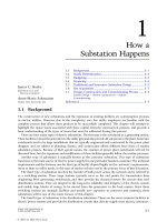
Early SCADA systems provided remote indication and control of substation parameters using tech-
nology borrowed from automatic telephone switching systems. As early as 1932, Automatic Electric was
advertising “remote-control” products based on its successful line of “Strowger” telephone switching
apparatus (Figure 15.1). Another example (used as late as the 1960s) was an early Westinghouse REDAC
system that used telephone-type electromechanical relay equipment at both ends of a conventional
twisted-pair telephone circuit. Data rates on these early systems were slow. Data were sent in the same
manner as rotary-dial telephone commands at 10 bps, so only a limited amount of information could
be passed using this technology.
Early SCADA systems were built on the notion of replicating remote controls, lamps, and analog
indications at the functional equivalent of pushbuttons, often placed on a mapboard for easy operator
interface. The SCADA masters simply replicated, point for point, control circuits connected to the remote
(slave) unit.
During the same time frame as SCADA systems were developing, a second technology — remote
teleprinting, or “Te l e t y p e ” — was coming of age, and by the 1960s had gone through several generations
of development. The invention of a second device — the “modem” (MOdulator/DEModulator) —
allowed digital information to be sent over wire pairs that had been engineered to only carry the electronic
equivalent of human voice communication. With the introduction of digital electronics it was possible
to use faster data streams to provide remote indication and control of system parameters. This marriage
1703_Frame_C15.fm Page 2 Monday, May 12, 2003 8:38 PM
© 2003 by CRC Press LLC
Substation Communications
15
-3
of Teletype technology with digital electronics gave birth to remote terminal units (RTUs), which were
typically built with discrete solid-state electronics and could provide remote indication and control of
both discrete events and analog voltage and current quantities.
Beginning also in the late 1960s and early 1970s, technology leaders began exploring the use of small
computers (minicomputers at that time) in substations to provide advanced functional and communi-
cation capability. But early application of computers in electric substations met with industry resistance
because of perceived and real reliability issues.
The introduction of the microprocessor with the Intel 4004 in 1971 (see
for a fascinating history) opened the door for increasing sophistication in RTU design that is still
continuing today. Traditional point-oriented RTUs that reported discrete events and analog quantities
could be built in a fraction of the physical size required by previous discrete designs. More intelligence
could be introduced into the device to increase its functionality. For the first time RTUs could be built
to report quantities in engineering units rather than as raw binary values. One early design developed
at Northern States Power Company in 1972 used the Intel 4004 as the basis for a standardized environ-
mental data acquisition and retrieval (SEDAR) system that collected, logged, and reported environmental
information in engineering units using only 4 kilobytes of program memory and 512 nibbles (half-bytes)
of data memory.
While the microprocessor offered the potential for greatly increased functionality at lower cost, the
industry also demanded very high reliability and long service life measured in decades, conditions that
were difficult to achieve with early devices. Thus the industry was slow to accept the use of microprocessor
technology in mission-critical applications. By the late 1970s and early 1980s, integrated microprocessor-
based devices were introduced, and these came to be known as intelligent electronic devices, or IEDs.
FIGURE 15.1
Electrical World advertisement, October 31, 1932.
1703_Frame_C15.fm Page 3 Monday, May 12, 2003 8:38 PM
© 2003 by CRC Press LLC
15
-4
Electric Power Substations Engineering
Early IEDs simply replicated the functionality of their predecessors — remotely reporting and con-
trolling contact closures and analog quantities using proprietary communication protocols. Increasingly,
IEDs are also being used to convert data into engineering unit values in the field and to participate in
field-based local control algorithms. Many IEDs are being built with programmable logic controller (PLC)
capability and, indeed, PLCs are being used as RTUs and IEDs to the point that the distinction between
these different types of smart field devices is rapidly blurring.
Early SCADA communication protocols were usually proprietary and were also often kept secret from
the industry. A trend beginning in the mid-1980s has been to minimize the number of proprietary
communication practices and to drive field practices toward open, standards-based specifications. Two
noteworthy pieces of work in this respect are the International Electrotechnical Commission (IEC) 870-
5 family of standards and the IEC 61850 standard. The IEC 870-5 work represents the pinnacle of the
traditional point-list-oriented SCADA protocols, while the IEC 61850 standard is the first of an emerging
approach to networkable, object-oriented SCADA protocols based on work started in the mid-1980s by
the Electric Power Research Institute (EPRI) that became known as the Utility Communication Archi-
tecture (UCA).
15.3 SCADA Functional Requirements
Design of any system should always be preceded by a formal determination of the business and corre-
sponding technical requirements that drive the design. Such a formal statement is known as a “functional
requirements specification.” Functional requirements capture the intended behavior of the system. This
behavior can be expressed as services, tasks, or functions the system is required to perform.
In the case of SCADA, the specification contains such information as system status points to be
monitored, desired control points, and analog quantities to be monitored. It also includes identification
of acceptable delays between when an event happens and when it is reported, required precision for
analog quantities, and acceptable reliability levels. The functional-requirements analysis will also include
a determination of the number of remote points to be monitored and controlled. It should also include
identification of communication stakeholders other than the control center, such as maintenance engi-
neers and system planners who may need communication with the substation for reasons other than
real-time operating functionality.
The functional-requirements analysis should also include a formal recognition of the physical, elec-
trical, communications, and security environment in which the communications are expected to operate.
Considerations here include recognizing the possible (likely) existence of electromagnetic interference
from nearby power systems, identifying available communications facilities, identifying functionally the
locations between which communications are expected to take place, and identifying potential commu-
nication security threats to the system.
It is sometimes difficult to identify all of the items to be included in the functional requirements. A
technique that has been found useful in the industry is to construct a number of example “use cases”
that detail particular individual sets of requirements. Aggregate use cases can form a basis for a more
formal collection of requirements.
15.4 SCADA Communication Requirements
After the functional requirements have been articulated, the corresponding architectural design for the
communication system can be set forth. Communication requirements include those elements that must
be considered in order to meet the functional requirements. Some elements of the communication
requirements include:
• Identification of communication traffic flows — source, destination, quantity
• Overall system topology, e.g., star, mesh
• Identification of end-system locations
1703_Frame_C15.fm Page 4 Monday, May 12, 2003 8:38 PM
© 2003 by CRC Press LLC
Substation Communications
15
-5
• Device and processor capabilities
• Communication session, dialog characteristics
• Device addressing schemes
• Communication network traffic characteristics
• Performance requirements
• Timing issues
• Reliability, backup, failover
• Application service requirements
• Application data formats
• Operational requirements (directory, security, and management of the network)
• Quantification of electromagnetic-interference-withstand requirements
15.5 Components of a SCADA System
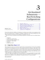
Traditional SCADA systems grew up with the notion of a SCADA master and a SCADA slave (remote).
The implicit topology was that of a “star” or “spoke and hub,” with the master in charge. In the historical
context, the master was a hardwired device with the functional equivalent of indicator lamps and
pushbuttons (Figure 15.2).
Modern SCADA systems employ a computerized SCADA master in which the remote information is
either displayed on an operator’s computer terminal or made available to a larger energy management
system (EMS) through networked connections. The substation RTU is either hardwired to digital, analog,
and control points, or it frequently acts as a sub-master or data concentrator in which connections to
intelligent devices inside the substation are made using communication links. Most interfaces in these
systems are proprietary, although in recent years standards-based communication protocols to the RTUs
have become popular. In these systems, if other stakeholders such as engineers or system planners need
FIGURE 15.2
Traditional SCADA system topology.
Central
SCADA
Master
Proprietary
Interfaces
SCADA Remotes
Substations / Field Equipment
Breaker
Relay
Voltage
Current
Substation
1703_Frame_C15.fm Page 5 Monday, May 12, 2003 8:38 PM
© 2003 by CRC Press LLC
15
-6
Electric Power Substations Engineering
access to the substation for configuration or diagnostic information, then separate (often ad hoc) pro-
vision is usually made using technologies such as dial-up telephone circuits.
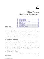
With the introduction of networkable communication protocols, typified by the IEC 61850 series of
standards, it is now possible to simultaneously support communication with multiple clients located at
multiple remote locations. Figure 15.3 shows how such a network might look. This configuration will
support clients located at multiple sites simultaneously accessing substation devices for applications as
diverse as SCADA, device administration, system fault analysis, metering, and system load studies.
SCADA systems, as traditionally conceived, report only real-time information. Figure 15.3 shows
another function that can be included in a modern SCADA system: that of an historian which time-tags
each change of state of selected status parameters or each change (beyond a chosen deadband) of analog
parameters and then stores this information in an efficient data store that can be used to rebuild the
system state at any selected time for system performance analyses.
15.6 SCADA Communication Protocols: Past, Present, and
Future
15.6.1 General Considerations
As noted in the section on SCADA history, early SCADA protocols were built on electromechanical
telephone switching technology. Signaling was usually done using pulsed direct-current signals at a data
rate on the order of 10 pulses per second. Analog information could be sent using current loops that
could provide constant current independent of circuit impedance while also communicating over large
distances (thousands of feet) without loss of signal quality. Control and status points were indexed using
FIGURE 15.3
Networked SCADA communications.
Corporate
Environment
Corp
Intranet
Operations
Intranet
Substations / Field Equipment
Networked Communications
Historian
Firewall
DB Server(s)
External
Firewall
Open
UIB Interfaces
Open
Interfaces
Operations applications
Corporate applications
Operations
Environment
1703_Frame_C15.fm Page 6 Monday, May 12, 2003 8:38 PM
© 2003 by CRC Press LLC
Substation Communications
15
-7
assigned positions in the pulse train. Communications security was assured by means of repetition of
commands or such mechanisms as “arm” and “execute” for control.
With the advent of digital communications (still precomputer), higher data rates were possible. Analog
values could be sent in digital form using analog-to-digital converters, and errors could be detected using
parity bits and block checksums. Control and status points were assigned positions in the data blocks,
which then needed to be synchronized between the remote and master devices. Changes of status were
detected by means of repetitive “scans” of remote devices, with the scan rate being a critical system design
factor. Communications integrity was assured by the use of more sophisticated block ciphers, including
the cyclical redundancy check, which could detect both single- and multiple-bit errors in communica-
tions. Control integrity was ensured by the use of end-to-end select-check-operate procedures. The
manufacturers (and sometimes the users) of these early SCADA systems would typically define their own
communication protocol, and the industry became known for the large number of competing practices.
Computer-based SCADA master stations, followed by microprocessor-based remote terminal units,
continued the traditions set by the early systems of using points-list-based representations of control and
status information. Newer, still proprietary, communication protocols became increasingly sophisticated
in the types of control and status information that could be passed. The notion of “report by exception”
was introduced, in which a remote terminal could report “no change” in response to a master-station
poll, thus conserving communication resources and reducing average poll times.
By the early 1980s, the electric utility industry enjoyed the marketplace confusion brought on by
approximately 100 competing proprietary SCADA protocols and their variants. With the rising under-
standing of the value of building on open practices, a number of groups began to approach the task of
bringing standard practices to bear on utility SCADA practices.
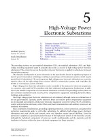
As shown in Figure 15.4, a number of different groups are often involved in the process of reaching
consensus on standard practices. The process reads from the bottom to the top, with the “international
standards” level the most sought-after and also often the most difficult to achieve. The process typically
starts with practices that have proved to be useful in the marketplace but are, at least initially, defined
and controlled by a particular vendor or, sometimes, end user. The list of vendor-specific SCADA
protocols is long and usually references particular vendors. One such list (from a vendor’s list of supported
protocols) reads like a “who’s who” of SCADA protocols and includes: Conitel, CDC Type 1 and Type
II, Harris 5000, Modicon MODBus, PG&E 2179, PMS-91, QUICS IV, SES-92, TeleGyr 8979, PSE Quad
4 Meter, Cooper 2179, JEM 1, Quantum Qdip, Schweitzer Relay Protocol (221, 251, 351), and Transdata
Mark V Meter.
Groups at the Institute of Electrical and Electronics Engineers (IEEE), the International Electrotech-
nical Commission (IEC), and the Electric Power Research Institute (EPRI) all started in the mid-1980s
FIGURE 15.4
The standards process.
Proprietary Systems - vendor specific
Industry Practice - informal practice
Industry Standards - formalized practice
National Standards (ANSI, NIST, IEEE)
International Standards (ISO, IEC)
Who Makes Standards, Anyway?
1703_Frame_C15.fm Page 7 Monday, May 12, 2003 8:38 PM
© 2003 by CRC Press LLC
15
-8
Electric Power Substations Engineering
to look at the problem of the proliferation of SCADA protocols. IEC Technical Committee 57 (IEC TC57)
Working Group 3 (WG 3) began work on its 870-series of telecontrol standards. Groups within the IEEE
Substations and Relay Committees began examining the need for consensus for SCADA protocols. EPRI
began a project that became known as the Utility Communications Architecture, an effort to specify an
enterprise-wide, networkable, communications architecture that would serve business applications, con-
trol centers, power plants, substations, distribution systems, transmission systems, and metering systems.
15.6.2 DNP
With the IEC work partially completed, a North American manufacturer adapted the IEC 870-5-3 and
870-5-4 draft documents plus additional North American requirements to draft a new DNP (distributed
network protocol), which was released to the DNP Users Group (www.dnp.org) in November 1993.
DNP3 was subsequently selected as a recommended practice by the IEEE C.2 Task Force for an RTU-to-
IED communications protocol (IEEE Std. 1379-1997, IEEE Trial-Use Recommended Practice for Data
Communications between Intelligent Electronic Devices and Remote Terminal Units in a Substation).
DNP has enjoyed considerable success in the marketplace and represents the pinnacle of traditional
points-list-oriented SCADA protocols.
15.6.3 IEC 870-5
The IEC TC57 WG3 continued work on its telecontrol protocol and has issued several standards in the
IEC 60870-5 series (www.iec.ch) that collectively define an international consensus standard for telecon-
trol. IEC 870-5 has recently issued a new transport profile (104) that can be used over wide-area networks.
Profile 870-5 represents the best international consensus for traditional control-center-to-substation
telecommunication and, as noted above, is closely related to the North American DNP protocol.
15.6.4 UCA 1.0
The EPRI UCA project published its initial results in December 1991, as seen in the UCA timeline in
Figure 15.5. The UCA 1.0 specification outlines a communication architecture based on existing inter-
national standards. It specifies the use of the Manufacturing Message Specification (MMS: ISO 9506) in
the application layer for substation communications.
15.6.5 ICCP
The UCA 1.0 work became the basis for IEC 60870-6-503 (2002-04), entitled “Telecontrol equipment
and systems — Part 6-503: Telecontrol protocols compatible with ISO standards and ITU-T recommen-
dations — TASE.2 Services and protocol.” Also known as ICCP (Intercontrol Center Communications
Protocol), this specification calls for the use of MMS and was designed to provide standardized commu-
nication services between control centers, but it has also been used to provide communication services
between a control center and its associated substations.
15.6.6 UCA 2.0
Continuing work to develop the substation and IED communication portions of UCA was conducted
in the MMS Forum beginning in 1992. This work resulted in the issuance of a UCA 2.0 report that was
published as IEEE Technical Report 1550-1999 EPRI/UCA Utility Communications Architecture (UCA),
Version 2.0, 1999, IEEE Product No. SS1117-TBR, IEEE Standard No: TR 1550-1999 (www.ieee.org) in
November 1999.
15.6.7 IEC 61850
IEEE TR1550 became the basis for the new generation of IEC 61850 standards for communication with
substation devices. The feature that distinguishes UCA and its IEC 61850 successor from traditional
1703_Frame_C15.fm Page 8 Monday, May 12, 2003 8:38 PM
© 2003 by CRC Press LLC
Substation Communications
15
-9
SCADA protocols is that they are both networkable and object-oriented, which makes it possible for a
device to describe its attributes when asked. This capability allows the possibility of self-discovery and
“pick-list” configuration of SCADA systems rather than the labor-intensive and more error-prone points-
list systems associated with earlier SCADA protocols.
15.6.8 Continuing Work
Work is continuing in IEC TC57 WG13 and WG14 to define object-oriented presentation of real-time
operations information to the business enterprise environment using best networking practices. TC57
has also recently commissioned a new Working Group 15 to evaluate and recommend security practices
for the IEC protocols.
15.7 The Structure of a SCADA Communications Protocol
The fundamental task of a SCADA communications protocol is to transport a “payload” of information
(both digital and analog) from the substation to the control center and to allow remote control of selected
substation operating parameters from the control center. Other functions that are required but usually
not included in traditional SCADA protocols include the ability to access and download detailed event
files and oscillography and the ability to remotely access substation devices for administrative purposes.
These functions are often provided using ancillary dial-up telephone-based communication channels.
Newer, networkable, communication practices such as IEC 61850 make provision for all of the above
functionality and more using a single wide-area-network connection to the substation.
From a communications perspective, all communication protocols have at their core a “payload” of
information that is to be transported. That payload is then wrapped in either a simple addressing and
error-detection envelope and sent over a communication channel (traditional protocols), or it is wrapped
in additional layers of application layer and networking protocols that allow transport over wide area
networks (routable object-oriented protocols like IEC 61850).
FIGURE 15.5
UCA timeline.
• 1986 (Dec): EPRI Workshop
• 1987 (Dec): Assessment
• 1988 (Dec): Projects
•
1991 (Dec): UCA Documents Published by EPRI
•
1992 May: MMS Forum Begins
• 1993: Demonstration Projects Started
• 1994: ICCP released
• UCA 2.0 demo projects include:
– “AEP Initiative” - Substation LAN
– City Public Service Distribution Automation
• 1997: UCA 2.0 completed
• 1998: IEEE SCC36 formed
• 1998: IEC TC57 61850 standards started
• 1999: IEEE TR1550 published
• 2002: IEC 61850 nearing completion
UCA Timeline
1703_Frame_C15.fm Page 9 Monday, May 12, 2003 8:38 PM
© 2003 by CRC Press LLC
15
-10
Electric Power Substations Engineering
In order to help bring clarity to the several parts of protocol functionality, in 1984 the International
Standards Organization (ISO) issued Standard ISO/IEC 7498 entitled Open Systems Interconnection —
Basic Reference Model or, simply, the OSI reference model. The model was updated with a 1994 issue
date, with the current reference being ISO/IEC 7498-1:1994, and available on-line at .
The OSI reference model breaks the communication task into seven logical pieces, as shown in
Figure 15.6. All communication links have a data source (application layer 7 information) and a physical
path (layer 1). Most links also have a data-link layer (layer 2) to provide message integrity protection.
Security can be applied at layers 1 or 2 if networking is not required, but it must be applied at or above
the network layer (3) and is often applied at the application layer (layer 7) to allow packets to be routed
through a network. More sophisticated, networkable protocols add one or more of layers 3 to 6 to provide
networking, session management, and sometimes data format conversion services. Note that the OSI
reference model is not, in and of itself, a communication standard. It is just a useful
model
showing the
functionality that might be included in a coordinated set of communication standards.
Also note that Figure 15.6 shows a superimposed “hourglass.” The hourglass represents the fact that
it is possible to transport the same information over multiple physical (lower) layers — radio, fiber,
twisted pair, etc. — and that it is possible to use a multiplicity of application (upper) layers for different
functions. The neck of the hourglass represents the fact that in the networking (middle) layers of the
protocol stack, interoperability can be achieved only if all applications agree on (a small number of)
common network routing protocols. For example, the growing common use of the Internet protocols
TCP/IP represents a worldwide agreement to use common networking practices (common middle
layers — TCP/IP) to route messages of multiple types (application layer) over multiple physical media
(physical layer — twisted pair, Ethernet, fiber, radio) in order to achieve interoperability over a common
network (the Internet).
Figure 15.7 shows how device information is encapsulated (starting at the top of the diagram) in each
of the lower layers in order to finally form the data packet at the data-link layer that is sent over the
physical medium. The encapsulating packet — the header and trailer and each layer’s payload — provides
the added functionality at each level of the model, including routing information and message integrity
protection. Typically, the overhead requirements added by these wrappers are small compared with the
size of the device information being transported. Figure 15.8 shows how a message can travel through
multiple intermediate systems when networking protocols are used.
Traditional SCADA protocols, including all of the proprietary legacy protocols, DNP, and IEC 870-5-
101, use layers 1, 2, and 7 of the reference model in order to minimize overheads imposed by the
FIGURE 15.6
OSI reference model.
7 - Application Layer: Window to provided services
MMS, FTAM, VT, DS, MHS, CMIP, RDA, http,
telnet, ftp, etc.
6 - Presentation Layer: common data representation
5 - Session Layer: connections between end users
4 - Transport Layer: end-to-end reliable delivery
3 - Network Layer: routing and relaying of data
2 - Data-Link Layer: error-free transmission
error checking and recovery, sequencing, media access
1 - Physical Layer: physical data path
Ex: RS232, Ethernet CSMA/CD (IEEE 8802-3), FDDI
1703_Frame_C15.fm Page 10 Monday, May 12, 2003 8:38 PM
© 2003 by CRC Press LLC
Substation Communications
15
-11
intermediate layers. IEC 870-5-104 and recent work being done with DNP add networking and transport
information (layers 3 and 4) so that these protocols can be routed over a wide-area network. IEC 61850
is built using a “profile” of other standards at each of the reference model layers so that it is applicable
to a variety of physical media (lower layers), is routable (middle layers), and provides mature application-
layer services based on ISO 9506, the Manufacturing Message Specification (MMS).
15.8 Security for Substation Communications
15.8.1 General Considerations
Until recently the term “security,” when applied to SCADA communication systems, meant only the
process of ensuring message integrity in the face of electrical noise and other disturbances to the
FIGURE 15.7
Layered message structure.
FIGURE 15.8
End-to-end messaging in OSI model.
Device Information
Device Data/Model
Application
Presentation
Session
Transport
Network
Data Link
Physical
Application Protocol Data Unit:
Presentation Packet:
Session Packet:
Transport Packet:
Network Packet:
Data-Link Packet:
Electrical signals:
Device Information
(hdrDev Infotlr)
(hdrPres(hdrDev Infotlr)tlr)
(hdrSess(hdrPres(hdrDev Infotlr)tlr)tlr)
hdrTrns(hdrSess(hdrPres(hdrDev Infotlr)tlr)tlr)tlr)
(hdrNtwk(hdrTrns(hdrSess(hdrPres(hdrDev Infotlr)tlr)tlr)tlr)tlr)
(hdrDlnk(hdrNtwk(hdrTrns(hdrSess(hdrPres(hdrDev Infotlr)tlr)tlr)tlr)tlr)tlr)
(hdrDlnk(hdrNtwk(hdrTrns(hdrSess(hdrPres(hdrDev Infotlr)tlr)tlr)tlr)tlr)tlr)
yp y
LAYER
Application
Presentation
Session
Transport
Network
Data Link
Physical
End System A End System B
Physical Media
7
6
5
4
2
1
3
7
6
5
4
2”
1”
3
Peer Protocols
2’
1’
2”
1”
3
2
1
2’
1’
3
Intermediate System X Intermediate System Y
Layered Protocols Enable Message Routing
1703_Frame_C15.fm Page 11 Monday, May 12, 2003 8:38 PM
© 2003 by CRC Press LLC
15
-12
Electric Power Substations Engineering
communications. But, in fact, “security” also has a much broader meaning, as discussed in depth in
Chapters 16 and 17. Security, in the broader sense, is concerned with anything that threatens to interfere
with the integrity of the business. Our focus here will be to examine issues related more narrowly to
SCADA security.
In an earlier section we discussed the role of the OSI reference model (ISO 7498-1) in defining a
communications architecture. In similar fashion, ISO 7498-2, Information Processing Systems, Open
Systems Interconnection, Basic Reference Model — Part 2: Security Architecture, issued in 1989, provides
a general description of security services and related mechanisms that fit into the reference model, and
it defines the positions within the reference model where they can be provided. It also provides useful
standard definitions for security terms.
ISO 7498-2 defines the following five categories of security service:
1. Authentication: the corroboration that an entity is the one claimed
2. Access control: the prevention of unauthorized use of a resource
3. Data confidentiality: the property that information is not made available or disclosed to unau-
thorized individuals, entities, or processes
4. Data integrity: the property that data has not been altered or destroyed in an unauthorized manner
5. Nonrepudiation: data appended to, or a cryptographic transformation of, a data unit that allows
a recipient of the data unit to prove the source and integrity of the unit and protect against forgery,
e.g., by the recipient
Note that ISO 7498-2 provides standard definitions and an
architecture
for security services but leaves
it to other standards to define the details of such services. It also provides recommendations on where
the requisite security services should fit in the seven-layer reference model in order to achieve successful,
secure interoperability between open systems.
Security functions can generally be provided alternatively at more than one layer of the OSI model.
Communication channels that are strictly point-to-point — and for which no externally visible device
addresses need to be observable — can employ encryption and other security techniques at the physical
and data-link layers. If the packets need to be routable, messages either need to be encrypted at or above
the network layer (the OSI recommendation), or the security wrapper needs to be applied and removed
at each node of the interconnected network. This is a bad idea because of the resultant complexities of
security key management and the resultant probability of security leaks.
15.8.2 SCADA Security Attacks
A number of types of security challenges to which SCADA systems may be vulnerable are recognized in
the industry. The list includes:
• Authorization violation: an authorized user performing functions beyond his level of authority
• Eavesdropping: gleaning unauthorized information by listening to unprotected communications
• Information leakage: authorized users sharing information with unauthorized parties
• Intercept/alter: an attacker inserting himself (either logically or physically) into a data connection
and then intercepting and modifying messages for his own purposes
• Masquerade (“spoofing”): an intruder pretending to be an authorized entity and thereby gaining
access to a system
• Replay: an intruder recording a legitimate message and replaying it back at an inopportune time.
An often-quoted example is recording the radio transmission used to activate public safety warning
sirens during a test transmission and then replaying the message sometime later. An attack of this
type does not require more than very rudimentary understanding of the communication protocol.
• Denial of service attack: an intruder attacking a system by consuming a critical system resource
such that legitimate users are never or infrequently serviced
1703_Frame_C15.fm Page 12 Monday, May 12, 2003 8:38 PM
© 2003 by CRC Press LLC
Substation Communications
15
-13
15.8.3 Security by Obscurity
The electric utility industry frequently believes that the multiplicity and obscurity of its SCADA com-
munication protocols make them immune to malicious interference. While this argument may have some
(small) merit, it is not considered a valid assumption when security is required. An often-quoted axiom
states that “security by obscurity is no security at all.” In the same way that the operation of door locks
is well understood but the particular key is kept private on a key ring, it is better to have well-documented
and tested approaches to security in which there is broad understanding of the mechanisms but in which
the keys themselves are kept private.
15.8.4 SCADA Message Data Integrity Checking
Early SCADA protocols based on telephone switching technology did not have message integrity checking
built into the protocols. Incoming (status) information integrity was not considered mission-critical on
a per-message basis, and errors would be corrected in the course of repeat transmissions. Control message
integrity was provided by redundant messages and by select-check-operate sequences built into the
operation.
Traditional packet-based SCADA protocols provide message integrity checking at the data-link layer
through the use of various check-sum or cyclic redundancy check (CRC) codes applied to each data
packet. These codes can detect single- and many multiple-bit errors in the transmission of the data packet
and are extremely useful for detecting errors caused by electrical noise and other transmission errors.
The selection of the particular frame-checking algorithm has been the subject of a great deal of study in
the development of the several existing SCADA protocols. Usually the frame-check sequence is applied
once to the entire packet. In the case of IEC 870-5 and DNP, however, a CRC is applied to both the
header of a message and every 16 octets within the message in order to ensure message integrity in the
face of potentially noisy communication channels.
The OSI reference model prescribes data-link integrity checking as a function to be provided by the
link layer (layer 2). Thus all protocols built on this model (e.g., IEC 61850) will have CRC-based frame-
check sequences built into their lower layers, although they may not be optimized for performance in
very noisy communication channels, as is the case with the IEC 870-5 family of protocols. Since the link-
layer integrity checks discussed above do not include encryption technology and they use well-documented
algorithms, they provide protection only against inadvertent packet corruption caused by hardware or data
channel failures. They do not provide, nor do they attempt to provide, encryption that can protect against
malicious interference with data flow.
15.8.5 Encryption
Security techniques discussed in this section are effective against several of the attacks discussed above,
including eavesdropping, intercept/alter, and masquerade (“spoofing”). They can also be effective against
replay if they are designed with a key that changes based upon some independent entity such as packet
sequence number or time.
The OSI reference model separates the function of data-link integrity checking (checking for trans-
mission errors) from the function of protecting against malicious attacks to the message contents.
Protection from transmission errors is best done as close to the physical medium as possible (data-link
layer), while protection from message content alteration is best done as close to the application layer as
possible (network layer or above). An example of this approach is the IP Security Protocol (ipsec), which
is inserted at the IP (Internet Protocol) level in the protocol stack of an Internet-type network.
For those instances where packet routing is not required, it is possible to combine error checking and
encryption in the physical or data-link layer. Commercial products are being built to intercept the data
stream at the physical (or sometimes data link) layer, add encryption and error detection to the message,
and send it to a matching unit at the other end of the physical connection, where it is unwrapped and
1703_Frame_C15.fm Page 13 Monday, May 12, 2003 8:38 PM
© 2003 by CRC Press LLC
15
-14
Electric Power Substations Engineering
passed to the end terminal equipment. This approach is particularly useful in those situations where it
is required to add information security to existing legacy systems. If such devices are employed in a
network where message addressing must be visible, they must be intelligent enough to encrypt only the
message payload while keeping the address information in the clear.
For systems in which the packets must be routed through a wide-area network, the addition of a
physical-layer device that does not recognize the packet structure is unusable. In this case, it is more
appropriate to employ network-layer or above security protection to the message. This can be accom-
plished using either proprietary (e.g., many virtual-private-network schemes) or standards-based (e.g.,
the IP Security Protocol [ipsec]) protection schemes that operate at the network layer or above in the
OSI model.
15.8.6 Denial of Service
Denial-of-service attacks are attacks in which an intruder consumes a critical system resource, with the result
that legitimate users are denied service. This can happen on a wide-area network by flooding the network
with packets or requests for service, on a telephone network by simultaneously going “off-hook” with a large
number of telephone sets, or on a radio network by jamming the frequency used by radio modems. Defense
against such attacks varies depending on the type of communication facility being protected.
Denial of service is usually not an issue on networks that are physically isolated. The exception is defending
against system failures that might arise under peak load conditions or when system components fail.
Defense against denial-of-service attacks in an interconnected wide-area network is difficult and can
only be accomplished using techniques such as packet traffic management and quality-of-service controls
in routers. Denial of service during normal system peak loading is a consideration that must be addressed
when the system is designed.
Defense on a telephone system might include managing quality of service by giving preferential dial
tone to critical users while denying peak-load service to ordinary users.
Defense on a radio system might include the use of spread-spectrum techniques that are designed to
be robust in the face of co-channel interference.
15.9 Electromagnetic Environment
The electromagnetic environment in which substation communication systems are asked to operate is
very unfriendly to wired communication technologies. It is not unusual to expose communication circuits
to several thousands of volts during system faults or switching as a result of electromagnetic induction
between high-voltage power apparatus and both internal and external (e.g., telephone) communication
facilities. IEEE Std. 487-2000 states:
Wire-line telecommunication facilities serving electric supply locations often require special high-
voltage protection against the effects of fault-produced ground potential rise or induced voltages, or
both. Some of the telecommunication services are used for control and protective relaying purposes
and may be called upon to perform critical operations at times of power system faults. This presents
a major challenge in the design and protection of the telecommunication system because power system
faults can result in the introduction of interfering voltages and currents into the telecommunication
circuit at the very time when the circuit is most urgently required to perform its function. Even when
critical services are not involved, special high-voltage protection may be required for both personnel
safety and plant protection at times of power system faults. Effective protection of any wire-line
telecommunication circuit requires coordinated protection on all circuits provided over the same
telecommunication cable.
Tools that can be used to respond to this challenge include the use of isolation and neutralizing
transformers for metallic telephone circuits, protection (and qualification testing) of connections to
communication apparatus, and proper shielding and grounding of wired circuits. The use of fiber-optic
1703_Frame_C15.fm Page 14 Monday, May 12, 2003 8:38 PM
© 2003 by CRC Press LLC
Substation Communications
15
-15
communication systems for both local networking (e.g., fiber Ethernet) and for telecommunication
circuits is also a valuable tool for use in hazardous electromagnetic environments.
IEEE and IEC standards that have been issued to deal with electromagnetic interference issues include
the following (www.standards.ieee.org):
IEC Technical Committee No. 65, Industrial-Process Measurement and Control, Electromagnetic
Compatibility for Industrial-Process Measurement and Control Equipment, Part 3: Radiated
IEEE Std. C37.90-1994, Standard for Relays and Relay Systems Associated with Electric Power Apparatus
IEEE Std. C37.90.1-2002, Surge Withstand Capability (SWC) Tests for Protective Relays and Relay Systems
IEEE Std. C37.90.2-2001, Withstand Capability of Relay Systems to Radiated Electromagnetic Inter-
ference from Transceivers
IEEE Std. C37.90.3-2001, Electrostatic Discharge Tests for Protective Relays
IEEE Std. 487-2000, IEEE Recommended Practice for the Protection of Wire-Line Communication
Facilities Serving Electric Supply Locations
IEEE Std. 1613, Environmental Requirements for Communications Networking Devices Installed in
Electric Power Substations
15.10 Communications Media
This section discusses each of several communications media that might be used for SCADA communi-
cations and reviews their merits in light of the several considerations discussed above.
15.10.1 ARDIS (Advanced Radio Data Information Service)
ARDIS was originally developed jointly by Motorola and IBM in the early 1980s for IBM customer service
engineers and is owned by Motorola. Service is now available to subscribers throughout the U.S., with
an estimated 65,000 users mostly using the network in vertical market applications. Many of these users
are IBM customer engineers.
ARDIS is optimized for short message applications that are relatively insensitive to transmission delay.
ARDIS uses connection-oriented protocols that are well-suited for host/terminal applications. With typical
response times exceeding 4 sec, interactive sessions generally are not practical over ARDIS. As a radio-based
service, ARDIS can be expected to be immune to most of the Electromagnetic Compatibility (EMC) issues
associated with substations. It provides either 4800-bps or 19.2-kbps service using a 25-kHz channel in the
800-MHz band.
15.10.2 Cellular Telephone Data Services
Several different common-carrier services that are associated with cell-phone technologies are being
offered in the marketplace. Space here permits only cursory mention of the several technologies and their
general characteristics.
Cellular digital packet data (CDPD) is a digital service that can be provided as an adjunct to existing
conventional 800-MHz analog cellular telephone systems. It is available in many major markets but often
unavailable in rural areas. CDPD systems use the same frequencies and have the same coverage as analog
cellular phones. CDPD provides IP-based packet data service at 19.2 kbps and has been available for a
number of years. Service pricing on a use basis has made it prohibitively costly for polling applications,
although recent pricing decreases have put a cap in the range of $50 per month for unlimited service.
As a radio-based common-carrier service, it is immune to most EMC issues introduced by substations.
CDPD is nearing the end of its commercial life cycle and will be decommissioned in the relatively near
future by major carriers.
New applications should consider the use of other common-carrier digital systems such as personal
communications service (PCS), TDMA (time division multiple access), GSM (global system for mobile
1703_Frame_C15.fm Page 15 Monday, May 12, 2003 8:38 PM
© 2003 by CRC Press LLC
15
-16
Electric Power Substations Engineering
communications), or code division multiple access (CDMA). A third generation of cell-phone technology
is currently under development using new technologies called “wideband,” including EDGE, W-CDMA,
CDMA2000, and W-TDMA. The marketplace competition among these technologies can be expected to
be lively. While these technologies can be expected to play a dominant role in the future of wireless
communications, it remains unclear what the long-term availability or pricing of any particular one of
these technologies will be.
15.10.3 Digital Microwave
Digital microwave systems are licensed systems operating in several bands ranging from 900 MHz to 38
GHz. They have wide bandwidths ranging up to 40 MHz per channel and are designed to interface
directly to wired and fiber data channels such as ATM, Ethernet, SONET, and T1 derived from high-
speed networking and telephony practice.
The FCC (Federal Communications Commission) allocates available frequencies to users in order to
avoid interference. Application of these systems requires path analysis to avoid obstructions and inter-
connection of multiple repeater stations to cover long routes. Each link requires a line-of-sight path.
Digital microwave systems can provide support for large numbers of both data and voice circuits. This
can be provided either as multiples of DS3 (1
×
DS3 = 672 voice circuits) signals or DS1 (1
×
DS1 = 24
voice circuits) signals, where each voice circuit is equivalent to 64 kbps of data, or (increasingly) as ATM
or 100 Mbps Fast Ethernet, with direct RJ-45, category-5 cable connections. They can also link directly
into fiber-optic networks using SONET/SDH.
Digital microwave is costly for individual substation installations, but it might be considered as a high-
performance medium for establishing a backbone communications infrastructure that can meet the
utility’s operational needs.
15.10.4 Fiber Optics
Fiber-optic cables offer at the same time high bandwidth and inherent immunity from electromagnetic
interference. Large amounts of data as high as gigabytes per second can be transmitted over the fiber.
The fiber cable is made up of varying numbers of either single- or multi-mode fibers, with a strength
member in the center of the cable and additional outer layers to provide support and protection against
physical damage to the cable during installation and to protect against effects of the elements over long
periods of time. The fiber cable is connected to terminal equipment that allows slower speed data streams
to be combined and then transmitted over the optical cable as a high-speed data stream. Fiber cables
can be connected in intersecting rings to provide self-healing capabilities to protect against equipment
damage or failure.
Two types of cable are commonly used by utility companies: OPGW (optical ground wire), which
replaces a transmission line’s shield wire, and ADSS (all dielectric self-supporting). ADSS is not as strong
as OPGW but enjoys complete immunity to electromagnetic hazards, so it can be attached directly to
phase conductors.
Although it is very costly to build an infrastructure, fiber networks are highly resistant to undetected
physical intrusion associated with the security concerns outlined above. Some of the infrastructure costs
can be recovered by joint ventures with (or bandwidth sales to) communication common carriers. Optical
fiber networks can provide a robust communications backbone for meeting a utility’s present and future
needs.
15.10.5 Hybrid Fiber Coax
Cable television systems distribute signals to residences primarily using one-way coaxial cable. The cable
system is built using an “inverted tree” topology to serve large numbers of customers over a common
1703_Frame_C15.fm Page 16 Monday, May 12, 2003 8:38 PM
© 2003 by CRC Press LLC
Substation Communications
15
-17
cable using (analog) intermediate amplifiers to maintain signal level. This design is adequate for one-
way television signals but does not provide the reverse channel required for data services. Cable systems
are being upgraded to provide Internet service by converting the coaxial cables to provide two-way
communications and adding cable modems to serve customers. The resulting communication data rate
is usually asymmetrical, in which a larger bandwidth is assigned downstream (toward the user), with a
much smaller bandwidth for upstream service.
Typically the system is built with fiber-optic cables providing the high-speed connection to cable head-
ends. Since coaxial cables are easier to tap and to splice, they are preferred for delivery of the signals to
the end user. The highest quality, but also most costly, service would be provided by running the fiber
cable directly to the end user. Because of the high cost of fiber, variations on this theme employ fiber to
the node (FTTN, neighborhood fiber), fiber to the curb (FTTC), and fiber to the home (FTTH).
Because of the difficulty in creating undetected taps in either a coaxial line or a fiber-optic cable, these
systems are resistant to many security threats. However, the fact that they typically provide Internet
services makes them vulnerable to many of the cyber attacks discussed above, and appropriate security
measures should be taken to ensure integrity of service if this alternative is chosen for utility applications.
15.10.6 ISDN
Integrated services digital network (ISDN) is a switched, end-to-end, wide-area network designed to
combine digital telephony and data transport services. ISDN was defined by the International Telecom-
munications Union (ITU) in 1976. Two types of service are available: ISDN basic access (192 kbps), sold
as ISDN2, 2B+D, or ISDN BRI; and ISDN primary access (1.544 Mbps), sold as ISDN23, 23B+D, or
ISDN PRI. The total bandwidth can be broken into either multiple 64-kbps voice channels or from one
to several data channels. ISDN is often used by larger businesses to network geographically dispersed sites.
Broadband ISDN (B-ISDN) provides the next generation of ISDN, with data rates of either 155.520
Mbps or 622.080 Mbps. ISDN can be configured to provide private network service, thereby sidestepping
many of the security issues associated with public networks. However, it is still subject to security issues
arising from the possibility of an intruder breaking into the telephone company equipment and rerouting
“private” services. As a wired service, it is also subject to the electromagnetic interference issues that
substations create. The high-speed digital signals will not successfully propagate through isolation and
neutralizing transformers and will require isolation using back-to-back optical isolators at the substation.
15.10.7 Digital Subscriber Loop (DSL)
Digital subscriber loop (DSL) transmits data over a standard analog subscriber line. Built upon ISDN
technology, DSL offers an economical means of delivering moderately high bandwidth to residences and
small offices. DSL comes in many varieties known as xDSL, where x is used to denote the varieties.
Commonly sold to end users, ADSL (asymmetric DSL) sends combined data and voice over ordinary
copper pairs between the customer’s premises and the telephone company’s central office. ADSL can
provide data rates ranging from 1.5 Mbps to 8 Mbps downstream (depending on phone line character-
istics), and 16 kbps to 640 kbps upstream. The digital and analog streams are separated at both the central
office and the customer’s site using filters, and an ADSL modem connects the data application to the
subscriber line.
Telephone companies use HDSL (high-speed DSL) for point-to-point T1 connections, and SDSL (sym-
metric or single-line DSL) to carry T1 on a single pair. HDSL can carry T1 (1.544 Mbps) and FT1 (fractional
T1) data in both directions. The highest speed implementation to date is VDSL (very high-speed DSL) that
can support up to 52 Mbps in the downstream data over short ranges. ADSL can operate up to 6000 m,
whereas VDSL can only attain full speed up to about 300 m. A key advantage of DSL is its competitive pricing
and wide availability. A disadvantage is that service is limited to circuit lengths of less than 3.6 km without
repeaters. As a wired service, DSL has the same security and EMC issues as ISDN.
1703_Frame_C15.fm Page 17 Monday, May 12, 2003 8:38 PM
© 2003 by CRC Press LLC
15
-18
Electric Power Substations Engineering
15.10.8 Telephone Lines: Leased and Dial-Up
Dedicated, so-called leased or private voice-grade lines with standard 3-kHz voice bandwidth can be
provided by the telephone company. Dial-up telephone lines provide similar technical characteristics,
with the key difference being the manner of access (dial-up) and the fact that the connection is “tem-
porary.”
Commonly thought of as providing a “private twisted pair,” leased lines are seldom built in this manner.
Rather, these circuits are routed, along with switched lines, through standard telephone switches. Unless
otherwise ordered, routing (and performance characteristics) of such circuits can change without warning
to the end user. Dedicated circuits, known in the industry as 3002 circuits, can support modem data
rates up to 19.2 kbps and up to 56 kbps with data compression. High-performance so-called digital-data-
services (DDS) circuits can support modem communications up to 64 kbps with special line conditioning.
Security issues for all telephone circuits include the fact that they are easily tapped in an unobtrusive
manner, which makes them vulnerable to many of the security attacks discussed above. In addition, they
can be rerouted in the telephone switch by a malicious intruder, and dial-up lines are easily accessed by
dialing their phone numbers from the public telephone network. Thus it is important that these circuits
be protected by the appropriate physical, data-link, or network layer measures as discussed above. In the
case of IED interfaces accessible by dial-up phone lines, they must at a minimum be protected by enabling
sign-on passwords, with the possibility of other systems such as dial-back modems or physical-layer
encryption, as discussed in Chapter 17, Cyber Security of Substation Control and Diagnostic Systems.
Telephone circuits are susceptible to all of the electromagnetic interference issues discussed above and
should be protected by appropriate isolation devices.
15.10.9 MAS Radio
Multiple address (MAS) radio is popular due to its flexibility, reliability, and small size. A MAS radio
link consists of a master transceiver (transmitter/receiver) and multiple remote transceivers operating on
paired transmit/receive frequencies in the 900-MHz band. The master radio is often arranged to transmit
continuously, with remote transmitters coming up to respond to a poll request. Units are typically polled
in a round-robin fashion, although some work has been done to demonstrate the use of MAS radios in
a contention-based network to support asynchronous remote device transmissions.
The frequency pairs used by MAS must be licensed by the FCC and can be reused elsewhere in the
system with enough space diversity (physical separation). Master-station throughput is limited by radio-
carrier stabilization times, and data rates are limited to a maximum of 9.6 kbps. Maximum radius of
operation without a special repeater is approximately 15 km, so multiple master radios would be required
for a large service territory.
MAS radio is a popular communication medium and has been used widely by utilities for SCADA
systems and DA (distribution automation) systems. MAS radio is susceptible to many of the security
threats discussed above, including denial of service (radio jamming), spoof, replay, and eavesdropping.
In addition, the licensed frequencies used by these systems are easily available in the public domain. For
this reason it is important that systems using MAS radio be protected against intrusion using the
techniques discussed above.
15.10.10 Mobile Computing Infrastructure
Systems and personal devices that allow “on the go” communications, often including Internet access,
are rapidly emerging in the marketplace. These systems offer opportunities to provide communications
for IP-based utility applications, often with easy setup and low service costs. New wireless technologies
can be expected to provide data rates in excess of 100 kbps. Applications built on these technologies
should include network-level or above security protection similar to that required of other networked
communication systems. For additional discussion on these emerging technologies, refer also to Section
15.10.2.
1703_Frame_C15.fm Page 18 Monday, May 12, 2003 8:38 PM
© 2003 by CRC Press LLC
Substation Communications
15
-19
15.10.11 Mobile Radio
Mobile radio systems operating in the VHF, UHF, and 800-MHz radio bands have sometimes been pressed
into shared-data service along with their primary voice applications. Such use is problematic due to the
fact that the systems are designed for analog (voice) rather than digital (data) applications and because
they are shared with voice users. It is difficult to license new applications on these channels, and their
use for digital applications should be discouraged. The emerging “mobile computing” technologies are
much more attractive for these applications.
15.10.12 Mobitex Packet Radio
Mobitex is an open, international standard for wireless data communications developed by Ericsson. It
provides remote access for data and two-way messaging for mobile computing applications. The tech-
nology is similar to that used in ARDIS and cellular telephone systems. Like mobile telephone systems,
the Mobitex networks are based on radio cells. Base stations allocate digital channels to active terminals
within limited geographic areas. Data are divided into small packets that can be transmitted individually
and as traffic permits. Setup time is eliminated and network connections are instantaneous. Packet
switching provides more efficient use of channel capacity. Area and main exchanges handle switching
and routing in the network, thereby providing transparent and seamless roaming within the U.S. A
modest data rate of 8 or 16 kbps makes it useful for small amounts of data or control but not for large
file transfers. Service is offered to large portions of the U.S. population (primarily in the East), but rural
service may be lacking. As part of a public network, applications should employ end-to-end application-
layer security.
15.10.13 Paging Systems
Paging systems have been used very effectively for certain utility applications that typically require only
one-way command operation. Paging networks are built using carefully engineered sets of system con-
trollers, transmitters, and data links designed to make sure the system has optimal coverage and response
while minimizing interference. Some systems use satellite channels to provide wide-area coverage. Most
paging systems use simulcast techniques and multiple transmitters to give continuous coverage over their
service areas. Typical systems provide publicly accessible interfaces using dial-up, modem, and/or Internet
access. The over-the-air protocol is the POCSAG (post office code standardization advisory group)
standard operating in the 900-MHz band. Most systems are one-way (outbound), but a few also offer
inbound messaging services. Systems have large capacities but are subject to intolerable delays when
overloaded. Service cost is typically very low, making this system very attractive for certain applications.
As part of a public network, application-layer security to protect from masquerading attacks is appro-
priate. A coordinated denial-of-service attack may be possible but is unlikely to occur for the types of
applications for which this system is suited.
15.10.14 Power-Line Carrier
Power-line carrier (PLC) systems, operating on narrow channels between 30 and 500 kHz, are frequently
used for high-voltage-line protective relaying applications. Messages are typically simple, one-bit messages
using either amplitude- or frequency-shift keying, which tells the other end of a dedicated link to trip
or to inhibit the tripping of a protective circuit breaker.
Other PLC systems have been developed for specialized distribution feeder applications such as remote
meter reading and distribution automation. Early in the development of PLC systems, it was observed
that signals below approximately 10 kHz would propagate on typical distribution feeders, with the
primary impediments coming from shunt power-factor-correction capacitors and from series impedances
of distribution transformers. These two components work together as a low-pass filter to make it difficult
1703_Frame_C15.fm Page 19 Monday, May 12, 2003 8:38 PM
© 2003 by CRC Press LLC
15-20 Electric Power Substations Engineering
to transmit higher frequency signals. In addition, signaling at lower frequencies approaching the power-
line frequency is difficult because of harmonic interference from the fundamental power line itself.
One successful system uses frequency shift keying (FSK) signals in the 10-kHz range to provide
communications for distribution automation. Two systems — the two-way automatic communications
system (TWACS) and the Turtle — use communications based on modification of the 60-Hz waveform
itself. Both systems use disturbances of the voltage waveform for outbound communication and of the
current waveform for inbound communication. The primary difference between the two systems is that
TWACS uses relatively higher power and data rates of 60 bps, while the Turtle system uses extremely
narrow bandwidth signaling — on the order of 1/1000 bps — and massively parallel communications,
with each remote device having its own logical channel. The TWACS system is used for both automatic
meter reading and distribution automation, while the Turtle system is used mostly for meter reading.
For an intruder with the proper equipment, both of these systems would be subject to both eaves-
dropping and masquerading types of security threats, so security measures are appropriate. With the
limited data rates of these systems, only simple encryption techniques using secret keys are appropriate.
Recent and much-publicized work has been conducted to develop high-speed data services that claim
to deliver data rates as high (in one case) as a gigabit per second. Spread-spectrum techniques may deliver
data rates previously unattainable, but fundamental physical constraints make it unlikely that successful
data rates will be delivered much above 100 kbps.
PLC systems are exposed to public access, and encryption techniques are appropriate to protect any
sensitive information or control communications.
15.10.15 Satellite Systems
Satellite systems that offer high-speed data service have been deployed in two different forms, broadly
categorized by their orbits. Hughes built the first geosynchronous-orbit (GEO) communications satellite in
the early 1960s under a NASA contract to demonstrate the viability of such satellites operating in an earth
orbit 22,300 miles (35,900 km) above the ground. The attractive feature of these satellites is that they appear
fixed in the sky and therefore do not require costly tracking antennas. Such satellites are commonly used
today to distribute radio and television programming and are useful for certain data applications.
Because of the large distances to the satellite, GEO systems require relatively large parabolic antennas
in order to keep satellite transponder power levels to a manageable level. Because of the distances involved,
each trip from earth to satellite and back requires a time span of 0.25 s. Some satellite configurations
require all data to pass through an earth station on each hop to or from the end user, thereby doubling
this time before a packet is delivered to the end device. If the communications protocol requires link-
layer acknowledgments for each packet (typical of most legacy SCADA protocols), this can add as much
as one second to each poll/response cycle. This can be unacceptably large and have a significant impact on
system throughput, so careful protocol matching is appropriate if a GEO satellite link is being considered.
This long delay characteristic also makes GEO satellites undesirable for two-way telephone links.
A second satellite technology that is gaining popularity is the low-earth-orbit (LEO) satellite. LEOs
operate at much lower altitudes of 500 to 2000 km. Because of the lower altitude, the satellites are in
constant motion (think of a swarm of bees), so a fixed, highly directional antenna cannot be used. But
compensating for this is the fact that the smaller distances require lower power levels, so if there are a
sufficient number of satellites in orbit — and if their operation is properly coordinated — LEOs can
provide ubiquitous high-speed data or quality voice service anywhere on the face of the earth. LEO
systems can be quickly deployed using relatively small earth stations. There are a number of competing
service providers offering several varieties of LEO service: “little LEOs” for data only, “big LEOs” for
voice plus limited data, and “broadband LEOs” for high-speed data plus voice. Search “LEO satellite” on
the Internet for more information.
All satellite systems are subject to eavesdropping, so the use of appropriate security measures is
indicated to avoid loss of confidential information.
1703_Frame_C15.fm Page 20 Monday, May 12, 2003 8:38 PM
© 2003 by CRC Press LLC
Substation Communications 15-21
15.10.16 Short Message System (SMS)
SMS (also known as “text messaging”) uses the forward and reverse control channels (FOCC and RECC,
respectively) of cell phone systems to provide two-way communication service for very short telemetry
messages. The FOCC and RECC are the facilities normally used to authorize and set up cell-phone calls.
Since the messages are short and the channel is unused during a voice call, there is surplus unused
bandwidth available in all existing analog cell-phone systems that can be used for this service. SMS
systems send information in short bursts of 10 bits in the forward (outbound) direction and 32 bits in
the reverse (inbound) direction, making them well-suited for control and status messaging from simple
remote terminal units (RTUs). Message integrity is enhanced through the use of three out of five voting
algorithms. A number of companies are offering packaged products and services that can be very
economical for simple status and control functions. Utility interface to the system is provided using
various Internet, telephone, and pager services. Search the web for “SMS telemetry” for more information.
15.10.17 Spread-Spectrum Radio and Wireless LANs
New radio technologies are being developed as successors to traditional MAS and microwave radio
systems that can operate unlicensed in the 900-MHz, 2.4-GHz, and 5.6-GHz bands or licensed in other
nearby bands. These systems typically use one of several variants of spread-spectrum technology and
offer robust, high-speed point-to-point or point-to-multipoint service. Interfaces can be provided ranging
from 19.2 kbps RS232 to Ethernet, and line-of-sight distances ranging from 1 to 20 miles are possible,
depending on antenna and frequency band choices and transmitter power. Higher-powered devices
require operation in licensed bands.
In contrast to traditional radio systems, spread-spectrum radio transmits information spread over a
band of frequencies either sequentially (frequency-hopping spread spectrum [FHSS]) or in a so-called
chirp (direct-sequence spread spectrum [DSSS]). Other closely related but distinct modulation techniques
include orthogonal-frequency-division multiplexing (OFDM), which sends data in parallel over a number
of subchannels. The objective in all of these systems is to allow operation of multiple systems concurrently
without interference and with maximum information security. The existence of multiple systems in
proximity to each other increases the apparent noise background, but it is not immediately fatal to
successful communications. Knowledge of the frequency hopping or spreading “key” is necessary for the
recovery of data, thus rendering the system resistant to jamming (denial of service) and eavesdropping
attacks.
Variants of DSSS, FHSS, and OFDM are being offered in commercial products and are being adopted
in emerging wireless LAN standards, such as the several parts of IEEE 802.11 (wireless LAN) and 802.16
(broadband wireless access). This is a rapidly changing technology. Search the web for “spread spectrum,”
“DSSS,” “FHSS,” and “OFDM” for more information and to discover a current list of vendors.
15.10.18 T1 and Fractional T1
T1 is a high-speed digital network (1.544 Mbps) developed by AT&T in 1957 and implemented in the
early 1960s to support long-haul pulse-code modulation (PCM) voice transmission. The primary inno-
vation of T1 was to introduce “digitized” voice and to create a network fully capable of digitally repre-
senting what was, up until then, a fully analog telephone system. T1 is part of a family of related digital
channels used by the telephone industry that can be delivered to an end user in any combination desired.
The T1 family of channels is listed in Table 15.1.
T1 is a well-proven technology for delivering high-speed data or multiple voice channels. Depending
on the proximity of the utility facility to telephone company facilities, the cost can be modest or high.
See also the discussion of DSL for additional options.
As a wired facility, T1 is subject to the electromagnetic interference issues discussed above unless it is
offered using fiber-optic facilities (see discussion of fiber optics).
1703_Frame_C15.fm Page 21 Monday, May 12, 2003 8:38 PM
© 2003 by CRC Press LLC
15-22 Electric Power Substations Engineering
Since T1 was originally designed to serve voice users, delivery of data bits with a minimum of latency
and jitter is important, but occasional discarding of data is not considered a problem. Therefore, equip-
ment using T1 links should provide link error checking and retransmission.
A T1 link is point to point, and interfacing to a T1 facility requires sophisticated equipment, so a T1
facility is resistant to casual eavesdropping security attacks. But since it is part of a system exposed to
outside entities and with the possibility that an intruder to the telephone facility could eavesdrop or
redirect communications, it is important that systems using T1 facilities employ end-to-end security
measures at the network layer or above, as discussed in Section 15.8, which addresses security issues.
15.11 Additional Information
A number of organizations have produced standards that can be used as guidelines when designing
substation communication systems. There are also Internet resources that can be studied for further
information. References to some of these standards and web sites are provided below.
15.11.1 Useful Web Sites
American National Standards Institute (ANSI): www.ansi.org
Institute of Electrical and Electronics Engineers (IEEE): www.ieee.org
International Electrotechnical Commission (IEC): www.iec.ch
Internet Engineering Task Force (IETF): www.ietf.org
International Standards Organization (ISO): www.iso.ch
National Institute of Standards and Technology (NIST): www.nist.gov
International Telecommunications Union (ITU): www.itu.int
DNP User’s Group: www.dnp.org
UCA User’s Group: www.ucausersgroup.org
Information on Systems Engineering:
Publicly available ISO standards: />15.11.2 Relevant Standards
15.11.2.1 IEEE 802.x Networking Standards
IEEE 802.x standards are available from www.standards.ieee.org. These standards are currently avail-
able in electronic form at no cost 6 months after publication.
TABLE 15.1 DS Data Rates
Name
Data Rate # of T1’s
# of voice chan
DS0 64 Kbps 1/24 of T-1 1 Channel
DS1 1.544 Mbps 1 T-1 24 Channels
DS1C 3.152 Mbps 2 T-1 48 Channels
DS2 6.312 Mbps 4 T-1 96 Channels
DS3 44.736 Mbps 28 T-1 672 Channels
DS3C 89.472 Mbps 56 T-1 1344 Channels
DS4
274.176 Mbps 168 T-1 4032 Channels
1703_Frame_C15.fm Page 22 Monday, May 12, 2003 8:38 PM
© 2003 by CRC Press LLC
Substation Communications 15-23
15.11.2.2 IEEE Electromagnetic Interference (EMI) Standards
IEEE Std. C37.90-1994, Standard for relays and relay systems associated with electric power apparatus
IEEE Std. C37.90.1-2002, Surge withstand capability (SWC) tests for protective relays and relay systems
IEEE Std. C37.90.2-2001, Withstand capability of relay systems to radiated electromagnetic interference
from transceivers
IEEE Std. C37.90.3-2001, Electrostatic discharge tests for protective relays
IEEE Std. 487-2000, IEEE recommended practice for the protection of wire-line communication
facilities serving electric supply locations
IEEE Std. 1613, Environmental requirements for communications networking devices installed in
electric power substations
15.11.2.3 IEC 870-5 Standards
IEC 60870-1-1 TR0, ed. 1.0, Telecontrol equipment and systems, Part 1: General considerations, Section
1: General principles
IEC 60870-1-2, ed. 1.0, Telecontrol equipment and systems, Part 1: General considerations, Section 2:
Guide for specifications
IEC 60870-1-3 TR3, ed. 2.0, Telecontrol equipment and systems, Part 1: General considerations, Section
3: Glossary
IEC 60870-1-4 TR3, ed. 1.0, Telecontrol equipment and systems, Part 1: General considerations, Section
4: Basic aspects of telecontrol data transmission and organization of standards IEC 870-5 and IEC
870-6
IEC 60870-1-5 TR, ed. 1.0, Telecontrol equipment and systems, Parts 1–5: General considerations —
Influence of modem transmission procedures with scramblers on the data integrity of transmission
systems using the protocol IEC 60870-5
IEC 60870-2-1, ed. 2.0, Telecontrol equipment and systems, Part 2: Operating conditions, Section 1:
Power supply and electromagnetic compatibility
IEC 60870-2-2, ed. 1.0, Telecontrol equipment and systems, Part 2: Operating conditions, Section 2:
Environmental conditions (climatic, mechanical and other nonelectrical influences)
IEC 60870-3, ed. 1.0, Telecontrol equipment and systems, Part 3: Interfaces (electrical characteristics)
IEC 60870-4, ed. 1.0, Telecontrol equipment and systems, Part 4: Performance requirements
IEC 60870-5-1, ed. 1.0, Telecontrol equipment and systems, Part 5: Transmission protocols, Section
1: Transmission frame formats
IEC 60870-5-2, ed. 1.0, Telecontrol equipment and systems, Part 5: Transmission protocols, Section
2: Link transmission procedures
IEC 60870-5-3, ed. 1.0, Telecontrol equipment and systems, Part 5: Transmission protocols, Section
3: General structure of application data
IEC 60870-5-4, ed. 1.0, Telecontrol equipment and systems, Part 5: Transmission protocols, Section
4: Definition and coding of application information elements
IEC 60870-5-5, ed. 1.0, Telecontrol equipment and systems, Part 5: Transmission protocols, Section
5: Basic application functions
IEC 60870-5-101, ed. 1.0, Telecontrol equipment and systems, Part 5: Transmission protocols, Section
101: Companion standard for basic telecontrol tasks
IEC 60870-5-101, ed. 1.0, Amendment 1
IEC 60870-5-101, ed. 1.0, Amendment 2
IEC 60870-5-102, ed. 1.0, Telecontrol equipment and systems, Part 5: Transmission protocols, Section
102: Companion standard for the transmission of integrated totals in electric power systems
IEC 60870-5-103, ed. 1.0, Telecontrol equipment and systems, Part 5: Transmission protocols, Section
103: Companion standard for the informative interface of protection equipment
IEC 60870-5-104, ed. 1.0, Telecontrol equipment and systems, Part 5: Transmission protocols, Section
104: Network access for IEC 60870-5-101 using standard transport profiles
1703_Frame_C15.fm Page 23 Monday, May 12, 2003 8:38 PM
© 2003 by CRC Press LLC
15-24 Electric Power Substations Engineering
15.11.2.4 DNP3 Specifications
IEEE Std. 1379-1997, IEEE trial-use recommended practice for data communications between intel-
ligent electronic devices and remote terminal units in a substation
DNP 3.0 specifications (available on-line at www.dnp.org), “A DNP3 Protocol Primer,” specifications
in four documents available to users group members: DNP V3.00, Data link layer protocol descrip-
tion; DNP V3.00, Transport functions; DNP V3.00, Application layer protocol description; DNP
V3.00, Data object library
15.11.2.5 IEC 870-6 TASE.2 (UCA/ICCP) Standards
IEC 60870-6-1 TR3, ed. 1.0, Telecontrol equipment and systems, Part 6: Telecontrol protocols com-
patible with ISO standards and ITU-T recommendations, Section 1: Application context and
organization of standards
IEC 60870-6-2, ed. 1.0, Telecontrol equipment and systems, Part 6: Telecontrol protocols compatible
with ISO standards and ITU-T recommendations, Section 2: Use of basic standards (OSI layers
1–4)
IEC 60870-6-503, ed. 2.0, Telecontrol equipment and systems, Part 6-503: Telecontrol protocols com-
patible with ISO standards and ITU-T recommendations — TASE.2 Services and protocol
IEC 60870-6-505 TR, ed. 1.0, Telecontrol equipment and systems, Part 6-505: Telecontrol protocols
compatible with ISO standards and ITU-T recommendations — TASE.2 User guide
IEC 60870-6-601, ed. 1.0, Telecontrol equipment and systems, Part 6: Telecontrol protocols compatible
with ISO standards and ITU-T recommendations, Section 601: Functional profile for providing
the connection-oriented transport service in an end system connected via permanent access to a
packet switched data network
IEC 60870-6-602 TS, ed. 1.0, Telecontrol equipment and systems, Part 6-602: Telecontrol protocols
compatible with ISO standards and ITU-T recommendations — TASE transport profiles
IEC 60870-6-702, ed. 1.0, Telecontrol equipment and systems, Part 6-702: Telecontrol protocols com-
patible with ISO standards and ITU-T recommendations — Functional profile for providing the
TASE.2 application service in end systems
IEC 60870-6-802, ed. 2.0, Telecontrol equipment and systems, Part 6-802: Telecontrol protocols com-
patible with ISO standards and ITU-T recommendations — TASE.2 Object models
15.11.2.6 IEC 61850/UCA Standards
IEEE TR 1550-1999 EPRI/UCA Utility Communications Architecture (UCA) Version 2.0 1999, IEEE
Product No: SS1117-TBR, IEEE Standard No: TR 1550-1999
IEC 61850-1 Communication networks and systems in substations, Part 1: Introduction and overview
IEC 61850-2 Communication networks and systems in substations, Part 2: Glossary
IEC 61850-3 Communication networks and systems in substations, Part 3: General requirements
IEC 61850-4 Communication networks and systems in substations, Part 4: System and project man-
agement
IEC 61850-5 Communication networks and systems in substations, Part 5: Communication require-
ments
IEC 61850-6 Communication networks and systems in substations, Part 6: Configuration description
language for substation IEDs
IEC 61850-7-1 Communication networks and systems in substations, Part 7-1: Basic communication
structure for substation and feeder equipment — Principles and models
IEC 61850-7-2 Communication networks and systems in substations, Part 7-2: Basic communication
structure for substation and feeder equipment — Abstract communication service interface
IEC 61850-7-3 Communication networks and systems in substations, Part 7-3: Basic communication
structure for suubstation and feeder equipment — Common data classes
1703_Frame_C15.fm Page 24 Monday, May 12, 2003 8:38 PM
© 2003 by CRC Press LLC
Substation Communications 15-25
IEC 61850-7-4 Communication networks and systems in substations, Part 7-4: Basic communication
structure for suubstation and feeder equipment — compatible logical node classes and data classes
IEC 61850-8-1 Communication networks and systems in substations, Part 8-1: SCSM — Mapping to
MMS (ISO/IEC 9506 Part 1 and Part 2) and ISO/IEC 8802-3
IEC 61850-9-1 Communication networks and systems in substations, Part 9-1: SCSM — Specific
Communication Service Mapping (SCSM) — Sampled values over serial unidirectional multidrop
point to point link
IEC 61850-9-2 Communication networks and systems in substations, Part 9-2: SCSM — Specific
Communication Service Mapping (SCSM) — Sampled values over ISO/IEC 8802-3
IEC 61850-10 Communication networks and systems in substations, Part 10: Conformance testing
15.11.2.7 ISO Reference Models (available on-line at www.iso.ch)
ISO/IEC 7498-1:1994, 2nd ed., Information technology, open systems interconnection, basic reference
model: the basic model
ISO/IEC 7498, Security architecture, Part 2 (superseded by ISO/IEC 10745 and ITU-T X.803, Upper
layers security model; ISO/IEC 13594 and ITU-T X.802, Lower layers security model; and ISO/
IEC 10181-1 and ITU-T X.810, Security frameworks, Part 1: Overview)
ISO/IEC 7498-3:1997, 2nd ed., Information technology, open systems interconnection, basic reference
model: naming and addressing
ISO/IEC 7498-4:1989, 1st ed., Information processing systems, open systems interconnection, basic
reference model, Part 4: management framework
1703_Frame_C15.fm Page 25 Monday, May 12, 2003 8:38 PM
© 2003 by CRC Press LLC